
 Open Access Article
 This Open Access Article is licensed under a Creative Commons Attribution-Non Commercial 3.0 Unported Licence
High density oxidative plasma unzipping of multiwall carbon nanotubes†
Rajesh Thomas *a,
K. P. S. S. Hembramb,
B. V. Mohan Kumarcd and
G. Mohan Raoa
*a,
K. P. S. S. Hembramb,
B. V. Mohan Kumarcd and
G. Mohan Raoa
aDepartment of Instrumentation and Applied Physics, Indian Institute of Science, Bangalore 560012, India. E-mail: thomasphy@gmail.com; Fax: +91-80-2360-0135; Tel: +91-80-2293-2349
bCenter for Opto-Electronic Materials and Devices, Korea Institute of Science and Technology, Seongbuk-gu, Seoul 02792, Republic of Korea
cDepartment of Nano Science & Technology, Bharathiar University, Coimbatore, Tamil Nadu 641 046, India
dDepartment of Physics, Government First Grade College, K. R. Puram, Bangalore 560 036, India
First published on 16th October 2017
Abstract
We report the oxidative plasma-assisted unzipping of multiwall carbon nanotubes (MWCNTs). The exposure of oxygen plasma causes the CNTs to form initial cracks followed by the oxidation of reactive carbon species. The volatile C–O species escape and create a channel for the next oxygen molecule to diffuse into the interior of the CNT. Further oxidation results in complex C–O structures and the formation of bead like structures. These bead structures retain the strain and transform to petal like nano ribbons, releasing the excessive strain. Overall, the dimensions and morphology of the CNTs change with the two step oxidation and three step unzipping processes. The revealing of the nanostructured morphology is unique for oxygen plasma, in contrast to nitrogen and hydrogen plasma.
1. Introduction
Carbon based materials always give momentum to the fascinating world of nanotechnology in the form of nanostructured allotropes such as bucky balls,1,2 CNTs3,4 and graphene.5,6 The unique properties of CNTs and graphene enable them to be used in diverse areas such as in electronics,7–10 chemical and biosensors,11–16 drug delivery17,18 and energy storage.19–22 Like graphene, graphene nano ribbons (GNRs) also possess high carrier mobility, high current density and high thermal conductivity, which enable them to be suitable candidates for many electronic applications.23–26 The very important application of graphene nano ribbons is as the interconnectors in IC chips and microelectronic circuits. GNRs could be ideal as interconnectors and to make high-frequency transistors and sensors.Bandgap engineering of graphene promises to be advantageous on devices that overcome the zero band gap of graphene. The production of high quality, low cost and large scale GNRs is a great challenge. In order to make GNRs several methods have been used, particularly the post treatment of CNTs or graphite. Various other methods such as laser irradiation,27 microwave irradiation,28,29 lithography,30,31 masking,32 a bottom-up approach,33,34 functionalization by various chemical routes,35–40 and oxidation41,42 are among the common procedures. From CNTs, by a chemical route, the process is assisted by oxidation, intermediate functionalization, and ultra-sonication or microwave irradiation. The process is quite different for the physical routes such as laser irradiation and masking. In all of the processes, the initiation takes place by breaking the carbon–carbon bond where cracks are formed over the surface of the CNTs. Depending on the thrust, the cuts propagate either in transverse or longitudinal directions, or both directions making them planar nanostructures. In both of the routes the damage in the final structures can be accepted, but in the chemical route the structures are modified with external chemical species.
A versatile approach via a high density plasma oxidation method attempts to control the GNR synthesis from multiwall carbon nanotubes. The plasma treatment method is important since it has the advantage of being nonpolluting and having a shorter reaction time compared to the other chemical method, which is very significant in terms of industrial fabrication. O2 plasma functionalization could graft hydroxyl, carbonyl and carboxyl groups to CNT surfaces. In the present study, we are trying to attain a suitable method of unzipping CNTs using the plasma technique so that carbon layers of fewer number can be achieved. High density oxygen plasma initially attacks the surface of the CNT, making it susceptible to functionalization and, with an increase in time, unzips the tube structure to form carbon nano petals (CNPs) with few layers of carbon. Furthermore we studied the effect of nitrogen and hydrogen plasma on the surface of CNTs.
2. Experimental
2.1. Methods of plasma irradiation and characterization of the MWCNT film
MWCNTs were prepared by a pyrolysis method (see ESI†).43,44 Thin films of MWCNTs were prepared by spin coating on a silicon substrate (the preparation of CNTs and CNT thin films is provided in the ESI†). Then the samples were treated with high density plasma (ion density of 1011–1013 cm−3, generated by microwaves (916–3500 MHz)) of different species (oxygen, nitrogen and hydrogen) in a home built electron cyclotron plasma enhanced chemical vapor deposition (ECR-CVD) system (see ESI†).45 The optimized reactive gas flow (20 sccm) was maintained with varying exposure times.The pristine and plasma processed thin film samples were characterized by various techniques. Surface morphology was investigated by scanning electron microscopy (SEM) (ZEISS, Ultra 55) and transmission electron microscopy (TEM) (FEI, Tecnai T20 S-Twin, 200 kV) in normal mode and high resolution mode. The samples for the TEM analysis were prepared by dispersing the CNTs in ethanol by sonication and placing them on an amorphous carbon-coated copper grid. The structural investigation was carried out by Raman measurements (HORIBA confocal Raman microscope, LabRAM HR (UV), 514.5 nm). Elemental analysis was carried out and the oxidation states were investigated using X-ray photoelectron spectroscopy (XPS) (Specs FOBIOS, AlKα).
2.2. Computational methods
The calculations are based on first-principles density functional theory as implemented in the QUANTUM ESPRESSO simulation package.46 We used the generalized gradient approximation (GGA) for the exchange correlation energy of electrons and ultra-soft pseudo potentials to represent the interaction between the ionic cores and valence electrons.47,48 The plane-wave basis (representing Kohn–Sham wave functions) with an energy cutoff of 40 Ry and a charge density with a cutoff 240 Ry was considered for the calculation. Integration over the irreducible Brillouin zone for the charge density and total energy was performed with a uniform 2 × 2 × 12 mesh of k points.49 Occupation numbers were smeared using the Methfessel–Paxton scheme50 with a broadening of 0.01 Ry.3. Results and discussion
High density oxygen plasma exposure on CNTs causes severe changes in the structure and morphology. The difference in morphology of pristine CNTs and the oxygen plasma treated sample is seen very clearly in Fig. 1a and b, respectively. These clear morphological differences are associated with the structural changes on the tubular geometry. For pristine CNTs, the features are tubular in nature. However for the oxygen treated samples, corrugated, groove features are observed. As well as these, there is a huge increase in the average CNT diameter. Fig. 1c shows the comparative X-ray photoelectron spectroscopy (XPS) spectra of the pristine and plasma treated samples. The strong oxygen peak in the treated sample shows its presence. Meticulous investigation reveals a blue shift in the C 1s position from 285 to 286.7 eV. We attribute the peak at 286.7 eV to the C–O (sp3 hybridization) bond.51–53 C–O and C–C![[double bond, length as m-dash]](https://www.rsc.org/images/entities/char_e001.gif) O groups are introduced on the surface of the CNT after oxygen plasma exposure. The number of CO (sp2 hybridization) bonds decreases significantly. The Raman spectra of the pristine and oxygen treated CNTs are shown in Fig. 1e. The IG/ID ratio decreases sharply for the plasma treated samples, which supports the destruction of the graphitic integrity and the subsequent changes in the tube structure. This reveals the structural changes in the CNTs, which is reflected in the SEM results. Raman spectra of oxygen plasma exposed CNTs with various times of exposure are shown in the ESI in Fig. S1.† It shows that the IG/ID ratio decreases with the plasma exposure time. Moreover, the increased oxygen content in the CNTs observed by XPS gives additional support to the Raman findings.
O groups are introduced on the surface of the CNT after oxygen plasma exposure. The number of CO (sp2 hybridization) bonds decreases significantly. The Raman spectra of the pristine and oxygen treated CNTs are shown in Fig. 1e. The IG/ID ratio decreases sharply for the plasma treated samples, which supports the destruction of the graphitic integrity and the subsequent changes in the tube structure. This reveals the structural changes in the CNTs, which is reflected in the SEM results. Raman spectra of oxygen plasma exposed CNTs with various times of exposure are shown in the ESI in Fig. S1.† It shows that the IG/ID ratio decreases with the plasma exposure time. Moreover, the increased oxygen content in the CNTs observed by XPS gives additional support to the Raman findings.
 | ||
| Fig. 1 SEM image of pristine (a) and O2 plasma treated (b) CNT samples. XPS and Raman spectra of pristine and O2 plasma treated CNT samples (c) and (e). High resolution XPS spectra of the C 1s peak (d). | ||
In order to understand the change in the surface morphology during plasma processing, all the conditions were kept the same, varying only the time of exposure to the plasma (1, 5, 10, 20, 30, and 40 min). Fig. 2a shows the CNT after 1 min and the features look similar to those of the pristine CNT. Fig. 2b shows the emergence of grooves (5 min). Fig. 2c and d show the CNTs after 10 and 20 min of plasma treatment, where grooves are prominently featured. The evolution of a groove like structure continues until 30 minutes, where the grooves break into coalescence beads to form a stripe like structure as shown in Fig. 2e. Further increasing the time (40 min) causes the bead like structure to break into a stacked petal like structure.
 | ||
| Fig. 2 Morphology of the CNT at various plasma exposure times. SEM images of O2 plasma treated CNT samples (a–f). | ||
3.1. Mechanism of the surface structure evolution
The growth of a groove and subsequently a petal-like structure is controlled in the plasma treatment process, which occurs at all locations on the surface of the CNTs. Many grooves grow in a similar way and are separated by few angstroms from each other. To model the surface features we propose the key processes that might have taken place.(I) The oxygen species first attack the outermost CNT surface and make cracks, which is the first step of unzipping. The CC bond breaks and oxygen containing functional groups start to attach to the carbon. The oxygen species react on the edges of the cracks and form epoxy or carbonyl pairs with the carbon atom, widening the cracks, which is the second step of unzipping. Hence, through this crack, other oxygen species penetrate to the next layer of the CNT and the process continues until the innermost CNT is reached (or it may stop at a certain depth). This process leads to the initiation of a bead like structure which is clearly observed as a groove. J. L. Li et al.41 provide a detailed atomic scale process of oxidation in CNTs that leads to the cutting and exfoliation of the tubes. The first principles quantum mechanical calculation shows the origin of the reaction mechanism and the subsequent unzipping and oxidation.
(II) The unzipping is initiated by the formation of epoxy groups on the graphite surface of the CNT. On the bead structure, oxygen reacts with carbon to form complex C–O structures. These lead to an expansion of the bead dimensions. While the rate of oxygen diffusion to the inner layers may be uneven due to the formation of a passivated complex Cx–Oy network, the outermost structure feels the tensile stress from the inner Cx–Oy structures.
(III) This tensile stress breaks the bead structure, finally unzipping it and making the outer petal structure. L. Ma et al.54 discuss how uniaxial tensile strain causes the breaking of the graphene layers into nano ribbons. When an epoxy group is attached to adjacent carbon atoms, configurational changes from a planar sp2 hybridized to a distorted sp3 hybridized geometry occur. This leads to a decrease in the total energy of the system and the C–C bond is stretched more from the pristine carbon lattice. This further helps the opening up and breaking of the C–C bond with the energetic gain from the released strain.41
This three step unzipping mechanism changes the morphology of smooth CNTs to fancy nanostructures. TEM images of MWCNTs (Fig. 3a–d) reveal the formation of carbon nano petals (CNPs). The portions of the CNT where the oxygen plasma strikes and oxidizes show a crack. The oxidation of the CNTs due to the high density oxygen plasma exposure made cracks in the longitudinal direction of the CNT. Eventually sheets of graphene layers peeled off from the CNTs, which is shown in Fig. 3a. The tubes are expanded partially to form the graphene like sheets of the CNP (red circle in Fig. 3c).
 | ||
| Fig. 3 Morphology of unzipped carbon nanotubes. TEM images of unzipping the MWCNTs (a–d); HRTEM images (c) and (d) show the breaking of the carbon tube of the MWCNT. | ||
Unlike oxygen plasma, hydrogen and nitrogen plasma causes less physical damage on CNTs (see Fig. 4). The interaction of nitrogen plasma on the CNT surfaces causes the breaking of the tubes into many pieces (see Fig. 4a and b). The damage caused to the CNTs is also shown in the TEM images (Fig. 4c and d). However, the hydrogen plasma exposure on the CNT causes the etching of the carbon from the surfaces. The white portions in the SEM images (Fig. 4e and f) show the etched carbon from the CNTs. Etched surfaces of CNTs were also observed in the TEM images (Fig. 4g and h). However it is clearly observed that the effect of the nitrogen/hydrogen plasma is quite different from that of the oxygen plasma.
 | ||
| Fig. 4 SEM images (a) and (b) and TEM images (c) and (d) of the MWCNT sample after N2 plasma treatment. SEM images (e) and (f) and TEM images (g) and (h) of the MWCNT sample after H2 plasma treatment. | ||
3.2. Discussion
During the period of oxygen plasma treatment, cracks, grooves and petals grow from CNTs, which does not occur for nitrogen or hydrogen plasma treatment. Carbon reacts with oxygen to form epoxy or carbonyl pairs and complex C–O structures. Although the exact CNT oxidation mechanism is not well established, the oxidation of graphite has been illustrated by Li41 and Ajayan.42 Following similar arguments, we have proposed a two step oxidation process leading to a third step unzipping of CNTs. Several other oxidation processes lead to various nanostructured morphologies and are partially in agreement with our proposed mechanism.51–59Nitrogen and hydrogen do not produce any C–N or C–H complexes. Nitrogen can be attached to CNTs by substitution or attachment to the dangling carbon bond,60–63 whereas hydrogen can only attach on the surface of the CNT to make it passivate, or etch away a few carbon atoms.63–66 These insights suggest that decorated nanostructures on the surface of the CNT can be designed by controlling the oxygen plasma.
In order to understand the effect of oxygen on CNTs, during the experimental procedure we carried out first-principles calculation. We have considered two types of CNT, i.e. SWNT(6,0), which is metallic in nature, and SWNT(8,0), which is semiconducting in nature. Fig. 5a and b show the change in diameter of SWNT(6,0) and SWNT(8,0), respectively. The local defects can change the diameter of the CNT. We next put the substitutional oxygen atom doping at the defective site as the defective sites are more suitable for substitution. The change in diameter is in accordance with the experimental results which are observed in the SEM images. Our proposed mechanism remains valid for the entire structural model of CNTs.3,67–71
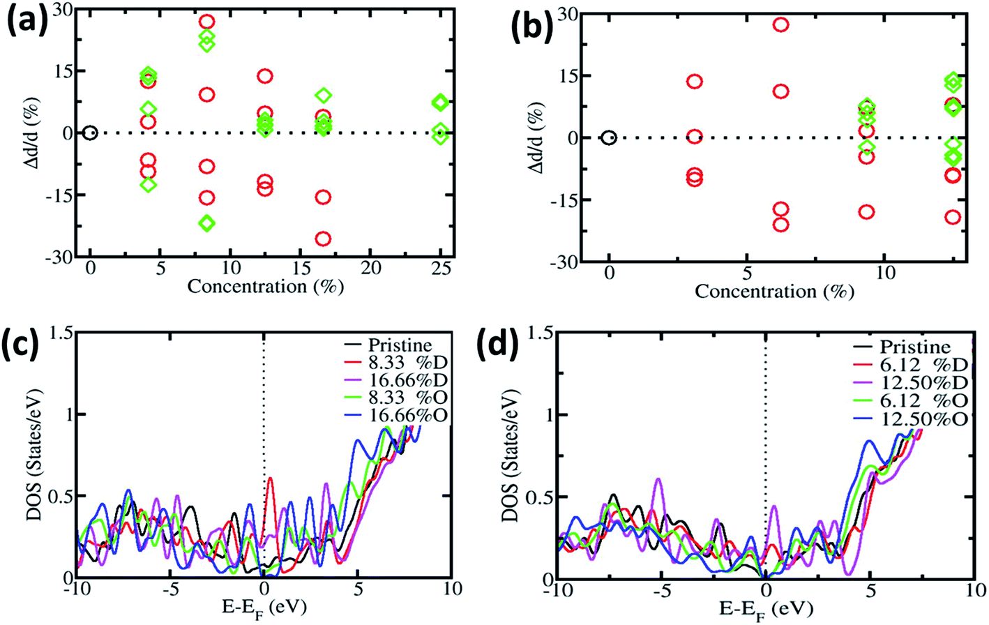 | ||
| Fig. 5 Relative change in diameter with defective and oxygen doped (a) SWNT(6,0) and (b) SWNT(8,0). Electronic density of states (DOS) of pristine, defective and oxygen doped CNTs (c) SWNT(6,0) and (d) SWNT(8,0). | ||
Furthermore we calculated the electronic density of states (DOS) of pristine, defective and oxygen doped SWNTs. Fig. 5c and d show the DOS of SWNT(6,0) and SWNT(8,0) respectively. Original SWNT(6,0) is metallic in nature and with the inclusion of defects, it remains metallic in nature (we have calculated up to 16.66% for SWNT(6,0)). On the other hand, with oxygen substitution it becomes semiconducting in nature. The original SWNT(8,0) is semiconducting in nature and stays semiconducting with oxygen doping. However it becomes metallic with the incorporation of defects. Other researchers have found similar effects like ours.72–74
4. Conclusions
In conclusion, we provide a mechanism for the oxidative plasma unzipping of MWCNTs. The high density plasma interaction of CNTs has made a lot of surface changes. The evolution of the surface morphology provides us with nanostructured petals in oxygen plasma environments. The oxygen ions in the plasma have created cracks and oxidized the tubes. This high density plasma is very efficient for unzipping the carbon tubes to nanoribbons. Our method of plasma modification has an advantage over the present state of art microelectronic device fabrication and can be possible in large area synthesis.Conflicts of interest
There are no conflicts to declare.Acknowledgements
All the authors thank the CeNSE, Indian Institute of Science, Bangalore, India for providing characterization facilities. BVMK thanks UGC for providing the fellowship grant (TF Code: KABA 095 TF 03) to pursue the research work. KPSSH acknowledges the Server Farm Supercomputing facility at Korea Institute of Science and Technology, Korea.References
- H. W. Kroto, J. R. Heath, S. C. O’Brien, R. F. Curl and R. E. Smalley, Nature, 1985, 318, 162 CrossRef CAS.
- Science of fullerenes and carbon nanotubes, ed. M. S. Dresselhaus, G. Dresselhaus and P. C. Eklund, Academic Press, 1996 Search PubMed.
- S. Iijima, Nature, 1991, 354, 56 CrossRef CAS.
- Physical Properties of Carbon nanotubes, ed. R. Saito, G. Dresselhaus and M. S. Dresselhaus, Imperial College Press, 1998 Search PubMed.
- K. S. Novoselov, D. Jiang, F. Schedin, T. J. Booth, V. V. Khotkevich, S. V. Morozov and A. K. Geim, Proc. Natl. Acad. Sci. U. S. A., 2005, 102, 10451 CrossRef CAS PubMed.
- A. K. Geim and K. S. Novoselov, Nature, 2007, 6, 183 CrossRef CAS PubMed.
- A. Bachtold, P. Hadley, P. Nakanishi and C. Dekker, Science, 2001, 294, 1317 CrossRef CAS PubMed.
- X. Wang, Y. Ouyang, X. Li, H. Wang, J. Guo and H. Dai, Phys. Rev. Lett., 2008, 100, 206803 CrossRef PubMed.
- X. Li, X. Wang, L. Zhang, S. Lee and H. Dai, Science, 2008, 319, 1229 CrossRef CAS PubMed.
- Y. Che, H. Chen, H. Gui, J. Liu, B. Liu and C. Zhou, Semicond. Sci. Technol., 2014, 29, 073001 CrossRef.
- L. Valentini, I. Armentano, J. M. Kenny, C. Cantalini, L. Lozzi and S. Santucci, Appl. Phys. Lett., 2003, 82, 961 CrossRef CAS.
- R. J. Chen, S. Bangsaruntip, K. A. Drouvalakis, N. W. S. Kam, M. Shim, Y. Li, W. Kim, P. J. Utz and H. Dai, Proc. Natl. Acad. Sci. U. S. A., 2003, 100, 4984 CrossRef CAS PubMed.
- C. R. Martin and P. Kohli, Nat. Rev. Drug Discovery, 2003, 2, 29 CrossRef CAS PubMed.
- F. L. Meng, Z. Guo and X. J. Huang, Trends Anal. Chem., 2015, 68, 37 CrossRef CAS.
- T. Wang, D. Huang, Z. Yang, S. Xu, G. He, X. Li, N. Hu, G. Yin, D. He and L. A. Zhang, Nano-Micro Lett., 2016, 8, 95 CrossRef.
- S. S. Varghese, S. Lonkar, K. K. Singh, S. Swaminathan and A. Abdala, Sens. Actuators, B, 2015, 218, 160 CrossRef CAS.
- W. Zhang, Z. Zhang and Y. Zhang, Nanoscale Res. Lett., 2011, 6, 555 CrossRef PubMed.
- J. Liu, L. Cui and D. Losic, Acta Biomater., 2013, 9, 9243 CrossRef CAS PubMed.
- B. J. Landi, M. J. Ganter, C. D. Cress, R. A. DiLeo and R. P. Raffaelle, Energy Environ. Sci., 2009, 2, 638 CAS.
- A. Hakimian, S. Kamarthi, S. Erbis, K. M. Abraham, T. P. Cullinane and J. A. Isaacs, Environ. Sci.: Nano, 2015, 2, 463 RSC.
- R. Raccichini, A. Varzi, S. Passerini and B. Scrosati, Nat. Mater., 2015, 14, 271 CrossRef CAS PubMed.
- M. F. El-Kady, Y. Shao and R. B. Kaner, Nat. Rev. Mater., 2016, 1, 16033 CrossRef CAS.
- Y. Sonvane, S. K. Gupta, P. I. Raval, I. Lukačević and P. B. Thakor, Chem. Phys. Lett., 2015, 634, 16 CrossRef CAS.
- A. Behnam, A. S. Lyons, M. H. Bae, E. K. Chow, S. Islam, C. M. Neumann and E. Pop, Nano Lett., 2012, 12, 4424 CrossRef CAS PubMed.
- R. H. Kim and M. H. Bae, et al., Nano Lett., 2011, 11, 3881 CrossRef CAS PubMed.
- S. Dutta and S. K. Pati, J. Mater. Chem., 2010, 20, 8207 RSC.
- P. Kumar, L. S. Panchakarla and C. N. R. Rao, Nanoscale, 2011, 3, 2127 RSC.
- I. Janowska, O. Ersen, T. Jacob, P. Vennégues, D. Bégin, M. J. Ledoux and C. Pham-Huu, Appl. Catal., A, 2009, 371, 22 CrossRef CAS.
- R. Pelalak, M. Baniadam and M. Maghrebi, Appl. Phys. A, 2013, 111, 951 CrossRef CAS.
- A. Fasoli, A. Colli, A. Lombardo and A. C. Ferrari, Phys. Status Solidi B, 2009, 246, 2514 CrossRef CAS.
- B. S. Archanjo, B. Fragneaud, L. G. Cancado, D. Winston, F. Miao, C. A. Achete and G. Medeiros-Ribeiro, Appl. Phys. Lett., 2014, 104, 193114 CrossRef.
- J. Bai, X. Duan and Y. Huang, Nano Lett., 2009, 9, 2083 CrossRef CAS PubMed.
- Y. Byu and A. Coskun, Chem. Mater., 2015, 27, 2576 CrossRef.
- J. Cai, P. Ruffieux and X. Feng, et al., Nature, 2010, 466, 470 CrossRef CAS PubMed.
- Z. S. Wu, W. Ren, L. Gao, B. Liu, J. Zhao and H. M. Cheng, Nano Res., 2010, 3, 16 CrossRef CAS.
- M. Wang, S. Zhang, Y. Song, J. Dong, H. Wei, H. Xie, X. Fang, L. Shao, Y. Huang and Z. Jiang, Nanotechnology, 2016, 27, 465702 CrossRef PubMed.
- W. Xu and T. W. Lee, Mater. Horiz., 2016, 3, 186 RSC.
- S. Cho, K. Kikuchi and A. Kawasaki, Carbon, 2011, 49, 3865 CrossRef CAS.
- A. L. Elias, A. R. Botello-Méndez, D. Meneses-Rodríguez and V. J. González, et al., Nano Lett., 2010, 10, 366 CrossRef CAS PubMed.
- D. V. Kosynkin, A. L. Higginbotham, A. Sinitskii, J. R. Lomeda, A. Dimiev, B. K. Price and J. M. Tour, Nature, 2009, 458, 872 CrossRef CAS PubMed.
- J. L. Li, K. N. Kudin, M. J. McAllister, R. K. Prud’homme, I. A. Aksay and R. Car, Phys. Rev. Lett., 2006, 96, 176101 CrossRef PubMed.
- P. M. Ajayan and B. I. Yakobson, Nature, 2006, 441, 818 CrossRef CAS PubMed.
- W. Xia, Y. Wang, R. Bergsträßer, S. Kundu and M. Muhler, Appl. Surf. Sci., 2007, 254, 247 CrossRef CAS.
- A. Felten, J. Ghijsen, J. J. Pireaux, R. L. Johnson, C. M. Whelan, D. Liang, G. V. Tendeloo and C. Bittencourt, J. Phys. D: Appl. Phys., 2007, 40, 7379 CrossRef CAS.
- C. Bittencourt, C. Navio, A. Nicolay, B. Ruelle, T. Godfroid, R. Snyders, J. F. Colomer, M. J. Lagos, X. Ke, G. V. Tendeloo, L. S. Martinez and C. P. Ewels, J. Phys. Chem. C, 2011, 115, 20412 CAS.
- P. Clément, A. Ramos, A. Lazaro, L. Molina-Luna, C. Bittencourt, D. Girbau and E. Llobet, Sens. Actuators, B, 2015, 208, 444 CrossRef.
- C. Chen, B. Liang, A. Ogino, X. Wang and M. Nagatsu, J. Phys. Chem. C, 2009, 113, 7659 CAS.
- F. Morales-Lara, M. J. Perez-Mendoza, D. Altmajer-Vaz, M. Garcia-Román, M. Melguizo, F. J. Lopez-Garzón and M. Domingo-García, J. Phys. Chem. C, 2013, 117, 11647 CAS.
- V. Chirila, G. Marginean and W. Brandl, Surf. Coat. Technol., 2005, 200, 548 CrossRef CAS.
- T. Xu, J. Yang, J. Liu and Q. Fu, Appl. Surf. Sci., 2007, 253, 8945 CrossRef CAS.
- B. Ruelle, A. Felten, J. Ghijsen and P. Dubois, et al., Micron, 2009, 40, 85 CrossRef CAS PubMed.
- G. Kalita, S. Adhikari, H. R. Aryal, R. Afre, T. Soga, M. Sharon and M. Umeno, Curr. Appl. Phys., 2009, 9, 346 CrossRef.
- S. Hussain, R. Amade, E. Jover and E. Bertran, J. Mater. Sci., 2013, 48, 7620 CrossRef CAS.
- L. Ma, J. Wang and F. Ding, Angew. Chem., Int. Ed., 2012, 51, 1161 CrossRef CAS PubMed.
- J. G. Jones, A. R. Waite, C. Muratore and A. A. Voevodin, J. Vac. Sci. Technol., B: Microelectron. Nanometer Struct.: Process., Meas., Phenom., 2008, 26, 995 CrossRef CAS.
- S. Mohammadi, Z. Kolahdouz and S. Mohajerzadeh, J. Mater. Chem. C, 2013, 1, 1309 RSC.
- A. Hassanien, M. Tokumoto, P. Umek, D. Vrbanič, M. Mozetič, D. Mihailović, P. Venturini and S. Pejovnik, Nanotechnology, 2005, 16, 278 CrossRef CAS PubMed.
- M. J. Behr, E. A. Gaulding, K. A. Mkhoyan and E. S. Aydil, J. Vac. Sci. Technol., B: Nanotechnol. Microelectron.: Mater., Process., Meas., Phenom., 2010, 28, 1187 CAS.
- S. Iijima, P. M. Ajayan and T. Ichihashi, Phys. Rev. Lett., 1992, 69, 3100 CrossRef CAS PubMed.
- C. J. Lee and J. Park, Appl. Phys. Lett., 2000, 77, 3397 CrossRef CAS.
- F. Ding, A. R. Harutyunyan and B. I. Yakobson, Proc. Natl. Acad. Sci. U. S. A., 2009, 106, 2506 CrossRef CAS PubMed.
- K. P. S. S. Hembram and G. M. Rao, Mater. Lett., 2012, 72, 68 CrossRef CAS.
- J. K. Lee, S. Lee and P. John, et al., Appl. Phys. Lett., 2013, 102, 16191 Search PubMed.
- S. H. Jhi, S. G. Louie and M. L. Cohen, Phys. Rev. Lett., 2005, 95, 226403 CrossRef PubMed.
- D. J. Mann and M. D. Halls, J. Chem. Phys., 2002, 116, 9014 CrossRef CAS.
- G. Zhang, W. Duan, G. Zhou and B. Gu, Solid State Commun., 2002, 122, 121 CrossRef CAS.
- K. P. S. S. Hembram and G. M. Rao, Appl. Surf. Sci., 2011, 257, 5503 CrossRef CAS.
- B. V. M. Kumar, R. Thomas, A. Mathew and G. M. Rao, et al., Adv. Mater. Lett., 2014, 5, 543 CrossRef CAS.
- K. D. Vargheese and G. M. Rao, Rev. Sci. Instrum., 2000, 71, 467 CrossRef CAS.
- P. Giannozzi, et al., J. Phys.: Condens. Matter, 2009, 21, 395502 CrossRef PubMed.
- J. P. Perdew, K. Burke and M. Ernzerhof, Phys. Rev. Lett., 1996, 77, 3865 CrossRef CAS PubMed.
- D. Vanderbilt, Phys. Rev. B: Condens. Matter Mater. Phys., 1990, 41, 7892 CrossRef.
- H. J. Monkhorst and J. D. Pack, Phys. Rev. B: Condens. Matter Mater. Phys., 1976, 13, 5188 CrossRef.
- M. Methfessel and A. T. Paxton, Phys. Rev. B: Condens. Matter Mater. Phys., 1989, 40, 3616 CrossRef CAS.
Footnote |
| † Electronic supplementary information (ESI) available. See DOI: 10.1039/c7ra04318j |
| This journal is © The Royal Society of Chemistry 2017 |