 Open Access Article
Creative Commons Attribution 3.0 Unported Licence
Stable CO anti-poisoning and high durability of a Pt electrocatalyst supported on carbon nanotubes†
Jiuxiao Sun‡
a,
Xinxin Yu‡b,
Quan Zhangb,
Ying Lingb and
Zehui Yang *b
*b
aCollege of Materials Science and Engineering, Wuhan Textile University, Fangzhi RD, Wuhan, 430200, China
bSustainable Energy Laboratory, Faculty of Materials Science and Chemistry, China University of Geosciences Wuhan, 388 Lumo RD, Wuhan, 430074, China. E-mail: yeungzehui@mail.com
First published on 15th August 2017
Abstract
Stable CO anti-poisoning and high durability of an anodic electrocatalyst are very important for direct methanol fuel cells (DMFCs). Here, we report a Pt electrocatalyst with stable CO tolerance and high durability, in which Pt nanoparticles were homogeneously deposited on poly(vinylpyrrolidone) wrapped carbon nanotubes and the Pt nanoparticles were further coated with poly(2,5-benzimidazole) (ABPBI) via in situ polymerization. Although the electrochemical surface area (ECSA) and methanol oxidation reaction (MOR) activity decreased by ∼13% after coating the ABPBI layer on the Pt nanoparticles, the durability was dramatically enhanced due to the presence of ABPBI, which decelerates the Pt migration and aggregation. Meanwhile, the introduction of ABPBI to the electrocatalyst results in high and stable CO tolerance. After a durability test, the CO oxidation peak of the ABPBI coated electrocatalyst was almost stable (only 12 mV shift) compared to those of commercial (96 mV) and non-coated (108 mV) electrocatalysts. Thus, ABPBI is of importance to improve the durability and maintain stable CO tolerance of an electrocatalyst.
Introduction
With the rapid development of the global economy and consumption of fossil fuels, there is an ever-increasing demand for sustainable and renewable power sources, which has inspired tremendous research on clean energy conversion and storage devices to meet the future energy requirements.1–3 Direct methanol fuel cells (DMFCs) have attracted considerable attention due to their sustainability and environmentally friendly nature, and they can be alternative power sources for portable devices.4–6 Due to the usage of methanol instead of hydrogen as fuel, high energy density, and easy storage and transportation are expected for DMFCs. Besides these advantages, DMFCs still suffer from three main problems: (i) carbon monoxide (CO) poisoning of the platinum (Pt) electrocatalyst; (ii) low durability; and (iii) sluggish methanol oxidation reaction (MOR). CO poisoning and low durability are induced by incomplete methanol oxidation and weak interaction between Pt and carbon supports, respectively.7–9 Thus, development of DMFC anodic electrocatalysts with high durability and CO tolerance is essential for the wide commercialization of DMFCs.As well known, Pt shows the highest methanol oxidation capability and Pt is requirable for fabrication of anodic electrocatalyst of DMFCs;10–13 while, Pt electrocatalyst faces serious CO poisoning problem.14–16 Alloying Pt with ruthenium (Ru) has been proved to be an efficient way to enhance the CO tolerance of electrocatalyst due to the lower potential for the formation of Ru(OH)ads species compared to that of Pt(OH)ads species.17,18 However, Ru is unstable in acidic environment and CO tolerance of electrocatalyst declines during the long-term operation.19 Intensive studies have focused on the stabilization of Ru; while, Ru dissolution was only decelerated and CO tolerance of electrocatalyst degraded resulting in deterioration in fuel cell performance.20,21 Thus, stable CO tolerance is highly desirable for long-term operation of DMFCs. Coating Pt nanoparticles with poly(vinylphosphonic acid) (PVPA),22–25 polybenzimidazole (PBI),26 polyaniline (PANI)27 and poly(vinyl pyrrolidone) (PVP)28 is proved to enhance the CO tolerance of electrocatalyst; while, CO tolerance still deteriorated during the long-term operation due to the growth of Pt nanoparticles, which was highly important for CO tolerance.
Based on the above consideration, in this work, we deposited Pt nanoparticles on carbon nanotubes (CNTs) after wrapping with PVP and further coated with poly(2,5-benzimidazole) (ABPBI) via in situ polymerization as schematically illustrated in Fig. 1. Due to the amphiphilic nature, poly(vinylpyrrolidone) (PVP), a commercially available inexpensive polymer, is known to disperse carbon nanotubes in water. As reported previously, PVP is essential to enhance the CO tolerance of Pt electrocatalyst28 and ABPBI layer on Pt nanoparticles was expected to stabilize the Pt nanoparticles and to prevent Pt aggregation resulting in stable CO tolerance of electrocatalyst since Pt nanoparticles size highly affects the CO tolerance of electrocatalyst.
Experimental
Materials
Methanol, 3,4-diaminobenzoic acid (DABA), sulphuric acid, and poly(phosphoric acid) (PPA), isopropanol, H2SO4, N,N-dimethylformamide (DMF), hydrogen hexachloroplatinate hexahydrate (H2PtCl6·6H2O), poly(vinylpyrrolidone) (PVP, K30) and ethylene glycol (EG) were purchased from Sinopharm Chemical Reagent Co., Ltd. Commercial CB/Pt (Pt: 40 wt%) and were purchased from Alfa Aesar. Nafion solution (5 wt%) were purchased from Sigma-Aldrich. Aqueous solutions were prepared using Milli-Q water and all chemicals were used as received without further purification.Synthesis of CNT/PVP/Pt/ABPBI
CNT/PVP/Pt was synthesized according to our previous reports.29 Briefly, 10 mg of CNTs was wrapped by PVP (30 mg) using sonication for 2 h in water. The resultant composite was collected by filtration, washing and drying under vacuum at 80 °C. The Pt loading was carried out by reduction of H2PtCl6·6H2O at 140 °C for 6 h under nitrogen atmosphere. The resultant solution was filtered, washed, and dried overnight under vacuum at 80 °C. 20 mg of CNT/PVP/Pt was dispersed in 20 mL of water by sonication for 10 min to which 20 mg of the PVP was added, then ultra-sonicated for 1 h followed by filtration using a 0.2 μm PTFE filter paper to collect the product, which was washed several times with Milli-Q water to remove free PVP, then dried overnight at 80 °C under vacuum to remove any residual solvent to obtain CNT/PVP/Pt. 100 mg of CNT/PVP/Pt and 10 mg of DABA were mixed in 100 g of PPA by stirring, and then increase the temperature to 200 °C under stable N2 follow and the polymerization was terminated after 5 h. The resultant solution was condensed in Milli-Q water and NaOH was added to neutralize the solution to remove PPA. The composite was collected by filtration, washing with DMAc to remove monomer and dried at 80 °C under vacuum.Material characterization
X-ray photoelectron spectroscopy (XPS) was carried out using a ThermoScientific K-Alpha instrument. The pressure in the XPS analysis chamber was kept below 10−9 Pa during the measurements. During the calibration process, the binding energy (BE) of C1s peak was fixed at 284.5 eV as standard. Thermo-gravimetric analysis (TGA) was conducted using a TGA analyzer (NETZSCH5) at the heating rate of 10 °C min−1 and 100 mL min−1 oxygen-flow. The TEM micrographs were measured using JEM-2010 (JEOL, acceleration voltage of 120 kV) electron microscope.Electrochemical measurements
The electrochemical measurements were performed using a glassy carbon electrode (GCE) with a conventional three-electrode system in a vessel at 25 °C. GCE with a geometric surface area of 0.126 cm2 was used as the working electrode. Pt wire and Ag/AgCl were used as the counter and reference electrodes, respectively. The potential of the electrode was controlled by CHi604e potentiostat. The electrocatalyst ink was prepared as follows. The electrocatalyst (1.0 mg) was ultrasonically dispersed in 80% isopropanol aq. (v/v = 4![[thin space (1/6-em)]](https://www.rsc.org/images/entities/char_2009.gif) :
:![[thin space (1/6-em)]](https://www.rsc.org/images/entities/char_2009.gif) 1, 2.0 mL) to form homogeneous suspension, which was casted on GCE and the loading amount of Pt was controlled at 20 μg cm−2, then air-dried. Cyclic voltammetry (CV) measurement was carried at the scan rate of 50 mV s−1 in N2-saturated 0.5 M H2SO4 electrolyte after activation of the electrocatalyst and electrochemical surface area (ECSA) value was determined from CV curves. All the potentials were referenced to the reference hydrogen electrode (RHE).
1, 2.0 mL) to form homogeneous suspension, which was casted on GCE and the loading amount of Pt was controlled at 20 μg cm−2, then air-dried. Cyclic voltammetry (CV) measurement was carried at the scan rate of 50 mV s−1 in N2-saturated 0.5 M H2SO4 electrolyte after activation of the electrocatalyst and electrochemical surface area (ECSA) value was determined from CV curves. All the potentials were referenced to the reference hydrogen electrode (RHE).
Methanol oxidation reaction (MOR)
The MOR was evaluated in N2-saturated 0.5 M H2SO4 and 1 M methanol at 25 °C with the scan rate of 50 mV s−1.Pt stability test
The Pt stability was tested using the protocol of the Fuel Cell Commercialization Conference of Japan (FCCJ) (measured in N2-saturated 0.5 M H2SO4 at 25 °C), in which the potential was kept at 0.6 V vs. RHE for 3 s, then applied up to 1 V vs. RHE for another 3 s. The procedure was cycled, and the CV measurement was carried out after every 600 cycles (see ESI, Fig. S1†).Results and discussion
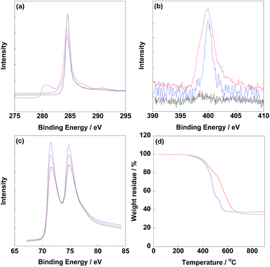
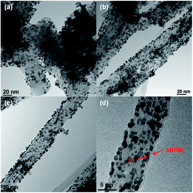
Before electrochemical analysis, some fundamental characterizations were carried out. As shown in Fig. 2a, C1s peaks were calibrated at 284.5 eV as standard for all electrocatalysts. N1s peaks were clearly observed at 400 eV for CNT/PVP/Pt and CNT/PVP/Pt/ABPBI.29,30 Meanwhile, higher intensity of N1s peak was found for CNT/PVP/Pt/ABPBI with relative to that of CNT/PVP/Pt (Fig. 2b), which was due to the additional nitrogen atoms for ABPBI. Not surprisingly, Pt4f peaks were found at 71.4 eV and 75.0 eV (Fig. 2c) ascribing to Pt4f7/2 and Pt4f5/2, respectively.31,32 From Fig. 2d, the Pt amounts in CNT/PVP/Pt and CNT/PVP/Pt/ABPBI were 38.0 wt% and 34.8 wt%, respectively, which were consistent with ICP-MS measurements (Elan DRC-e, PerkinElmer Inc). A decrease in Pt amount was found after coating with ABPBI and ABPBI amount in CNT/PVP/Pt/ABPBI was calculated to be 8.4 wt% based on the constant weight ratio between CNT/PVP and Pt before and after ABPBI coating. As shown in Fig. S2,† a board peak in the band of 3500 cm−1 to 3000 cm−1 was observed in CNT/PVP/Pt/ABPBI, which was assigned to the –NH stretching peak from ABPBI. The TGA and FT-IR results were indicative of the presence of ABPBI in the newly synthesized electrocatalyst. Pt nanoparticles were homogeneously deposited on CNT/PVP as shown in Fig. 3b and c and commercial CB/Pt was used as control sample (Fig. 3a). The Pt sizes of CNT/PVP/Pt and CNT/PVP/Pt/ABPBI were calculated to be 3.0 ± 0.1 nm and 3.4 ± 0.2 nm (Fig. S3†) from TEM images. Also, the ABPBI layer was clearly observed on Pt nanoparticles as shown in Fig. 3d and the thickness was 1 nm.It is of importance to determine the electrochemical surface area (ECSA) of newly synthesized electrocatalysts, which is calculated based on the following equation:
| ECSA = QH/(210 × Pt loading amount on electrode) | (1) |
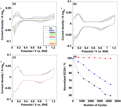
ECSAs of commercial CB/Pt, CNT/PVP/Pt and CNT/PVP/Pt/ABPBI were 71.1 m2 gPt−1, 92.9 m2 gPt−1 and 80.8 m2 gPt−1 as shown in Fig. 4, respectively. Compared to CNT/PVP/Pt/ABPBI, CNT/PVP/Pt/ABPBI showed a decrease (13%) in ECSA due to the ABPBI layer covered on Pt nanoparticles; while, ECSA of CNT/PVP/Pt/ABPBI was still higher compared to commercial CB/Pt. It is essential to calculate the Pt utilization efficiency to estimate electrocatalysts with different Pt size as below:
| Pt utilization efficiency (%) = (ECSA/TSA) × 100% | (2) |
| TSA = 6/ρd | (3) |
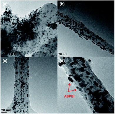
Thus, Pt utilization efficiency of CNT/PVP/Pt and CNT/PVP/Pt/ABPBI reached 100% and 98%, which were higher compared to commercial CB/Pt (84%) due to the different carbon supporting materials. As well known, CB has some micropores on surfaces and Pt nanoparticles would be embedded into these micropores during Pt deposition;36,37 however, in case of CNT/PVP/Pt and CNT/PVP/Pt/ABPBI, all Pt nanoparticles were deposited on surfaces of CNT/PVP. Durability of electrocatalyst is evaluated by potential cycles from 0.6 V to 1.0 V vs. RHE, in which Pt nanoparticles were oxidized/reduced resulting in Pt aggregation. As shown in Fig. 4a, hydrogen adsorption/desorption peaks were gradually decreased with increase in potential cycles resulting in 50% loss in ECSA, which was due to the Pt growth because of weak interaction between Pt nanoparticles and carbon supports. ECSA of CNT/PVP/Pt also faced a gradual decrease in ECSA and was lost 35% after 4200 potential cycles. Interestingly, hydrogen adsorption/desorption peaks were stable during potential cycling for CNT/PVP/Pt/ABPBI. The stable ECSA of CNT/PVP/Pt/ABPBI would be due to the ABPBI coating on Pt nanoparticles suppressing the Pt aggregation. After durability test, the electrocatalysts were measured by TEM as shown in Fig. 5. As can be seen, Pt nanoparticles of commercial CB/Pt and CNT/PVP/Pt were grown to 5.4 ± 0.5 nm and 4.4 ± 0.4 nm, respectively; while, CNT/PVP/Pt/ABPBI showed stable Pt size (3.5 ± 0.2 nm after durability test, Fig. S4†). Thus, the ABPBI layer on Pt nanoparticles was important to improve the durability of electrocatalyst. After durability test, the Pt utilization efficiencies of commercial CB/Pt and CNT/PVP/Pt decreased from 84% and 100–69% and 95%, respectively. CNT/PVP/Pt/ABPBI showed a stable Pt utilization efficiency during the durability test. Meanwhile, the ABPBI layer was still observed after durability as shown in Fig. 5d test suggesting that ABPBI layer was stable during the potential cycling.
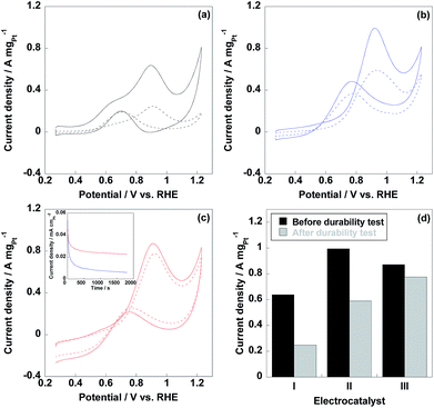
Methanol oxidation reaction (MOR) is the anodic reaction in DMFCs, thus, evaluation of MOR is prominently essential for DMFC anodic electrocatalyst. As shown in Fig. 6, two peaks were observed in MOR test representing anodic (If) and reverse anodic peaks (Ib), respectively. During the If peak, methanol is oxidized to CO2, CO and HCOOH et al. and the Ib peak represents the further oxidation of CO and HCOOH to CO2, thus, If/Ib ratio is indicative of CO tolerance for electrocatalyst.38–40 It should be noted that If/Ib ratio is a rough way to estimate the CO tolerance of electrocatalyst and the accurate CO tolerance needs to be confirmed by CO stripping voltammetry experiment. As displayed in Table 1, CNT/PVP/Pt/ABPBI showed higher If/Ib ratio compared to CNT/PVP/Pt, which would be due to the formation of Pt–OH![[double bond, length as m-dash]](https://www.rsc.org/images/entities/char_e001.gif) N and Pt–OH is highly important for enhancement in CO tolerance26 since Pt–OH can react with Pt–OH to recover the CO poisoned Pt nanoparticles (Pt–OH + Pt–CO → Pt + CO2 + H+). After coating with ABPBI, CNT/PVP/Pt/ABPBI showed twice higher CO tolerance by comparison with CNT/PVP/Pt. Meanwhile, If/Ib ratio of commercial CB/Pt was sharply decreased due the Pt aggregation because Pt size affects the CO tolerance of electrocatalyst. Current density of If peak was used for evaluation of electrocatalytic activity of electrocatalyst and current density of CNT/PVP/Pt/ABPBI reached 0.87 A mgPt−1 before durability test, which was decreased by 13% compared to CNT/PVP/Pt (1.0 A mgPt−1) due to the presence of ABPBI layer on Pt nanoparticles. However, CNT/PVP/Pt/ABPBI showed 1.4 times higher MOR activity with relative to commercial CB/Pt (0.64 A mgPt−1). MOR activity of commercial CB/Pt and CNT/PVP/Pt by 60% and 41% after 4200 potential cycles as displayed in Fig. 6d; while, CNT/PVP/Pt/ABPBI showed almost stable MOR activity during durability test, which showed only 11% loss in current density of If peak due to the highest stability (Fig. 4d). As displayed in Table 2, the electro-activity of CNT/PVP/Pt/ABPBI (0.87 A mgPt−1) was one of the highest values among recently published literatures. Chronopotentiometry is a useful way to estimate the electro-activity of electrocatalyst. As shown in Fig. 6, the current density of CNT/PVP/Pt sharply decreased due to the poisoning of Pt electrocatalyst; while, due to the higher CO anti-poisoning, CNT/PVP/Pt/ABPBI possessed more stable activity compared to CNT/PVP/Pt.
N and Pt–OH is highly important for enhancement in CO tolerance26 since Pt–OH can react with Pt–OH to recover the CO poisoned Pt nanoparticles (Pt–OH + Pt–CO → Pt + CO2 + H+). After coating with ABPBI, CNT/PVP/Pt/ABPBI showed twice higher CO tolerance by comparison with CNT/PVP/Pt. Meanwhile, If/Ib ratio of commercial CB/Pt was sharply decreased due the Pt aggregation because Pt size affects the CO tolerance of electrocatalyst. Current density of If peak was used for evaluation of electrocatalytic activity of electrocatalyst and current density of CNT/PVP/Pt/ABPBI reached 0.87 A mgPt−1 before durability test, which was decreased by 13% compared to CNT/PVP/Pt (1.0 A mgPt−1) due to the presence of ABPBI layer on Pt nanoparticles. However, CNT/PVP/Pt/ABPBI showed 1.4 times higher MOR activity with relative to commercial CB/Pt (0.64 A mgPt−1). MOR activity of commercial CB/Pt and CNT/PVP/Pt by 60% and 41% after 4200 potential cycles as displayed in Fig. 6d; while, CNT/PVP/Pt/ABPBI showed almost stable MOR activity during durability test, which showed only 11% loss in current density of If peak due to the highest stability (Fig. 4d). As displayed in Table 2, the electro-activity of CNT/PVP/Pt/ABPBI (0.87 A mgPt−1) was one of the highest values among recently published literatures. Chronopotentiometry is a useful way to estimate the electro-activity of electrocatalyst. As shown in Fig. 6, the current density of CNT/PVP/Pt sharply decreased due to the poisoning of Pt electrocatalyst; while, due to the higher CO anti-poisoning, CNT/PVP/Pt/ABPBI possessed more stable activity compared to CNT/PVP/Pt.
| Electrocatalyst | If/Ib (before durability) | If/Ib (after durability) |
|---|---|---|
| CB/Pt | 3.4 | 1.3 |
| CNT/PVP/Pt | 2.0 | 1.6 |
| CNT/PVP/Pt/ABPBI | 4.0 | 3.3 |
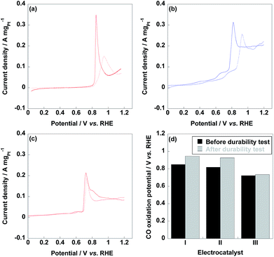
As shown in Fig. 7, CO stripping voltammetry curves were recorded before and after durability test to confirm the CO tolerance of electrocatalyst since CO stripping voltammetry was an accurate experiment to evaluate the CO tolerance of electrocatalyst. Compared to commercial CB/Pt (850 mV) and CNT/PVP/Pt (818 mV), CO oxidation peak of CNT/PVP/Pt/ABPBI (722 mV) was negatively shifted suggesting that the adsorbed CO species could be easily oxidized by Pt nanoparticles. The higher CO tolerance of CNT/PVP/Pt/ABPBI would be due to the introducing of ABPBI layer on Pt nanoparticles, which could form Pt–N bonding and weak the binding energy between Pt and CO species. After durability test, CO oxidation peak of CNT/PVP/Pt/ABPBI (12 mV positive shift) was almost stable compared to those of commercial CB/Pt (96 mV positive shift) and CNT/PVP/Pt (108 mV positive shift, Fig. 7d) indicating a stable CO tolerance during the long-term operation. The stable CO tolerance during long-term operation is highly desirable for DMFC operation.
Conclusions
In summary, we have successfully fabricated a Pt electrocatalyst supported on CNT and further coated with ABPBI layer (1 nm) via in situ polymerization. Due to the ABPBI layer on Pt nanoparticles, 13% of electrochemical surface area (ECSA) as well as methanol oxidation activity were lost; while, ABPBI coated electrocatalyst showed higher durability (stable ECSA and MOR activity) compared to non-coated and commercial electrocatalysts (50% loss) due to the protection of ABPBI layer. Meanwhile, ABPBI coated electrocatalyst showed a more stable CO tolerance during the durability test because of the higher stabilization of Pt nanoparticles. Thus, the newly fabricated electrocatalyst is utilizable for real DMFC long-term operation without any deterioration in fuel cell performance.Conflicts of interest
There are no conflicts to declare.Acknowledgements
The Project was supported by the Fundamental Research Funds for the Central Universities, China University of Geosciences (Wuhan) (CUG170615).Notes and references
- M.-M. Titirici, R. J. White, N. Brun, V. L. Budarin, D. S. Su, F. del Monte, J. H. Clark and M. J. MacLachlan, Chem. Soc. Rev., 2015, 44, 250–290 RSC.
- M. Winter and R. J. Brodd, Chem. Rev., 2004, 104, 4245–4270 CrossRef CAS PubMed.
- M. P. Rodgers, L. J. Bonville, H. R. Kunz, D. K. Slattery and J. M. Fenton, Chem. Rev., 2012, 112, 6075–6103 CrossRef CAS PubMed.
- M. A. Scibioh, I.-H. Oh, T.-H. Lim, S.-A. Hong and H. Y. Ha, Appl. Catal., B, 2008, 77, 373–385 CrossRef CAS.
- H. Yang, J. Zhang, K. Sun, S. Zou and J. Fang, Angew. Chem., Int. Ed., 2010, 49, 6848–6851 CrossRef CAS PubMed.
- J. Chang, L. Feng, C. Liu, W. Xing and X. Hu, Energy Environ. Sci., 2014, 7, 1628–1632 CAS.
- T. Iwasita, Electrochim. Acta, 2002, 47, 3663–3674 CrossRef CAS.
- X. Zhao, M. Yin, L. Ma, L. Liang, C. Liu, J. Liao, T. Lu and W. Xing, Energy Environ. Sci., 2011, 4, 2736–2753 CAS.
- X. Li and A. Faghri, J. Power Sources, 2013, 226, 223–240 CrossRef CAS.
- H. Liu, C. Song, L. Zhang, J. Zhang, H. Wang and D. P. Wilkinson, J. Power Sources, 2006, 155, 95–110 CrossRef CAS.
- Z. Zhou, S. Wang, W. Zhou, G. Wang, L. Jiang, W. Li, S. Song, J. Liu, G. Sun and Q. Xin, Chem. Commun., 2003, 9, 394–395 RSC.
- L. Wei, Y.-J. Fan, J.-H. Ma, L.-H. Tao, R.-X. Wang, J.-P. Zhong and H. Wang, J. Power Sources, 2013, 238, 157–164 CrossRef CAS.
- R.-X. Wang, Y.-J. Fan, L. Wang, L.-N. Wu, S.-N. Sun and S.-G. Sun, J. Power Sources, 2015, 287, 341–348 CrossRef CAS.
- N. R. Elezovic, V. R. Radmilovic and N. V. Krstajic, RSC Adv., 2016, 6, 6788–6801 RSC.
- H. Zhang and C. Cheng, J. Mater. Chem. A, 2016, 4, 15961–15967 CAS.
- Q. Wang, H. Tao, Z. Li, C. Chen, S. Liu, L. Han and X. Lu, J. Energy Chem., 2016, 25, 811–816 CrossRef.
- Z. Yang, X. Yu and F. Luo, RSC Adv., 2016, 6, 96416–96420 RSC.
- Z. Yang, X. Yu and Q. Zhang, RSC Adv., 2016, 6, 114014–114018 RSC.
- S. Wang, T. Cochell and A. Manthiram, Phys. Chem. Chem. Phys., 2012, 14, 13910–13913 RSC.
- Z. X. Liang, T. S. Zhao and J. B. Xu, J. Power Sources, 2008, 185, 166–170 CrossRef CAS.
- D. M. Han, Z. P. Guo, Z. W. Zhao, R. Zeng, Y. Z. Meng, D. Shu and H. K. Liu, J. Power Sources, 2008, 184, 361–369 CrossRef CAS.
- Z. Yang, M. R. Berber and N. Nakashima, J. Mater. Chem. A, 2014, 2, 18875–18880 CAS.
- Z. Yang, C. Kim, S. Hirata, T. Fujigaya and N. Nakashima, ACS Appl. Mater. Interfaces, 2015, 7, 15885–15891 CAS.
- Z. Yang, I. Moriguchi and N. Nakashima, ACS Appl. Mater. Interfaces, 2016, 8, 9030–9036 CAS.
- Z. Yang, I. H. Hafez, M. R. Berber and N. Nakashima, ChemCatChem, 2015, 7, 808–813 CrossRef CAS.
- T. Fujigaya, M. Okamoto, K. Matsumoto, K. Kaneko and N. Nakashima, ChemCatChem, 2013, 5, 1701–1704 CrossRef CAS.
- H. Gharibi, M. Amani, H. Pahlavanzadeh and M. Kazemeini, Electrochim. Acta, 2013, 97, 216–225 CrossRef CAS.
- Z. Yang and N. Nakashima, ChemCatChem, 2016, 8, 600–606 CrossRef CAS.
- Z. Yang and N. Nakashima, J. Mater. Chem. A, 2015, 3, 23316–23322 CAS.
- J. Sun, Y. Ling, Q. Zhang, X. Yu and Z. Yang, RSC Adv., 2017, 7, 29839–29843 RSC.
- W. Li, C. Liang, W. Zhou, J. Qiu, H. Li, G. Sun and Q. Xin, Carbon, 2004, 42, 436–439 CrossRef CAS.
- B. Fang, N. K. Chaudhari, M. S. Kim, H. K. Jung and J. S. Yu, J. Am. Chem. Soc., 2009, 131, 15330–15338 CrossRef CAS PubMed.
- D. Wang, H. L. Xin, Y. Yu, H. Wang, E. Rus, D. A. Muller and H. D. Abruña, J. Am. Chem. Soc., 2010, 132, 17664–17666 CrossRef CAS PubMed.
- D. Wang, H. L. Xin, R. Hovden, H. Wang, Y. Yu, D. A. Muller, F. J. Disalvo and H. D. Abruña, Nat. Mater., 2013, 12, 81–87 CrossRef CAS PubMed.
- Z. Yang, X. Yu, Y. Zhang and G. Xu, RSC Adv., 2016, 6, 108158–108163 RSC.
- Y.-C. Park, K. Kakinuma, H. Uchida, M. Watanabe and M. Uchida, J. Power Sources, 2015, 275, 384–391 CrossRef CAS.
- Y.-C. Park, H. Tokiwa, K. Kakinuma, M. Watanabe and M. Uchida, J. Power Sources, 2016, 315, 179–191 CrossRef CAS.
- L. H. Yu, C. H. Kuo and C. T. Yeh, J. Am. Chem. Soc., 2007, 129, 9999–10010 CrossRef PubMed.
- L. X. Ding, A. L. Wang, G. R. Li, Z. Q. Liu, W. X. Zhao, C. Y. Su and Y. X. Tong, J. Am. Chem. Soc., 2012, 134, 5730–5733 CrossRef CAS PubMed.
- J. P. Bosco, K. Sasaki, M. Sadakane, W. Ueda and J. G. Chen, Chem. Mater., 2010, 22, 966–973 CrossRef CAS.
- X. Sun, D. Li, Y. Ding, W. Zhu, S. Guo, Z. L. Wang and S. Sun, J. Am. Chem. Soc., 2014, 136, 5745–5749 CrossRef CAS PubMed.
- B. Singh and E. Dempsey, RSC Adv., 2013, 3, 2279–2287 RSC.
- H. Huang, Y. Fan and X. Wang, Electrochim. Acta, 2012, 80, 118–125 CrossRef CAS.
- Y. Fan, Z. Yang, P. Huang, X. Zhang and Y.-M. Liu, Electrochim. Acta, 2013, 105, 157–161 CrossRef CAS.
Footnotes |
| † Electronic supplementary information (ESI) available. See DOI: 10.1039/c7ra07331c |
| ‡ These authors equally contributed to this work. |
| This journal is © The Royal Society of Chemistry 2017 |


