
 Open Access Article
 This Open Access Article is licensed under a Creative Commons Attribution-Non Commercial 3.0 Unported Licence
CuO/Cu2O nanowire arrays grafted by reduced graphene oxide: synthesis, characterization, and application in photocatalytic reduction of CO2
Qianyu Zhang a,
Lihua Huangb,
Shifei Kangb,
Chaochuang Yinb,
Zhen Mac,
Lifeng Cui*a and
Yangang Wang*a
a,
Lihua Huangb,
Shifei Kangb,
Chaochuang Yinb,
Zhen Mac,
Lifeng Cui*a and
Yangang Wang*a
aSchool of Environment and Civil Engineering, Dongguan University of Technology, Guangdong 523808, China. E-mail: lifeng.cui@gmail.com; ygwang8136@gmail.com
bDepartment of Environmental Science and Engineering, University of Shanghai for Science and Technology, Shanghai 200093, China
cDepartment of Environmental Science and Engineering, Fudan University, Shanghai 200433, China
First published on 11th September 2017
Abstract
CuO/Cu2O nanowire arrays (NWAs) were prepared on a Cu foil substrate through a simple thermal process. The NWAs were then grafted with reduced graphene oxide (rGO) nanosheets via self-assembly. The combination of various characterization techniques including SEM, TEM, XRD, and XPS revealed the unique integration between CuO/Cu2O NWAs and umbrella-like rGO nanosheets. The CuO/Cu2O NWAs@rGO sample was found to be more active than bare CuO/Cu2O NWAs for the photocatalytic reduction of CO2 under simulated solar light. The improved photocatalytic activity was attributed to the slow recombination of charge carriers and the efficient transfer of photo-generated electrons through rGO nanosheets.
1. Introduction
With the rapid industrialization in the past century, the concentration of CO2 in the atmosphere is increasing tremendously due to fossil fuel combustion, thus leading to global climate changes and a serious threat to the environment.1,2 Photocatalytic conversion of CO2 into useful chemicals or fuels by semiconductors has been actively studied.3,4 Efficient photocatalysts for the reduction of CO2 are needed for this purpose.5–8 TiO2-based photocatalysts have attracted much attention because of their high stability, low cost, strong oxidation activity and outstanding electronic properties.9–11 However, the fast photoinduced electron–hole pair recombination and wide band gap (3.2 eV) are limitations for its large-scale application.12,13 Thus, it is important to develop visible-light-driven semiconductors for artificial photosynthesis for CO2 reduction.CuO and Cu2O, with narrow band gaps of 1.2 eV and 2 eV, respectively, are attractive p-type semiconductors for visible-light-driven photocatalysis. CuO and Cu2O have been widely investigated in gas sensors,14 solar cells,15 water splitting,16 electronic materials,17 and photocatalysts.5,7,18 Thus, the CuO/Cu2O system may be a good candidate for the photocatalytic reduction of CO2.
Nevertheless, the low electric conductivity of copper oxides may lead to rapid recombination of photo-generated electrons and holes limits their photocatalytic performance.7 The modification of copper oxides with some highly conductive carbon materials could improve their performance.19,20 Reduced graphene oxide (rGO) is a promising additive for hybrid materials, because of its unique properties such as superior mobility of charge carriers, extremely high specific surface area, and excellent conductivity.21,22 Thus, rGO may be added to the CuO/Cu2O system to improve the photocatalytic performance for CO2 reduction.
Although studies on the photocatalytic performance of CuO–rGO or Cu2O–rGO have been reported frequently, there are less research on CuO/Cu2O–rGO system. We anticipate that an ideal approach to construct copper oxide based high-performance photocatalyst is to synthesize a CuO/Cu2O–rGO nanostructure in which the CuO/Cu2O is tightly covered with ultrathin graphene nanosheets.
In this study, we successfully prepared CuO/Cu2O NWAs@rGO composites through a simple thermal process and a self-assembly procedure. The CuO/Cu2O NWAs@rGO composite showed enhanced photocatalytic activity for converting CO2 to CO under simulated solar light, owing to the presence of ultrathin rGO nanosheets that possesses high conductivity and results in slow recombination of charge carriers and efficient transfer of photo-generated electrons. Chemical and structural features of nanocomposites were characterized by XRD, XPS, Raman, SEM and TEM.
2. Experimental
2.1. Materials
Hydrochloric acid (36.0–38.0%), ethanol (99.7%) and methanol (99.5%) were purchased from Shanghai Chemical Corp. All chemicals involved here were of analytical grade and used without further purification. Copper foil (99.9%, 1 mm thickness) were purchased from Shengjili Metals Sales Company. Partially reduced graphene oxide (rGO) was purchased from Hengqiu Technique Company.2.2. Synthesis of CuO/Cu2O NWAs
CuO/Cu2O NWAs were fabricated by a simple thermal oxidation method. Copper foil (2 × 2 cm2) was carefully cleaned with a 6.0 M HCl solution in an ultrasound bath for 30 min to remove the CuO layer from the surface, then rinsed with deionized water and absolute ethanol for several times, and finally dried in air naturally. The bare Cu foil was calcinated at 600 °C in air for 4 h with a speed of 10 °C min−1 to obtain CuO/Cu2O NWAs.2.3. Synthesis of CuO/Cu2O NWAs@rGO
CuO/Cu2O NWAs@rGO was fabricated via a two-step self-assembly procedure. In that procedure, 30 mg reduced graphene oxide (rGO) was added into 300 mL of methanol, and after being ultrasonically treated for 3 h, rGO was exfoliated into thin sheets and disintegrated into a homogeneous suspension. CuO/Cu2O NWAs grown on the Cu foil were then put on a platform which was hung in the suspension and the suspension was stirred at room temperature for 24 h. Finally, the obtained sample was collected and dried in a vacuum oven at 60 °C.2.4. Chemical and structural characterizations of materials
X-ray diffraction (XRD) experiments were conducted on a Bruker D8 Advance X-ray diffractometer (Bruker Optics, Ettlingen, Germany) with Cu-Kα radiation, operated at 40 kV and 40 mA (scanning step: 0.02° s−1) in 2θ = 10–80°. Scanning electron microscopy (TEM) and transmission electron microscopy (TEM) experiments were conducted on a Tescan Vega3 scanning electron microscope (TESCAN Ltd., Czech) and a JEM-2010 transmission electron microscope (JEOL Ltd., Japan) at an acceleration voltage of 200 kV. X-ray photoelectron spectra (XPS) were recorded on an ESCALAB 250 XPS meter (Thermo Scientific) with monochromized Al Kα irradiation at 250 W. Raman spectra were obtained with a Dilor LabRam-1B microscopic Raman Spectrum. Electrochemical impedance spectroscopy (EIS) experiments were conducted on a VSP three-electrode electrochemical analysis system (Bio-logic Science Instruments, France) in 6 M KOH aqueous solutions and obtained at the frequency from 0.01 Hz to 100 kHz with amplitude of 5 mV. The products supported on copper foil (2 × 2 cm2) were directly used as the working electrode without any binder or conductive additive. A Pt plate (2 × 2 cm2) and an Ag/AgCl electrode were used as the counter electrode and reference electrode, respectively.2.5. Photocatalytic experiments
The photocatalytic experiments for CO2 and H2O reduction were carried out using CuO/Cu2O NWAs and CuO/Cu2O NWAs@rGO as the photocatalysts in a gas-closed circulation system with the volume of 2700 mL. For each test, 4 × 4 cm2 catalyst was placed onto the stainless-steel film which was fixed in the center of reactor. A Xe arc lamp (500 W) with sunlike radiation spectrum was put at the top of quartz window with the distance of 8 cm. The circulated cooling water was used to keep the photoreactor at ambient temperature during the reaction. Before the illumination, the reactor was vacuumed and purged with the CO2 and H2O mixture at about 20 mL min−1 for 2 h to establish an adsorption–desorption equilibrium. During the irradiation, the gas phase products were taken at a given time interval (1 h) for subsequent quantitative analysis of product by using an on-line gas chromatograph.3. Results and discussion
3.1. Morphological and structural analyses
Fig. 1a shows the XRD patterns of CuO/Cu2O NWAs, CuO/Cu2O NWAs@rGO and rGO composites. Both CuO/Cu2O NWAs and CuO/Cu2O NWAs@rGO present almost the same profiles and all the peaks are in good agreement with the cubic Cu2O phase (JCPDS no. 99-0041) and monoclinic CuO phase (JCPDS no. 89-7896), indicating the existence of CuO and Cu2O. rGO exhibits a very broad peak at 2θ = ∼26°, corresponding to very few lamellae within the rGO nanosheets along with their corrugated structure.5 Compared to CuO/Cu2O NWAs, no conventional stacking peak of rGO is detected because of the strong peaks of CuO and Cu2O and low concentration and thus the relatively low peak intensity of rGO nanosheets.23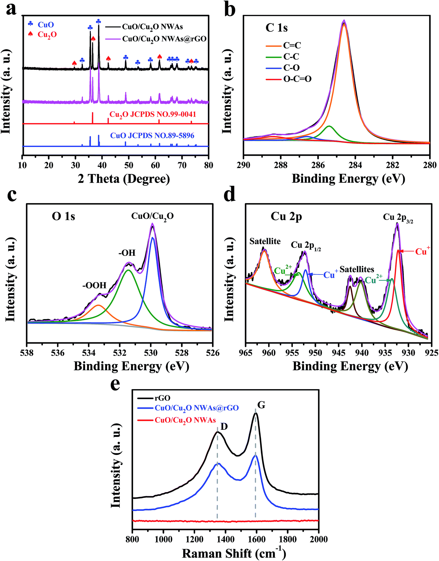 | ||
| Fig. 1 (a) XRD patterns of CuO/Cu2O NWAs; XPS spectra of (b) C 1s, (c) O 1s and (d) Cu 2p of CuO/Cu2O NWAs@rGO, (e) Raman spectra of rGO, CuO/Cu2O NWAs@rGO and CuO/Cu2O NWAs. | ||
XPS data were used to investigate chemical composition and the surface chemical states of CuO/Cu2O NWAs@rGO. Fig. 1b reveals the chemical states of carbon. The C 1s spectrum could be fitted into four peaks at 284.6, 285.4, 286.6, 288.4 eV, associated with graphitic sp2 carbon (C![[double bond, length as m-dash]](https://www.rsc.org/images/entities/char_e001.gif) C/C–C), C–O of hydroxyl or epoxy groups, and OC–O, respectively.24,25 The much stronger peaks related to graphitic sp2 carbon emerging from rGO skeleton suggests considerable content of graphitic carbon. The peak component at 286.6 eV was originated from the residual oxygen functionalities of rGO. The high energy peak component with low intensity at 288.4 eV was due to the environmental contamination to the sample. The O 1s spectrum in Fig. 1c consists of three oxygen contributions at 530.0, 531.4, and 533.4 eV, corresponding to oxygen bonded to Cu, carbonyl oxygen and oxygen atoms in hydroxyl groups, and oxygen atoms in carboxyl groups.26 Fig. 1d presents the Cu 2p XPS spectrum. Two Cu peaks at 932.2 and 952.0 eV, corresponding to the Cu 2p3/2 and Cu 2p1/2 peaks of Cu+, respectively, confirm the existence of Cu2O.27 The peaks at 933.5 and 953.5 eV with two extra shake-up satellites are assigned to the Cu 2p3/2 and Cu 2p1/2 peaks of Cu2+, respectively.28,29
C/C–C), C–O of hydroxyl or epoxy groups, and OC–O, respectively.24,25 The much stronger peaks related to graphitic sp2 carbon emerging from rGO skeleton suggests considerable content of graphitic carbon. The peak component at 286.6 eV was originated from the residual oxygen functionalities of rGO. The high energy peak component with low intensity at 288.4 eV was due to the environmental contamination to the sample. The O 1s spectrum in Fig. 1c consists of three oxygen contributions at 530.0, 531.4, and 533.4 eV, corresponding to oxygen bonded to Cu, carbonyl oxygen and oxygen atoms in hydroxyl groups, and oxygen atoms in carboxyl groups.26 Fig. 1d presents the Cu 2p XPS spectrum. Two Cu peaks at 932.2 and 952.0 eV, corresponding to the Cu 2p3/2 and Cu 2p1/2 peaks of Cu+, respectively, confirm the existence of Cu2O.27 The peaks at 933.5 and 953.5 eV with two extra shake-up satellites are assigned to the Cu 2p3/2 and Cu 2p1/2 peaks of Cu2+, respectively.28,29
The samples were further characterized by Raman spectroscopy (Fig. 1e). Compared to the smooth spectrum of CuO/Cu2O NWAs, two strikingly similar peaks of rGO and CuO/Cu2O NWAs@rGO (centered at ∼1580 cm−1 which represents the G-line and ∼1350 cm−1 representing the D-line) indicate the presence of rGO in CuO/Cu2O NWAs@rGO.
The surface morphologies of CuO/Cu2O NWAs and CuO/Cu2O NWAs@rGO were characterized by SEM (Fig. 2). The Cu foil shown in Fig. 2a has a smooth surface with unidirectional nicks. Fig. 2b and c report SEM images of nanowires grown with high density, as obtained by the oxidation of a Cu foil for 4 h at 600 °C. After heating the Cu foil in air for 4 h, the large-scale, dense, and directional CuO/Cu2O NWAs were directly grown in situ on the copper foil. The growth of the nanowires was preceded by a deformation of the substrate due to a straining force, with the formation of a hill and valley structure, in accordance with the literature.30 SEM analysis in cross-view reveals the absolutely straight nanowires, which allows us to determine that the average length of the nanowires is 25–35 μm (Fig. 2d). SEM images of CuO/Cu2O NWAs@rGO at different magnifications are shown in Fig. 2e–h. Plenty of ultrathin rGO nanosheets flock together and accumulate on the top of CuO/Cu2O NWAs like umbrellas (Fig. 2e). Furthermore, long and uniform CuO/Cu2O NWAs are coated with well-spread rGO nanosheets (Fig. 2f–h). Numerous tips of CuO/Cu2O NWAs stretch directionally and were closely wrapped by the rGO nanosheets, suggesting that the two materials are well combined through self-assembly procedure.
 | ||
| Fig. 2 SEM images of (a) Cu foil, and (b–d) CuO/Cu2O NWAs at different magnifications; (e–h) CuO/Cu2O NWAs@rGO at different magnifications. | ||
The structure of the sample obtained by annealing the copper foil at 600 °C in air for 4 h and CuO/Cu2O NWAs@rGO were further studied by TEM. Typical TEM images of a single CuO/Cu2O NWAs as synthesized are shown in Fig. 3a–c. The products have wire-like shapes and the nanowires are solid and straight with smooth surfaces and uniform diameters of ∼115.8 nm (Fig. 3a and b). The interlayer fringe of the selected area is 0.23 nm, which agrees well with the (111) plane of CuO (Fig. 3c),17,28 whereas there is no interlayer fringe associated with Cu2O. Thus, these nanowires are composed of CuO phase and the underlying film is Cu2O.31 As seen from Fig. 3d, wrinkled and little aggregated rGO nanosheets were observed. The thickness of the ultrathin rGO nanosheets is about 40 nm.
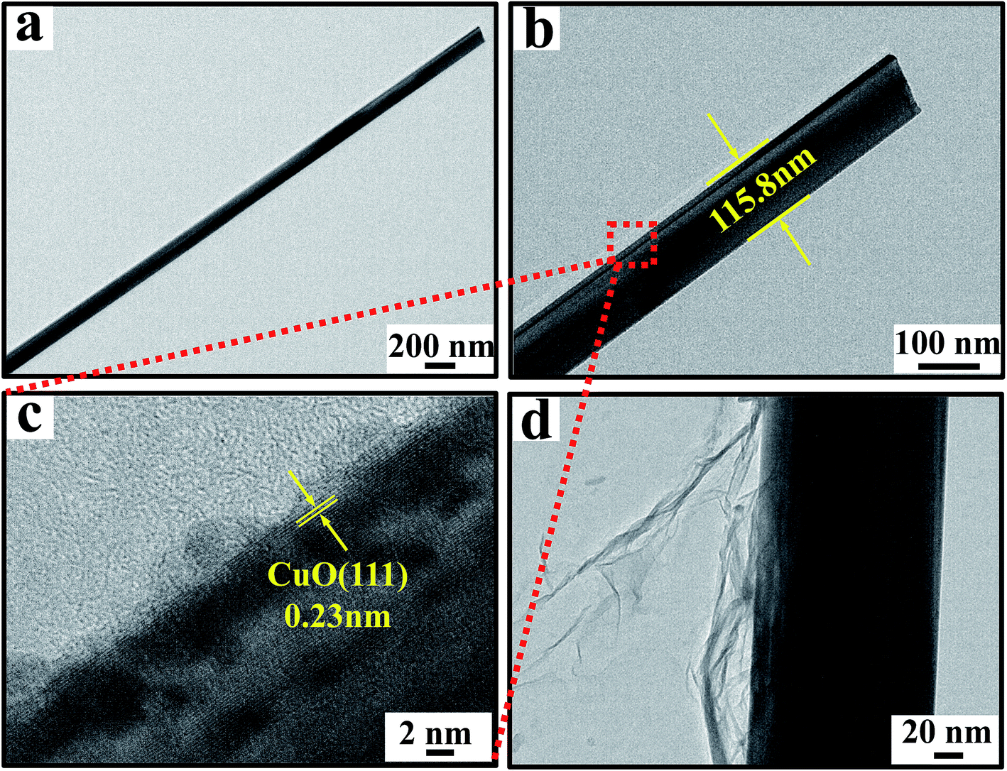 | ||
| Fig. 3 Low- and high-magnification TEM images of (a–c) CuO/Cu2O NWAs; (d) CuO/Cu2O NWAs@rGO. | ||
3.2. Photocatalytic activity
Electrochemical impedance spectroscopy (EIS) was further used to investigate the photogenerated charge separation process. Fig. 4a shows the EIS Nyquist plots of CuO/Cu2O NWAs and CuO/Cu2O NWAs@rGO. A smaller arc radius of the EIS Nyquist plot suggests an effective separation of photogenerated electron–hole pairs and fast interfacial charge transfer.32,33 Evidently, the diameters of the arc radius of CuO/Cu2O NWAs@rGO is smaller than that of CuO/Cu2O NWAs, further confirming that the ultrathin layer of rGO with good conductivity facilitates the electron migration to the reaction sites on the surface of the composite.34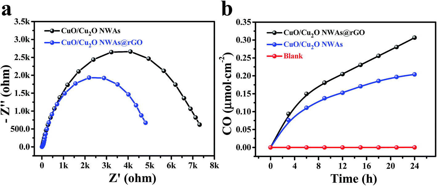 | ||
| Fig. 4 (a) EIS of CuO/Cu2O NWAs and CuO/Cu2O NWAs@rGO electrodes; (b) CO yield by photocatalysis of CuO/Cu2O NWAs and CuO/Cu2O NWAs@rGO. | ||
CuO/Cu2O NWAs and CuO/Cu2O NWAs@rGO were tested for the photocatalytic reduction CO2 with H2O under simulated solar irradiation. Fig. 4a shows the evolution of the main product (CO) as function of irradiation time. No CO is observed in the absence of photocatalyst, whereas CuO/Cu2O NWAs and CuO/Cu2O NWAs@rGO exhibits photocatalytic activity. The yields of CO over these two samples increase with the irradiation time. Significantly, CuO/Cu2O NWAs@rGO demonstrates a higher photocatalytic performance compared to CuO/Cu2O NWAs, and these two materials reach a CO yield of 0.31 and 0.20 μmol cm−2, respectively, after 24 h of visible light irradiation.
CuO nanomaterials absorb visible light of solar spectrum very efficiently and generate electron–hole pairs. However, the fast recombination of electron–hole pairs (which is crucial for the electron-dominated reduction reaction) owing to the narrow band gap makes them unavailable for photocatalytic reaction.5 Therefore, CuO/Cu2O NWAs showed lower photocatalytic conversion. CuO/Cu2O NWAs@rGO revealed improved photocatalytic activity, most likely ascribed to the improvement of the conductivity of CuO/Cu2O NWAs@rGO by introducing rGO and the nearly equal position of conduction band of CuO (∼4.1 eV) and LUMO of graphene (∼4.4 eV).35,36 rGO platelets with high conductivity provide a direct pathway for efficient separation and transfer of photoexcited electrons, which means that the photo-generated electron in the conduction band of CuO/Cu2O NWAs can easily transfer to the rGO nanosheets, thus inhibiting the recombination of electron–hole pairs and facilitating the electron transport to the catalytic sites for the reduction of CO2 to CO. Photo-generated holes can oxidize the water molecules to give protons (H+).11 Furthermore, the existence of mixture of Cu+/Cu2+ oxidation states on the surface of catalysts according to XPS analysis. Cu+ may also can interact with holes and suppress the combination of photogenerated electrons and holes.
4. Conclusions
In conclusion, the large-scale, dense, and directional CuO/Cu2O nanowires on Cu foil were grafted by ultrathin rGO nanosheets. CuO/Cu2O NWAs@rGO was used for the photocatalytic reduction of CO2 to CO under visible light irradiation. XRD and XPS analysis confirm that tCuO/Cu2O NWAs@rGO has a heterojunction structure of Cu+/Cu2+. Meanwhile, SEM and TEM results show that the ultrathin rGO nanosheets are like umbrellas coated on the CuO/Cu2O nanowires, which can enhance the conductivity of CuO/Cu2O NWAs@rGO. CuO/Cu2O NWAs@rGO exhibited enhanced photocatalytic performance compare to CuO/Cu2O NWAs in the reduction of CO2 with H2O to CO under simulated solar irradiation.Conflicts of interest
There are no conflicts to declare.Acknowledgements
This work was financially supported by China National Natural Science Foundation (51772051, 51528202 and 51671136), Natural Science Foundation of Guangdong Province (2016A030310127), and “Shu Guang” project (13SG46) supported by Shanghai Municipal Education Commission and Shanghai Education Development Foundation.References
- T. Seki, Y. Kokubo, S. Ichikawa, T. Suzuki, Y. Kayaki and T. Ikariya, Chem. Commun., 2009, 3, 349–351 RSC.
- J. D. Figueroa, T. Fout, S. Plasynski, H. Mcilvried and R. D. Srivastava, Int. J. Greenhouse Gas Control, 2008, 2, 9–20 CrossRef CAS.
- J. Mao, K. Li and T. Y. Peng, Catal. Sci. Technol., 2013, 3, 2481–2498 CAS.
- W. Fan, Q. Zhang and Y. Wang, Phys. Chem. Chem. Phys., 2013, 15, 2632–2649 RSC.
- R. Gusain, P. Kumar, O. P. Sharma, S. L. Jain and O. P. Khatri, Appl. Catal., B, 2016, 181, 352–362 CrossRef CAS.
- J. Qin, S. Wang, H. Ren, Y. Hou and X. Wang, Appl. Catal., B, 2015, 179, 1–8 CrossRef CAS.
- W. Zou, L. Zhang, L. Liu, X. Wang, J. Sun, S. Wu, Y. Deng, C. Tang, F. Gao and L. Dong, Appl. Catal., B, 2016, 181, 495–503 CrossRef CAS.
- L. C. Sim, K. H. Leong, P. Saravanan and S. Ibrahim, Appl. Surf. Sci., 2015, 358, 122–129 CrossRef CAS.
- W. N. Wang, W. J. An, B. Ramalingam, S. Mukherjee, D. M. Niedzwiedzki, S. Gangopadhyay and P. Biswas, J. Am. Chem. Soc., 2012, 134, 11276–11281 CrossRef CAS PubMed.
- X. Feng, J. D. Sloppy, T. J. Latempa, M. Paulose, S. Komarneni, N. Bao and C. A. Grimes, J. Mater. Chem., 2011, 21, 13429–13433 RSC.
- J. Yu, J. Low, W. Xiao, P. Zhou and M. Jaroniec, J. Am. Chem. Soc., 2014, 136, 8839–8842 CrossRef CAS PubMed.
- H. C. Yang, H. Y. Lin, Y. S. Chien, C. S. Wu and H. H. Wu, Catal. Lett., 2009, 131, 381–387 CrossRef CAS.
- K. Kočí, L. Obalová, L. Matějová, D. Plachá, Z. Lacný, J. Jirkovský and O. Šolcová, Appl. Catal., B, 2009, 89, 494–502 CrossRef.
- S. Deng, V. Tjoa, H. M. Fan, H. R. Tan, D. C. Sayle, M. Olivo, S. Mhaisalkar, J. Wei and C. H. Sow, J. Am. Chem. Soc., 2012, 134, 4905–4917 CrossRef CAS PubMed.
- S. Brittman, Y. Yoo, N. P. Dasgupta, S. I. Kim, B. Kim and P. Yang, Nano Lett., 2014, 14, 4665–4670 CrossRef CAS PubMed.
- A. Dubale, W. N. Su, A. Tamirat, C. J. Pan, B. Aragaw, H. M. Chen, C. H. Chen and B. J. Hwang, J. Mater. Chem. A, 2014, 2, 18383–18397 CAS.
- J. Zhao, X. Shu, Y. Wang, C. Yu, J. Zhang, J. Cui, Y. Qin, H. Zheng, J. Liu, Y. Zhang and Y. Wu, Surf. Coat. Technol., 2016, 299, 15–21 CrossRef CAS.
- H. Wang, J. Xu, H. Jing, J. Zhang, P. Li and F. Lu, Acta Chim. Sin., 2013, 71, 941 CAS.
- C. Jie, S. H. Shen, P. H. Guo, W. Meng, P. Wu, X. X. Wang and L. J. Guo, Appl. Catal., B, 2014, 152–153, 335–341 Search PubMed.
- X. Zhao, Y. Tan, F. Wu, H. Niu, Z. Tang, Y. Cai and J. P. Giesy, Sci. Total Environ., 2016, 571, 380–387 CrossRef CAS PubMed.
- Q. Xiang, J. Yu and M. Jaroniec, Chem. Soc. Rev., 2011, 41, 782–796 RSC.
- Y. Z. Zhang, G. Q. Mo, X. W. Li, W. D. Zhang, J. Q. Zhang, J. S. Ye, X. D. Huang and C. Z. Yu, J. Power Sources, 2011, 196, 5402–5407 CrossRef CAS.
- L. J. Seok, K. H. You and P. C. Beum, Adv. Mater., 2012, 24, 1084–1088 CrossRef PubMed.
- L. Liu, Z. Liu, A. Liu, X. Gu, C. Ge, F. Gao and L. Dong, ChemSusChem, 2014, 7, 618–626 CrossRef CAS PubMed.
- D. Yang, A. Velamakanni, G. Bozoklu, S. Park, M. Stoller, R. D. Piner, S. Stankovich, I. Jung, D. A. Field and C. A. Ventrice, Carbon, 2009, 47, 145–152 CrossRef CAS.
- I. A. Khan, A. Badshah, M. A. Nadeem, N. Haider and M. A. Nadeem, Int. J. Hydrogen Energy, 2014, 39, 19609–19620 CrossRef CAS.
- H. Li, Y. Lei, Y. Huang, Y. Fang, Y. Xu, L. Zhu and X. Li, J. Nat. Gas Chem., 2011, 20, 145–150 CrossRef CAS.
- K. Wang, X. Dong, C. Zhao, X. Qian and Y. Xu, Electrochim. Acta, 2015, 152, 433–442 CrossRef CAS.
- Q. X. Qing, M. Masahiro, S. Kayano, M. Masafumi, L. Min, L. Yue, L. Ding, S. Yoshiki, H. Yasuhiro, K. Yasushi and H. Kazuhito, ACS Nano, 2011, 6, 1609–1618 Search PubMed.
- M. Kaur, K. P. Muthe, S. K. Despande, S. Choudhury, J. B. Singh, N. Verma, S. K. Gupta and J. V. Yakhmi, J. Cryst. Growth, 2006, 289, 670–675 CrossRef CAS.
- S. C. Vanithakumari, S. L. Shinde and K. K. Nanda, Mater. Sci. Eng., B, 2011, 176, 669–678 CrossRef CAS.
- X. J. Bai, L. Wang, R. L. Zong and Y. F. Zhu, J. Phys. Chem. C, 2013, 117, 9952–9961 CAS.
- X. Q. An, J. C. Yu and J. W. Tang, J. Mater. Chem. A, 2013, 2, 1000–1005 Search PubMed.
- X. An, K. Li and J. Tang, ChemSusChem, 2014, 7, 1086–1093 CrossRef CAS PubMed.
- N. L. Yang, J. Zhai, D. Wang, Y. S. Chen and L. Jiang, ACS Nano, 2010, 4, 887–894 CrossRef CAS PubMed.
- D. Chauhan, V. R. Satsangi, S. Dass and R. Shrivastav, Bull. Mater. Sci., 2006, 29, 709–716 CAS.
| This journal is © The Royal Society of Chemistry 2017 |