
 Open Access Article
 This Open Access Article is licensed under a
 Creative Commons Attribution 3.0 Unported Licence
Perchlorate ion doped polypyrrole coated ZnS sphere composites as a sodium-ion battery anode with superior rate capability enhanced by pseudocapacitance†
Tianyi Houa,
Guojie Tanga,
Xiaohong Sun *a,
Shu Caia,
Chunming Zheng*b and
Wenbin Hua
*a,
Shu Caia,
Chunming Zheng*b and
Wenbin Hua
aSchool of Materials Science and Engineering, Key Laboratory of Advanced Ceramics and Machining Technology of Ministry of Education, Tianjin University, Tianjin 300072, PR China. E-mail: sunxh@tju.edu.cn
bState Key Laboratory of Hollow-fiber Membrane Materials and Membrane Processes, School of Environmental and Chemical Engineering, Tianjin Polytechnic University, Tianjin 300387, PR China. E-mail: zhengchunming@tjpu.edu.cn
First published on 11th September 2017
Abstract
Considering the inferior rate capability of conversion-type transition-metal sulphides (TMSs) caused by severe volume expansion and poor electronic conductivity, a composite of perchlorate ion (ClO4−) doped polypyrrole (PPy) coated ZnS spheres (denoted as ZnS@d-PPy) has been synthesized via a soft chemistry method. Benefiting from the improved conductivity, the protection of the PPy coating and ClO4− doping, ZnS@d-PPy exhibits decent cycling performance (419 mA h g−1 after 30 cycles at 100 mA g−1) and superior rate capability (203 mA h g−1 at 4 A g−1), which is enhanced by pseudocapacitance when being applied in sodium-ion batteries (SIBs).
1. Introduction
Sodium-ion batteries (SIBs) have drawn tremendous attention as a promising alternative to lithium-ion batteries (LIBs) because of the abundance and low cost of sodium resources.1–4 The similar electrochemical reaction mechanism of Na+ in SIBs to that of Li+ in LIBs ensures the feasibility of SIBs.1,5 Anode materials, an essential component of SIBs, often suffer from a low specific capacity5,6 and one of the primary reasons is Na+ (radius 1.06 Å, mass 23.0 g mol−1) is larger and heavier than Li+ (radius 0.76 Å, mass 6.9 g mol−1).7 For example, graphite cannot effectively intercalate sodium due to its small interlayer distance and a critical minimum spacing of 0.37 nm between graphitic layers has been demonstrated for carbon materials.8,9 Some researchers made efforts on hard carbon materials because of their large interlayer distance; however, most of them delivered a reversible capacity below 300 mA h g−1.8 Although exhibiting good cyclability, other intercalation-type anode materials such as expanded graphite,9 Na2Ti3O7 (ref. 10 and 11) and NaTi2(PO4)3 (ref. 12) also have the same problem of a low capacity. By contrast, alloying and conversion anode materials with relatively high theoretical capacity are proposed to address this problem. Although silicon, an important alloying anode material for LIBs, does not alloy with sodium at room temperature, tin is a promising alloying anode material for SIBs with an average voltage of 0.3 V and a theoretical capacity of 790 mA h g−1.4 Conversion anode materials such as Fe2O3 (ref. 5) and Co3O4 (ref. 13) have been also extended to SIBs due to their multiple electron reactions accompanied with high theoretical specific capacities.1 Recently, transition-metal sulphides (TMSs) anode materials with conversion reaction mechanisms have been paid much attention for their higher theoretical capacities,6 unique physical and chemical properties.14 Among various TMSs, ZnS is a competitive candidate for SIB anode materials because of its high theoretical capacity (550 mA h g−1), low cost, non-toxic nature14–16 and has been carefully investigated in LIBs.17–22 However, it is always limited by a quick capacity fading and poor rate capability caused by low electronic conductivity and severe volume change during discharge/charge processes.15,22 Synthesizing hollow structure is a good approach to alleviate the volume-expansion issue and hollow interiors can effectively accommodate volume variation during discharge/charge processes.23,24 N. Du et al. synthesized ZnS hollow spheres used SiO2 spheres as templates and a layer-by-layer approach for applying in LIBs.25 However, hollow structure anode materials are still hindered by a low volumetric energy density and side reactions due to their large void space and high surface areas.23Another general approach is to fabricate composites of ZnS and carbonaceous materials such as graphene,14,22 porous carbon21 and nitrogen-doped carbon.15 W. Qin et al. elevated the specific capacity of active materials by embedded ZnS nanoparticles in reduced graphene oxide, delivering a reversible capacity of 610 mA h g−1 at 100 mA g−1.14 J. Li et al. have reported urchinlike ZnS microspheres decorated with N-doped carbon derived from polydopamine and they exhibited superior electrochemical performance as an anode material for both LIBs and SIBs.15 These results demonstrate that conductive coating is a valid method of improving the behavior of ZnS-based anode materials. Polypyrrole (PPy) as a well-known conductive polymer has been extensively applied in the battery field (e.g., lithium sulfur batteries,26 LIBs27–29 and SIBs30–32) with simple synthesis and possibly works on ZnS-based anodes. Meanwhile, PPy layers are also highly stretchable and flexible, allowing free volume variation and accommodating volume expansion of anodes during sodiation/desodiation processes.32 However, too much PPy coating will lead to a lower actual capacity. Perchlorate ions (ClO4−) doping is an effective method to increase the conductivity33 and acts as redox-active sites to improve the capacity of PPy coated active materials reported by W. Li et al. on Prussian blue analog (PBA) cathodes of SIBs.31 it is also meaningful to investigate the behavior of d-PPy coating in anode materials.
Herein, we report a composite of thin-layer (∼15 nm) ClO4− doped PPy (d-PPy) coated ZnS spheres (denoted as ZnS@d-PPy) via a soft chemistry method. The as-prepared ZnS@d-PPy exhibits superior rate capability. Further kinetic analyses reveal that the behavior of ZnS@d-PPy is enhanced by pseudocapacitance as well as the effectiveness of d-PPy coating improving the conductivity of the composite and maintaining the structural integrity.
2. Experimental
2.1. Material synthesis
The synthesis consists of two steps: the preparation of ZnS spheres and d-PPy coating process. The preparation of ZnS followed the previous work34 with the concentration of thiourea was 1 M. The d-PPy coating process was modified from the previous research.26,31 100 mg above prepared ZnS spheres were dispersed in 40 ml dimethyl carbonate (DMC) by ultrasound and then 24 mg NaClO4 and 20 ml DMC solution of pyrrole (2.25 mM) was added. Next, 10 ml DMC solution of FeCl3 (0.25 mM) was slowly added as an oxidant under vigorous stirring in ice bath for 1 h. Finally, ZnS@d-PPy was collected by centrifugation and washed by ethanol for several times. Then as-prepared powder was dried at 60 °C in a vacuum oven overnight. For comparison, the composite of ZnS spheres coated by pure PPy (ZnS@PPy) was synthesized by the similar method without adding of NaClO4.2.2. Characterization
ZnS@d-PPy was characterized by X-ray diffraction (XRD, Bruker D8, Cu Ka radiation), Fourier transform infrared spectroscopy (FTIR, BIO-RAD FTS3000), Thermogravimetric analysis (TGA, STA449C), Field-emission scanning electron microscopy (SEM, JEOL JEM-2100F) and Transmission electron microscopy (TEM, JEOL JEM-2100F).2.3. Electrochemical measurements
The electrodes were prepared by pasting slurries composed of 70% active materials, 20% carbon black and 10% poly (vinylidene fluoride) (PVDF) in the N-methyl-2-pyrrolidone (NMP) on copper foils and cutting into 10 mm disks with an active material loading rate of around 0.8 mg cm−2. CR2032 coin-type cells were assembled with sodium foils as both reference and counter electrodes and glass fiber membranes (Whatman) as separators. The electrolyte was 1 M sodium trifluomethanesulfonate (NaSO3CF3) in diglyme (DGM). Galvanostatic tests were cycled between 0.01–3 V at room temperature by using the LAND CT2001A battery-testing instrument. The specific capacity was calculated based on the total mass of active materials. Cyclic voltammograms (CVs) were performed between 0–3 V on an electrochemical workstation (CHI660C, Chenhua, Shanghai, China). Electrochemical impedance spectroscopy (EIS) measurements were conducted by employing an AC voltage of 5 mV amplitude with a frequency range from 100 kHz to 0.01 Hz.3. Results and discussion
Fig. 1a shows the X-ray diffraction (XRD) patterns of ZnS and ZnS@d-PPy. All the main peaks in the XRD patterns can be indexed to the standard JCPDS no. 05-0492, indicating a hexagonal ZnS with the P63mc space group (wurtzite structures).34 The similarity of XRD patterns between ZnS and ZnS@d-PPy suggests that the polymerization of pyrrole with FeCl3 oxidant and NaClO4 dopant cause no damage to crystalline structure of ZnS and no detectable impurity is introduced. In Fig. 1b the intensity of the spectrum of ZnS@d-PPy is slightly lower than that of ZnS and the obvious bands at ∼1560 and ∼936 cm−1 of ZnS@d-PPy can be assigned to C–C stretching vibration in pyrrole ring and perchlorate ions, respectively, indicating the outermost coating of the d-PPy layer.29,31,33 The mass ratio of d-PPy is 8.9% for ZnS@d-PPy from the TGA curves (ESI, Fig. S1†), which indicates a low d-PPy content of the ZnS@d-PPy composite.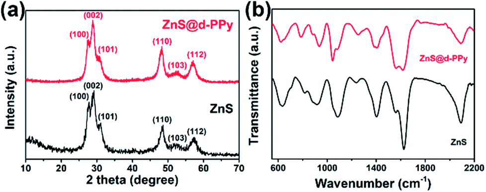 | ||
| Fig. 1 (a) XRD patterns and (b) FTIR spectra of ZnS and ZnS@d-PPy. | ||
Fig. 2 shows the SEM and TEM images of ZnS and ZnS@d-PPy. From Fig. 2a, it can be seen that ZnS spheres have a homogeneous size distribution of about 300 nm. And ZnS nanograins (10–40 nm) can be found on the surface of ZnS spheres after zooming in (Fig. 2b). After d-PPy coating, the spherical diameter of ZnS@d-PPy spheres is still uniform and similar to ZnS spheres (Fig. 2d). The surface of ZnS@d-PPy spheres become smooth, indicating the cover of d-PPy layers (Fig. 2e). ZnS@PPy without adding of NaClO4 has an identical morphology with ZnS@d-PPy (ESI, Fig. S2†), suggesting ClO4− has less impact on d-PPy coating processes. More details can be found in TEM images of ZnS (Fig. 2c) and ZnS@d-PPy (Fig. 2f), where ZnS nanograins are uniformly distributed in a spherical particle with a mesoporous property (ESI, Fig. S3†). Fig. 2f depicts that ZnS is coated by a thin d-PPy layer with an average thickness of about 15 nm. By comparison, d-PPy coating bring no significant change to the morphology of ZnS spheres.
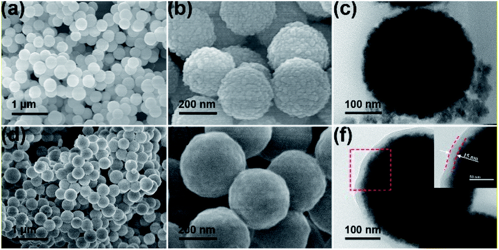 | ||
| Fig. 2 (a, b) SEM and (c) TEM images of ZnS; (d, e) SEM and (f) TEM images of ZnS@d-PPy. Inset of (f) is the high-magnification image of the selected area in the red dash line. | ||
The electrochemical performance of ZnS and ZnS@d-PPy composite electrodes were investigated by using CR2032 coin-type Na half cells. Fig. 3a and b show the CV curves of ZnS and ZnS@d-PPy versus Na+/Na between 0 and 3 V at a scan rate of 0.1 mV s−1. For ZnS, in the first cathodic scan, a weak peak at around 0.60 V corresponds to Na+ insertion into ZnS and the following strong peaks at 0.35 V and 0.10 V are assigned to the conversion reaction of ZnS and the formation of solid electrolyte interface (SEI) layers.14–16 The situation is similar for ZnS@d-PPy while only one merged strong peak appears at around 0.34 V. In second and third cathodic scans, three peaks can still be found at about 0.62, 0.45 and 0.03 V for both ZnS and ZnS@d-PPy. As for anodic scans, peaks between 0.50 and 1.30 V can be attributed to several steps of extraction of Na+ from Na2S and the formation of ZnS. A broad peak at around 1.50 V only appears in CV curves of ZnS@d-PPy is most likely due to ClO4− doping providing redox-active sites.31 The possible sodiation/desodiation mechanism of ZnS is described below:
| 2Na+ + ZnS + 2e− ↔ Na2S + Zn | (1) |
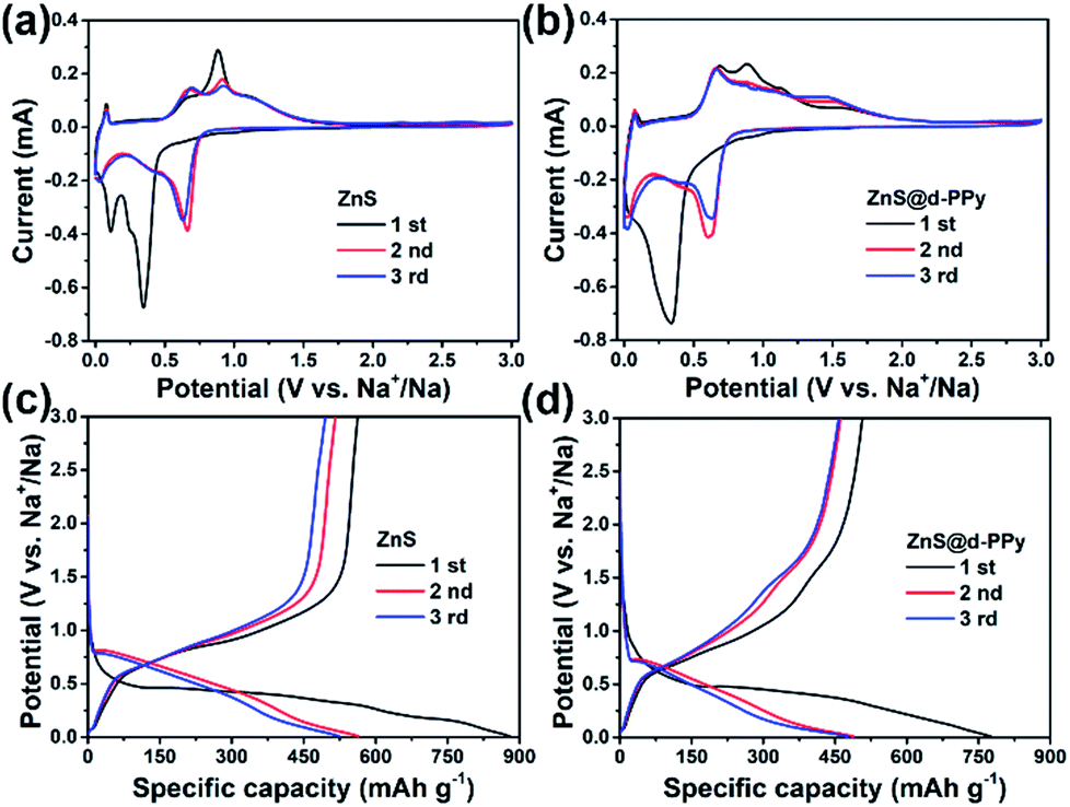 | ||
| Fig. 3 CV curves of (a) ZnS, (b) ZnS@d-PPy between 0 and 3 V at a scan rate of 0.1 mV s−1; discharge/charge voltage profiles of (c) ZnS, (d) ZnS@d-PPy between 0.01 and 3 V at 100 mA g−1 for the initial three cycles. | ||
Fig. 3c and d show the discharge/charge profiles of ZnS and ZnS@d-PPy. For pure ZnS, the initial discharge curve presents two plateaus below 0.5 V while there is one major plateau for that of ZnS@d-PPy and it is similar to the first cathodic scan in CV curves of ZnS and ZnS@d-PPy, corresponding to the conversion reaction of ZnS. In following discharge processes, the platform voltage elevates to around 0.7 V for both ZnS and ZnS@d-PPy in discharge/charge profiles and the similar condition also occurs in CV curves, mainly owing to the irreversible formation of SEI layers and irreversible changes of ZnS after the initial sodiation/desodiation process, which still needs further investigation. In Fig. 3c, pure ZnS delivers a discharge and charge capacity of 880 and 563 mA h g−1 in the first cycle at 100 mA g−1 with a coulombic efficiency of 63.9%. After d-PPy coating, the initial discharge and charge capacity of ZnS@d-PPy is 775 and 507 mA h g−1. And the coulombic efficiency is 65.4%, which is slightly higher than pure ZnS. The capacity loss of the first cycle is mostly out of the formation of SEI layers.14,15 The main reason for the higher initial capacity of ZnS than that of ZnS@d-PPy is because that the specific capacity of ZnS@d-PPy is calculated on the basis of the total mass of ZnS@d-PPy and d-PPy has a lower specific capacity than ZnS.31
Fig. 4a shows the cycling performance of ZnS, ZnS@PPy and ZnS@d-PPy between 0.01 and 3 V at 100 mA g−1. As we can see, ZnS@d-PPy has the best cycling performance among three samples, delivering 419 mA h g−1 after 30 cycles (ESI, Fig. S4†). ZnS@PPy and ZnS@d-PPy show better cycling stability than pure ZnS (64 mA h g−1 after 30 cycles), indicating PPy coating has a positive effect as a conductive and buffer layer accommodating the volume expansion and protecting ZnS spheres form being destroyed during discharge/charge processes. Compared with ZnS@PPy (266 mA h g−1 after 30 cycles), ZnS@d-PPy retains a higher discharge capacity over 30 cycles, demonstrating ClO4− doping is effective and provides more capacity to the composite than pure PPy coating. Fig. 4b displays the rate capability of ZnS and ZnS@d-PPy. ZnS@d-PPy exhibits superior rate capability and delivers discharge capacities of 465, 441, 355, 302, 249 and 203 mA h g−1 at 100, 200, 500, 1000, 2000 and 4000 mA g−1, respectively. And after the current returns to 100 mA g−1, a capacity retention of about 98% is achieved (455 mA h g−1) while that of ZnS is ∼77%. Discharge/charge voltage profiles of each current can also be seen in Fig. S5 ESI.† Meanwhile, the long-term cycling performance of ZnS@d-PPy was investigated at a high current density of 2 A g−1 (Fig. 4c). After 100 cycles, a discharge capacity of 148 mA h g−1 with a high coulombic efficiency (98.5%) can be still retained. More evidence can be found in Nyquist plots (Fig. 4d), where ZnS@d-PPy exhibits lowest charge-transfer resistance (5.6 Ω) than that of ZnS (19.7 Ω) and ZnS@PPy (6.4 Ω) after initial cycle at 100 mA g−1. It suggests that d-PPy coating can effectively enhance the conductivity of the ZnS@d-PPy composite.
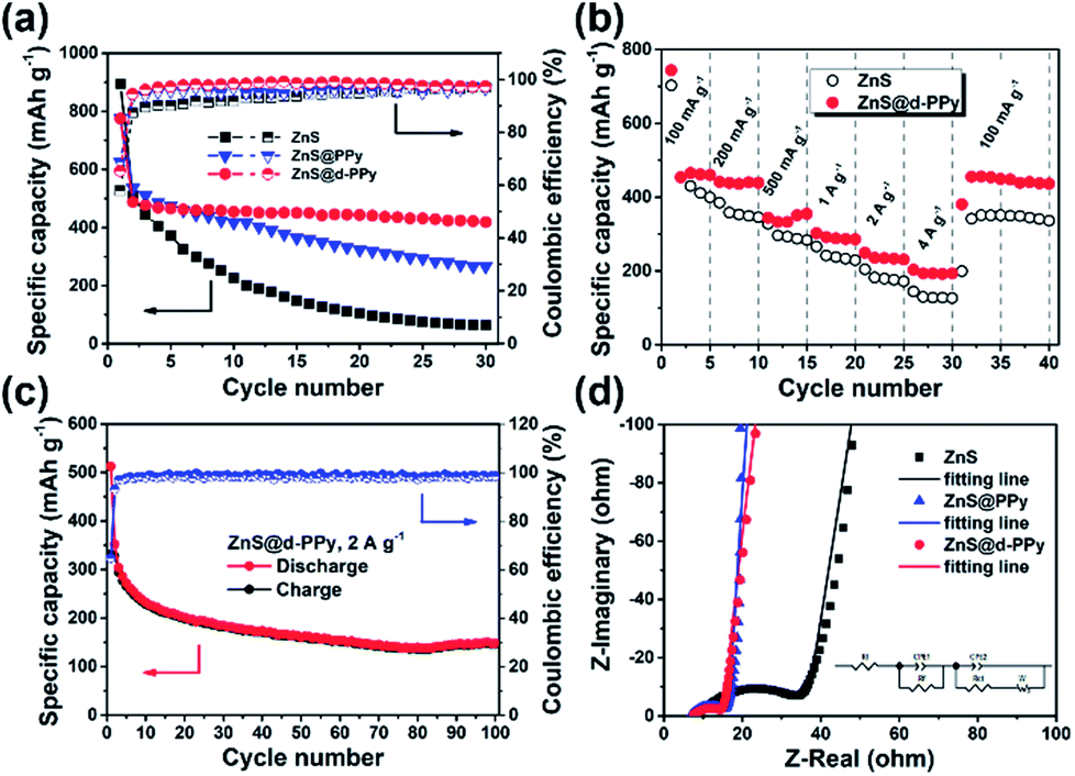 | ||
| Fig. 4 (a) Cycling performance of ZnS, ZnS@PPy and ZnS@d-PPy at 100 mA g−1; (b) rate capability of ZnS and ZnS@d-PPy; (c) long-term cycling stability of ZnS@d-PPy at 2 A g−1; (d) partial Nyquist plots of ZnS, ZnS@PPy and ZnS@d-PPy after initial cycle. The equivalent circuit is shown as inset. | ||
Considering superior rate capability of ZnS@d-PPy, it can be theorized that electrochemical capacitance effects have an important impact on fast discharge/charge processes.35,36 Herein, a quantitative analysis based on CV tests at various scan rates was used for further investigating the reaction kinetic of ZnS@d-PPy and distinguishing between capacitive and diffusion-controlled contributions to the total capacity. The CV curves at scan rates of 0.1, 0.3, 0.6, 0.9 and 1.2 mV s−1 are shown in Fig. 5a. The shapes of each curve are identical with peak currents gradually increasing as scan rates ascending. The measured current (i) obeys a power law relationship with the scan rate (ν) according to
| i = aνb. | (2) |
 | ||
| Fig. 5 (a) CV curves at various scan rates. (b) Determination of corresponding b-values of different redox states; (c) CV curves with separation of capacitive currents (red shaded region) among total currents (solid line) and (d) contribution ratios of the capacitive and diffusion-controlled capacity at various scan rates. | ||
To distinguish quantitatively the capacitive contribution from the current response, eqn (2) is rewritten as
| i(V) = k1ν + k2ν1/2. | (3) |
| i(V)/ν1/2 = k1ν1/2 + k2 | (4) |
By plotting ν1/2 vs. i/ν1/2, k1 and k2 can be derived from values of the slopes and intercepts. As in Fig. 5c, CV curves and capacitive contributions (shaded area) of each scan rate are shown. And as the scan rate increases from 0.1 to 1.2 mV s−1, the proportion of surface capacitive capacity upgrades from 59.3 to 90.0% (Fig. 5d). The high contribution of the capacitive charge storage of ZnS@d-PPy may be accounted for that d-PPy coating enhances the conductivity of the composite and provides more redox-active sites31 as well as ZnS nanograins shorten the Na+ diffusion length.6,16 The capacitive contribution is mainly provided by faradic charge-transfer process through surface atoms, referred to as pseudocapacitance, generally.16,37 As a result, the dominated pseudocapacitive Na+ storage mechanism enhances the high-rate capability of ZnS@d-PPy.
Fig. 6 shows the structure evolution of ZnS and ZnS@d-PPy investigated by ex situ SEM and TEM images. Combined with the schematic illustration of ZnS (Fig. 6a) and corresponding SEM (Fig. 6b) and TEM (Fig. 6c) images, it is clear that the structure of ZnS spheres collapse and significantly aggregate after cycles. That is because the sodiation of ZnS spheres causes drastic volume expansion and leads to the decomposition of ZnS spheres and deterioration of pure ZnS electrodes. In comparison, ZnS@d-PPy spheres still maintain their original core–shell structure without obvious changes (Fig. 6d and e) benefitting from the stretchable d-PPy coating accommodating volume expansion and stabilizing the structure of ZnS@d-PPy upon long-term cycling. All these demonstrate d-PPy coating can efficiently protect ZnS spheres from being wrecked and accommodate large volume expansion during sodiation even at a large current of 2 A g−1.
 | ||
| Fig. 6 (a) Schematic illustrations of structure evolution of ZnS and ZnS@d-PPy after 100 cycles at 2 A g−1 and corresponding (b), (d) SEM and (c), (e) TEM images, respectively. | ||
The superior rate capability and good cyclability of ZnS@d-PPy can be attributed to two features by reviewing above results and analyses. First, the stretchable d-PPy coating increases the electronic conductivity of ZnS and act as a buffer layer to accommodate the volume expansion and maintain the structural integrity during discharge/charge processes. Second, d-PPy can provide more redox-active sites increasing the specific capacity and enhancing the electrochemical performance of ZnS@d-PPy composites, especially for the rate capability. Thereinto, ClO4− doping plays a crucial role for further improving the electronic conductivity of PPy and provides redox-active sites for sodium storage. Consequently, ZnS@d-PPy presents enhanced and efficient pseudocapacitive behavior and delivers a high-rate performance compared to the previous work of ZnS-based anodes in SIBs (Table S1†). In addition, the usage of ether-based NaSO3CF3/diglyme electrolyte is also beneficial to ZnS anodes according to previous work.16,38
4. Conclusions
In summary, a composite of ClO4− doped PPy coated ZnS spheres (∼300 nm) has been successfully synthesized via a soft chemistry method with a d-PPy layer thickness of about 15 nm. When being applied as an anode material for SIBs, ZnS@d-PPy achieves a high specific capacity of 419 mA h g−1 at 100 mA g−1 after 30 cycles. More importantly, ZnS@d-PPy exhibits a superior rate capability and delivers a discharge capacity of 203 mA h g−1 at 4 A g−1, and a capacity retention of about 98% is achieved after the current returns to 100 mA g−1. This work provides a general approach for elevating electrochemical performance of anode materials with severe volume variation upon cycling and ClO4− doping also has potential to extend to the syntheses of other anode materials.Conflicts of interest
There are no conflicts to declare.Acknowledgements
The authors acknowledge the financial support by the National Natural Science Foundation of China, NSFC (51572192, 51472179, 51772205, 51772208) and General Program of Municipal Natural Science Foundation of Tianjin (17JCYBJC17000, 17JCYBJC22700).Notes and references
- S. W. Kim, D. H. Seo, X. H. Ma, G. Ceder and K. Kang, Adv. Energy Mater., 2012, 2, 710–721 CrossRef CAS.
- H. L. Pan, Y. S. Hu and L. Q. Chen, Energy Environ. Sci., 2013, 6, 2338–2360 CAS.
- N. Yabuuchi, K. Kubota, M. Dahbi and S. Komaba, Chem. Rev., 2014, 114, 11636–11682 CrossRef CAS PubMed.
- D. Kundu, E. Talaie, V. Duffort and L. F. Nazar, Angew. Chem., Int. Ed., 2015, 54, 3431–3448 CrossRef CAS PubMed.
- N. Zhang, X. P. Han, Y. C. Liu, X. F. Hu, Q. Zhao and J. Chen, Adv. Energy Mater., 2015, 5, 1401123 CrossRef.
- L. Zhou, K. Zhang, J. Sheng, Q. An, Z. Tao, Y.-M. Kang, J. Chen and L. Mai, Nano Energy, 2017, 35, 281–289 CrossRef CAS.
- M. D. Slater, D. Kim, E. Lee and C. S. Johnson, Adv. Funct. Mater., 2013, 23, 947–958 CrossRef CAS.
- Y. L. Cao, L. F. Xiao, M. L. Sushko, W. Wang, B. Schwenzer, J. Xiao, Z. M. Nie, L. V. Saraf, Z. G. Yang and J. Liu, Nano Lett., 2012, 12, 3783–3787 CrossRef CAS PubMed.
- Y. Wen, K. He, Y. J. Zhu, F. D. Han, Y. H. Xu, I. Matsuda, Y. Ishii, J. Cumings and C. S. Wang, Nat. Commun., 2014, 5, 4033 CAS.
- H. L. Pan, X. Lu, X. Q. Yu, Y. S. Hu, H. Li, X. Q. Yang and L. Q. Chen, Adv. Energy Mater., 2013, 3, 1186–1194 CrossRef CAS.
- A. Rudola, K. Saravanan, C. W. Mason and P. Balaya, J. Mater. Chem. A, 2013, 1, 2653–2662 CAS.
- Q. Zhang, C. Y. Liao, T. Y. Zhai and H. Q. Li, Electrochim. Acta, 2016, 196, 470–478 CrossRef CAS.
- Y. P. Zhou, W. P. Sun, X. H. Rui, Y. Zhou, W. J. Ng, Q. Y. Yan and E. Fong, Nano Energy, 2016, 21, 71–79 CrossRef CAS.
- W. Qin, D. Li, X. Zhang, D. Yan, B. Hu and L. Pan, Electrochim. Acta, 2016, 191, 435–443 CrossRef CAS.
- J. Li, Y. Fu, X. Shi, Z. Xu and Z. Zhang, Chem.–Eur. J., 2017, 23, 157–166 CrossRef CAS PubMed.
- D. Su, K. Kretschmer and G. Wang, Adv. Energy Mater., 2016, 6, 1501785 CrossRef.
- J. Wang, G. Wang, L. Yang, S. H. Ng and H. Liu, J. Solid State Electrochem., 2006, 10, 250–254 CrossRef CAS.
- N. Du, H. Zhang, J. Chen, J. Sun, B. Chen and D. Yang, J. Phys. Chem., 2008, 112, 14836–14842 CrossRef CAS PubMed.
- L. He, X.-Z. Liao, K. Yang, Y.-S. He, W. Wen and Z.-F. Ma, Electrochim. Acta, 2011, 56, 1213–1218 CrossRef CAS.
- G. D. Park, S. H. Choi, J.-K. Lee and Y. C. Kang, Chem.–Eur. J., 2014, 20, 12183–12189 CrossRef CAS PubMed.
- Y. Fu, Z. Zhang, X. Yang, Y. Gan and W. Chen, RSC Adv., 2015, 5, 86941–86944 RSC.
- M. Mao, L. Jiang, L. Wu, M. Zhang and T. Wang, J. Mater. Chem. A, 2015, 3, 13384–13389 CAS.
- L. Yu, H. Hu, H. B. Wu and X. W. Lou, Adv. Mater., 2017, 29, 39 Search PubMed.
- M. Wang, Y. Huang, X. Chen, K. Wang, H. Wu, N. Zhang and H. Fu, J. Alloys Compd., 2017, 691, 407–415 CrossRef CAS.
- N. Du, H. Zhang, J. Chen, J. Y. Sun, B. D. Chen and D. R. Yang, J. Phys. Chem. B, 2008, 112, 14836–14842 CrossRef CAS PubMed.
- W. Li, Q. Zhang, G. Zheng, Z. W. Seh, H. Yao and Y. Cui, Nano Lett., 2013, 13, 5534–5540 CrossRef CAS PubMed.
- F. Han, D. Li, W.-C. Li, C. Lei, Q. Sun and A.-H. Lu, Adv. Funct. Mater., 2013, 23, 1692–1700 CrossRef CAS.
- D. Lepage, C. Michot, G. Liang, M. Gauthier and S. B. Schougaard, Angew. Chem., Int. Ed., 2011, 50, 6884–6887 CrossRef CAS PubMed.
- J. Yuan, C. Chen, Y. Hao, X. Zhang, B. Zou, R. Agrawal, C. Wang, H. Yu, X. Zhu, Y. Yu, Z. Xiong, Y. Luo, H. Li and Y. Xie, J. Alloys Compd., 2017, 691, 34–39 CrossRef CAS.
- M. Zhou, L. Zhu, Y. Cao, R. Zhao, J. Qian, X. Ai and H. Yang, RSC Adv., 2012, 2, 5495–5498 RSC.
- W.-J. Li, S.-L. Chou, J.-Z. Wang, J.-L. Wang, Q.-F. Gu, H.-K. Liu and S.-X. Dou, Nano Energy, 2015, 13, 200–207 CrossRef CAS.
- H. Liang, J. Ni and L. Li, Nano Energy, 2017, 33, 213–220 CrossRef CAS.
- C. Tohumcu, R. Tas and M. Can, Ionics, 2014, 20, 1687–1692 CrossRef CAS.
- H. J. Liu, Y. H. Ni, M. Han, Q. Liu, Z. Xu, J. N. Hong and X. Ma, Nanotechnology, 2005, 16, 2908–2912 CrossRef CAS.
- S. Lou, X. Cheng, Y. Zhao, A. Lushington, J. Gao, Q. Li, P. Zuo, B. Wang, Y. Gao, Y. Ma, C. Du, G. Yin and X. Sun, Nano Energy, 2017, 34, 15–25 CrossRef CAS.
- C. Chen, Y. Wen, X. Hu, X. Ji, M. Yan, L. Mai, P. Hu, B. Shan and Y. Huang, Nat. Commun., 2015, 6, 6929 CrossRef CAS PubMed.
- J. Wang, J. Polleux, J. Lim and B. Dunn, J. Phys. Chem. C, 2007, 111, 14925–14931 CAS.
- Z. Hu, Z. Q. Zhu, F. Y. Cheng, K. Zhang, J. B. Wang, C. C. Chen and J. Chen, Energy Environ. Sci., 2015, 8, 1309–1316 CAS.
Footnote |
| † Electronic supplementary information (ESI) available. See DOI: 10.1039/c7ra07901j |
| This journal is © The Royal Society of Chemistry 2017 |