 Open Access Article
Evolution of the formation of a covalent triazine-based framework catalyzed by p-toluenesulfonic acid monohydrate†
Zheng Liab,
Yue Hand,
Ying Guoa,
Shuangshuang Xuc,
Fenghua Chena,
Li Yea,
Zhenhua Luoa,
Xiang Liua,
Heng Zhou*ab and
Tong Zhao *ab
*ab
aLaboratory of Advanced Polymer Material, Institute of Chemistry, Chinese Academy of Sciences, Beijing 100190, China. E-mail: tzhao@iccas.ac.cn; zhouheng@iccas.ac.cn; Fax: +86-10-62562750; Tel: +86-10-62562750
bUniversity of Chinese Academy of Sciences, Beijing 100049, China
cSchool of Material Science and Engineering, Beihang University, Beijing 100191, China
dSouth China Advanced Institute for Soft Matter Science and Technology, South China University of Technology, 510640 Guangzhou, PR China
First published on 26th September 2017
Abstract
A porous covalent triazine-based framework (CTF) was prepared by a two-step strategy, where p-toluenesulfonic acid monohydrate (TsOH·H2O) was used as a catalyst. The porosity and gas storage capacity of the as-obtained framework was evaluated. In addition, the evolution of the chemical structure during the two stages was studied. Crystallite size was calculated to study the formation of the framework; the evolution of internal porosity has been discussed based on the results obtained. In the first step, a triazine-based polymer was formed at relatively low temperatures, and limited crystallites were developed. However, in the second step, a treatment at higher temperatures performed in an open system resulted in the purification of the chemical structure; furthermore, CTF lamellae with an improved ordered stacking developed, resulting in a dramatic increase in internal porosity.
Introduction
Porous materials, possessing a large amount of small pores and thus high surface areas, can be used in various fields such as in catalysis (catalysts or catalyst supports),1,2 adsorption, separation,3,4 gas storage,5 and ion exchange.6 In particular, organic porous materials have attracted significant attention due to their lightweight properties, flexible design, and ease of functionalization.7–9 Over the last few years, purely organic materials with small pores, such as hyper-crosslinked polymers, polymers with intrinsic microporosity, and covalent organic frameworks (COFs), have been reported.10–16 Among these, COFs, a kind of microporous, crystalline polymer networks with periodic pore structures, have attracted increasing attention in recent years. Their tunable pore size and tailored functionalities indicate that COFs can find potential applications in a diverse range of fields, such as optoelectronics, electrochemistry, and catalysis.17–20 The first COF, COF-1, synthesized via reversible formation of a boronate ester, exhibited a high surface area and good thermal stability.21 Other COFs were synthesized via formation of boronate anhydrides, borosilicates, imines, hydrazones, and triazines.22CTFs are an emerging type of partially crystalline porous frameworks that possess properties similar to those of COFs.23 Being isoelectronic to COF-1, CTF-1s polymerize from DCB and possess comparable porous properties, whereas the triazine structures provide better thermal and chemical stability than the boroxine rings. It has been reported that CTFs can be used as catalyst supports for selective reactions at high temperatures, solid phase catalysts for the conversion of CO2, and carriers or sorbent materials for storing gases.24–26 Moreover, CTFs have been recently applied as sensors and electrodes.27 CTFs can be synthesized by trimerization reaction of carbonitriles, such as the relatively easier accessible monomer 1,4-dicyanobenzene (DCB), using ZnCl2 as a Lewis acid28–30 to obtain a so-called ionothermal system;31 however, due to the weak acidity and high melting point of ZnCl2, high initial reaction temperatures and large catalyst dosages are necessary when ZnCl2 is used as a catalyst. Other potential catalysts are organic acids. As reported, the most widely used organic acid is trifluoromethanesulfonic acid (CF3SO3H), a strong Brønsted acid with a very high volatility.32–34 The relationship between catalyst dosage and the Brunauer–Emmett–Teller specific surface area (BET SSA) of reported CTF-1s is illustrated in Fig. 1 for better comparison.23,32–34
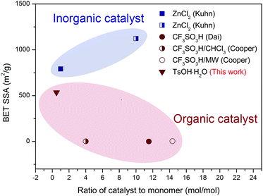 | ||
| Fig. 1 Comparison of the catalyst to monomer ratio and the BET SSA of various CTF-1s catalyzed by different catalysts (data was derived from the corresponding literature).23,28–30 | ||
In this study, p-toluenesulfonic acid monohydrate (TsOH·H2O), a solid-state organic acid with medium-strong acidity, was selected as the catalyst for the synthesis of CTF-1. The evolution of the CTF framework construction, along with the pore formation, was elucidated by chemical structure analysis and crystal parameter calculations. In addition, a method for crystallite size calculation was developed based on the deconvoluted powder X-ray diffractometer (PXRD) patterns, which shows great potential in demonstrating the relationship between the crystallite development and porosity formation.
Experimental
Chemicals
DCB was obtained from J&K Scientific Ltd. TsOH·H2O was purchased from Sinopharm Chemical Reagent Beijing Co. Ltd. All chemicals were used as received.Synthesis of the triazine-based polymer
DCB (1.28 g, 10 mmol) and TsOH·H2O (0.95 g, 5 mmol) were mixed using a mortar and transferred to a quartz ampoule (3 × 7 cm) under a nitrogen atmosphere. The ampoule was vacuumed, sealed, and heated at 250 °C for 5 h, then at 300 °C for 5 h, and finally at 350 °C for 10 h. Subsequently, the ampoule was allowed to cool down to room temperature and then opened. The as-obtained triazine-based polymer was solid and black in colour.Post-processing of the triazine-based polymer
The triazine-based polymer (0.42 g) was added to a porcelain crucible, covered with a lid, and placed inside a quartz tubular furnace. No further catalyst was added to the system during this process. Then, under a nitrogen atmosphere, the crucible was heated to either 400 °C or 500 °C, and this temperature was maintained for 20 h. Both as-obtained solid products were black in color and were designated as CTF-1@400 (prepared at 400 °C) and CTF-1@500 (prepared at 500 °C).Characterizations
Fourier transform infrared spectroscopy (FTIR) spectra were obtained using a Tensor-27 spectrometer at room temperature. X-ray photoelectron spectroscopy (XPS) measurements were performed using an ESCALAB250XI instrument. 13C-solid-state nuclear magnetic resonance (13C-solid NMR) spectra were obtained using a Bruker Avance 400 MHz spectrometer. Powder X-ray diffractograms (PXRD) were obtained in the reflection mode using a Rigaku D/max 2500 powder X-ray diffractometer with Cu-Kα radiation (λ = 1.4518 Å). Nitrogen sorption measurements were performed at 77 K using a Micromeritics ASAP 2020 surface area and porosimetry analyzer. Pyrolysis-gas chromatography/mass spectrometry (Py-GC/MS) experiments were performed using a EGA/PY-303D pyrolyser connected to a QP2010Ultra GC-MS. Finally, elemental analysis was performed using a Flash EA 1112 analyzer.Calculation of the crystallite size
PXRD patterns were baseline corrected and smoothed using the MDI Jade software, and the deconvolution of the curves was performed using the Origin software. The d-spacing (dhkl) and the crystallite dimension (Dhkl) were calculated by the following equations:The Bragg equation:
 | (1) |
The Scherrer equation:
 | (2) |
Results and discussion
Characterization of the CTF structures
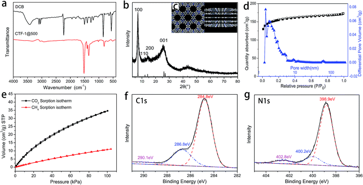
The chemical structure of CTF-1@500 was confirmed by FTIR, XPS and 13C solid NMR. In the FTIR spectrum of CTF-1@500 (Fig. 2a), the absence of the peak corresponding to the nitrile group (2230 cm−1) and the presence of clear peaks for triazine structures (1515 and 1350 cm−1) indicated the successful transformation of the nitrile groups into triazine structures via trimerization. The structure of CTF-1@500 was also confirmed by XPS. The peak with a binding energy of 286.8 eV (corresponding to triazine carbon) in the deconvoluted C 1s spectrum (Fig. 2f) and the peak at a binding energy of 398.9 eV (corresponding to triazine N 1s signal) in the N 1s spectrum (Fig. 2g) were in agreement with the FTIR results.4 In addition, the peak at 169.8 ppm in the 13C solid NMR of CTF-1@500 (Fig. S1†), attributing to the triazine structure, further verified the existence of triazine structure in CTF-1@500.The periodic chemical structure of CTF-1@500 was calculated using the Materials Studio software (Fig. 2c). The structure of the crystal cell is shown in Fig. S2,† from which the PXRD pattern is predicted and shown in Fig. 2b. Obviously, the observed PXRD signals appear at almost the same positions as the calculated value; thus, the formation of crystalline triazine-based frameworks is confirmed.
The hexagonally packed triazine-based framework would bring in large quantity of nanopores, and the pore structure of CTF-1@500 was investigated by nitrogen sorption experiments at 77 K. The type I isotherm (Fig. 2d) indicated the presence of abundant micropores, and the BET SSA was determined to be 535 m2 g−1. As illustrated in Fig. 1, using TsOH·H2O, an organic acid with medium acidity, a smaller amount of catalyst was needed and a higher BET SSA was achieved, as compared to that of CTF-1 prepared with CF3SO3H. The maximum value for the pore size as calculated by the non-local density functional theory (NL-DFT) was 15.91 Å, which was quite close to the unit cell parameter (a = b = 12.58 Å, Fig. S2†). Moreover, the adsorption capacity of CTF-1@500 for CO2 and CH4 at 298 K were measured to evaluate their potential application as gas capture and storage materials. The volumetric CO2 and CH4 sorption isotherms (Fig. 2e) show that the uptakes at 1 bar for CO2 and CH4 are 1.5 mmol g−1 and 0.50 mmol g−1, respectively. The result indicates remarkable capacity of CTF-1@500 for gas, especially for CO2. This capacity was relatively higher than that of CTF-1 prepared with ZnCl2 (ref. 4) (1.41 mmol g−1).
Evolution during pore formation
Under acidic conditions, nitriles tend to transform into triazine structures via trimerization. Polymerization of DCB catalyzed by TsOH was carried out below a relatively low temperature (350 °C) in a vacuum-sealed system. The reaction for the catalytic trimerization of DCB is shown in Scheme 1a. The protons of TsOH could facilitate the nucleophilic addition of nitrile groups; this formed the triazine-based polymer. Subsequently, during the treatment at 500 °C in an open system, the ongoing reversible trimerization reaction would benefit the growth of CTF crystals into larger and thicker lamellae to afford CTF-1@500. However, due to the existence of both steric and kinetic limitations, the final CTF solid at equilibrium consisted of a combination of crystalline and amorphous domains, as illustrated in Scheme 1b.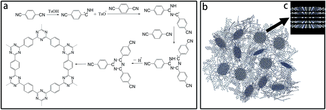 | ||
| Scheme 1 (a) Trimerization reaction for DCB catalyzed by TsOH; (b) schematic for the CTF structures; and (c) schematic for crystal CTF. | ||
To study the evolution of the framework construction, CTF-1@400 was prepared from the triazine-based polymer via a similar post treatment at 400 °C as CTF-1@500. Chemical and structural characterizations were performed on the products obtained at the first stage (triazine-based polymer) and at the second stage (CTF-1@400 and CTF-1@500) to reveal the evolution.
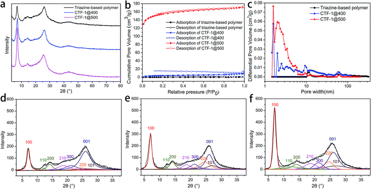
The FTIR spectra (Fig. 3a) indicated that early in the first step (polymerization), triazine structures (1515 and 1350 cm−1) are formed; after the post-treatment, CTF-1@400 and CTF-1@500 largely retain such structure. In the XPS results, the signals at 286.8 eV in the deconvoluted C 1s spectra and 398.9 eV in the deconvoluted N 1s spectra (Fig. S3†) further verify the successful formation and retention of triazine rings in triazine-based polymer, CTF-1@400 and CTF-1@500. The disappearance of the weak peak at around 1720 cm−1 in the FTIR spectra of CTF-1@400 and CTF-1@500 (Fig. 3a), along with the disappearance of the peak at 289.1 eV in the C 1s deconvoluted spectra of CTF-1@400 and CTF-1@500 (Fig. S3†), indicated the removal of carbonyl-type impurities from the triazine-based polymer during the post-treatment at high temperatures. The formation of these carbonyl-type impurities may be related to crystalliferous water (from TsOH·H2O) sealed and trapped within the system during the first step, where hydrolysis of the nitrile groups may be triggered. Later in the second step, the high-temperature treatment of the materials in an open system facilitates the decomposition and removal of the impurities. In addition, the appearance of a new peak at 290.5 eV (related to π-carbon) in the C 1s spectrum of CTF-1@500 (Fig. S3j†) reveals the improvement of the triazine structure in larger scales. It is worth mentioning that for CTF-1@500, the peaks attributed to the nitrile groups were still detected by XPS (400.2 eV in N 1s, Fig. S3k†) and 13C-solid NMR spectrum (116 ppm, Fig. S1†), which may be related to the dynamically reversible trimerization of nitriles;34 the catalyst plays a vital role in this process. The retention of peaks centered at 168.7 eV in the deconvoluted S 2p spectra (corresponding to sulfonate structure, as shown in Fig. S3†) indicates the survival of sulfonate group at high temperatures. Table 1 shows the elemental analysis of triazine-based polymer, CTF-1@400, and CTF-1@500. It can be seen that CTF-1@500 has the C, N, and H content that is closest to the theoretical value. CTF-1@500 also has the lowest O amount, suggesting the purification of the framework by the release of oxygen-containing impurities. The similar S content in the triazine-based polymer, CTF-1@400, and CTF-1@500 indicates that the catalyst remains in the system throughout the whole process. On the other hand, the clear difference between the theoretical and experimental N content of CTF-1@500 may be attributed to the presence of residual catalyst. It has been speculated that the retention of the sulfonate structure may play a critical role in the rearrangement and development of the crystalline structure by allowing the subsequent reversible trimerization. The catalytic mechanism of the sulfonate structure will be studied in depth in our subsequent works.
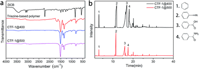 | ||
| Fig. 3 (a) FTIR spectra of DCB, the triazine-based polymer, CTF-1@400 and CTF-1@500; (b) pyrogram with the fragments generated from the triazine-based polymer at 400 °C and 500 °C. | ||
| Sample | C | N | H | S | O | C/N (mol) | C/H (mol) | |
|---|---|---|---|---|---|---|---|---|
| Theoretical | — | 75 | 21.875 | 3.125 | — | — | 4 | 2 |
| Experimental | Triazine-based polymer | 69.04 | 15.72 | 3.22 | 3.69 | 8.33 | 5.12 | 1.79 |
| CTF-1@400 | 71.36 | 16.32 | 2.89 | 3.96 | 5.47 | 5.1 | 2.06 | |
| CTF-1@500 | 73.99 | 16.37 | 2.92 | 3.82 | 2.9 | 5.27 | 2.11 |
Py-GC/MS experiments of the triazine-based polymer were performed at 400 and 500 °C (Fig. 3b) to study the gas evolution during the reversible trimerization reaction at high temperatures. The pyrogram fragments of benzene, cyanobenzene, benzoic acid, and benzamide confirm the decomposition and removal of the carbonyl-type impurities, as predicted from the FTIR spectra shown in Fig. 3a. Fortunately, no triazine-related fragments were found.
The abovementioned chemical characterizations revealed that as the reaction temperature increases, the orderness of framework structure is improved. PXRD was performed on the products of the two stages to reveal the trend in the crystallinity, and the patterns are shown in Fig. 4a. It can be seen that all products obtained after the two stages were partially crystalline materials, where the crystallites were distributed in a mass of amorphous triazine-based framework, as in the structure shown in Scheme 1b. The ever-strengthening diffraction peaks, especially the (100) and (001) peaks, suggested the development of lamellae with an improved stacking. The patterns were baseline corrected, smoothed, and fitted to elucidate the parameters for each crystal face, and the deconvoluted patterns are shown in Fig. 4d–f.36–38 The (100) and (001) crystal faces, representing the CTF lamellae and the stacking of lamellae, respectively, were selected for the calculation. Moreover, the d-spacing (dhkl) and the crystallite dimension (Dhkl) values are listed in Table 2.
| (100) crystal face | (001) crystal face | |||||||
|---|---|---|---|---|---|---|---|---|
| 2θ100 (°) | d100 (Å) | β (°) | D100 (Å) | 2θ001 (°) | d001 (Å) | β (°) | D001 (Å) | |
| a Based on experimental PXRD values.b Theoretical values as calculated with the Materials Studio software.c Calculated based on the experimental θ100 value.d Calculated based on the theoretical d001 value. | ||||||||
| Theoretical | 7.05 | 12.53b | — | — | 26.05 | 3.42b | — | — |
| Triazine-based polymer | 6.92a | 12.77c | 1.11c | 71c | 26.05d | 3.42b | 4.47d | 18d |
| CTF-1@400 | 6.99a | 12.65c | 1.02c | 77c | 26.05d | 3.42b | 3.37d | 24d |
| CTF-1@500 | 7.00a | 12.63c | 0.73c | 107c | 26.05d | 3.42b | 4.02d | 20d |
During the post-treatment stage, at higher temperatures, d100 is closer to the theoretical value, suggesting the development of the lamellae. Based on the d100 value, which indicates the pore size of the framework, CTF-1@500 possesses a very pore size similar to the theoretical value. The significant increase in the D100 value after treatment at 500 °C implies the evident development of the lamellae. However, the D001 value exhibits a different trend, in which the maximum value is obtained for CTF-1@400.
The superior porosity was linked to the periodic packing of the CTF structures. Nitrogen sorption experiments at 77 K were also performed on the triazine-based polymer and CTF-1@400. Compared with CTF-1@500, the triazine-based polymer and CTF-1@400 possessed a small pore volume (Fig. 4c) and the SSAs were only 5 and 16 m2 g−1, respectively. The improvement of the lamellae and their ordered packing was not accomplished before the treatment at 500 °C; thus, the intrinsic micropores enclosed by the frameworks are limited. On the other hand, for CTF-1@500, although the majority of the pores had a size within 2 nm, there were also some mesopores with a size between 2 and 6 nm, which may result from the partial decomposition of the framework. This decomposition may occur at the outer layers of the crystallites, thus resulting in a decreased D001.
Conclusions
CTF-1 was prepared by a two-step route, where TsOH·H2O, an organic acid with medium acidity, was used as the catalyst to trigger the trimerization of DCB. Compared with the analogous framework prepared with a strong Brønsted acid such as CF3SO3H, CTF-1@500 prepared in this work exhibited a higher BET SSA; remarkably, this was achieved with a lower catalyst dosage. In addition, we could anticipate an enhanced performance of the CTF by incorporating more suitable monomers into our future TsOH·H2O-catalyzed routes.Moreover, the evolution of the framework was studied by characterization of the chemical structure and calculation of the crystal parameters during different stages of the preparation. The results showed that the formation of the triazine-based polymer is accomplished in the presence of TsOH·H2O at relatively low temperatures. In addition, the low crystallinity and porosity of the triazine-based polymer may be attributed to the presence of impurities in its structure and to a limited crystallite ordering. However, when treated at relatively high temperatures, the growth of the crystallites leads to a remarkable increase in the porosity. Finally, the method proposed in this study for evaluating the CTF crystallite size may provide a better understanding of the formation of CTFs.
Conflicts of interest
There are no conflicts to declare.Acknowledgements
The authors would like to acknowledge Dr Yuanping Yi (Institute of the Chemistry Chinese Academy of Science) for supporting the simulations and calculations with the Materials Studio software. The authors also gratefully acknowledge the financial support of the National Natural Science Foundation of China (No. 51403218 & No. 51473171 & No. 21604090). The authors gratefully thank the Young Elite Scientist Sponsorship Program by CAST (YESS) and the Youth Innovation Promotion Association of CAS (No. 2017047).Notes and references
- A. Taguchi and F. Schüth, Microporous Mesoporous Mater., 2005, 77, 1–45 CrossRef CAS.
- M. Hartmann, Chem. Mater., 2005, 17, 4577–4593 CrossRef CAS.
- M. E. Davis, Nature, 2002, 417, 813–821 CrossRef CAS PubMed.
- Y. Zhao, K. X. Yao, B. Teng, T. Zhang and Y. Han, Energy Environ. Sci., 2013, 6, 3684 CAS.
- S. Hug, M. B. Mesch, H. Oh, N. Popp, M. Hirscher, J. Senker and B. V. Lotsch, J. Mater. Chem. A, 2014, 2, 5928–5936 CAS.
- H. Liao, H. Ding, B. Li, X. Ai and C. Wang, J. Mater. Chem. A, 2014, 2, 8854 CAS.
- J. Lee, O. K. Farha, J. Roberts, K. A. Scheidt, S. T. Nguyen and J. T. Hupp, Chem. Soc. Rev., 2009, 38, 1450–1459 RSC.
- J. R. Li, R. J. Kuppler and H. C. Zhou, Chem. Soc. Rev., 2009, 38, 1477–1504 RSC.
- A. I. Cooper, CrystEngComm, 2013, 15, 1483 RSC.
- B. P. Biswal, S. Kandambeth, S. Chandra, D. B. Shinde, S. Bera, S. Karak, B. Garai, U. K. Kharul and R. Banerjee, J. Mater. Chem. A, 2015, 3, 23664–23669 CAS.
- L. Bai, Q. Gao and Y. Zhao, J. Mater. Chem. A, 2016, 4, 14106–14110 CAS.
- P. Puthiaraj, Y.-R. Lee, S. Zhang and W.-S. Ahn, J. Mater. Chem. A, 2016, 4, 16288–16311 CAS.
- R. K. Yadav, A. Kumar, N.-J. Park, K.-J. Kong and J.-O. Baeg, J. Mater. Chem. A, 2016, 4, 9413–9418 CAS.
- X. Ding, L. Chen, Y. Honsho, X. Feng, O. Saengsawang, J. Guo, A. Saeki, S. Seki, S. Irle, S. Nagase, V. Parasuk and D. Jiang, J. Am. Chem. Soc., 2011, 133, 14510–14513 CrossRef CAS PubMed.
- Q. Fang, J. Wang, S. Gu, R. B. Kaspar, Z. Zhuang, J. Zheng, H. Guo, S. Qiu and Y. Yan, J. Am. Chem. Soc., 2015, 137, 8352–8355 CrossRef CAS PubMed.
- S. Dalapati, E. Jin, M. Addicoat, T. Heine and D. Jiang, J. Am. Chem. Soc., 2016, 138, 5797–5800 CrossRef CAS PubMed.
- L. Stegbauer, K. Schwinghammer and B. V. Lotsch, Chem. Sci., 2014, 5, 2789–2793 RSC.
- S. Lin, C. S. Diercks, Y. B. Zhang, N. Kornienko, E. M. Nichols, Y. Zhao, A. R. Paris, D. Kim, P. Yang, O. M. Yaghi and C. J. Chang, Science, 2015, 349, 1208–1213 CrossRef CAS PubMed.
- H. Xu, J. Gao and D. Jiang, Nat. Chem., 2015, 7, 905–912 CrossRef CAS PubMed.
- H. Xu, S. Tao and D. Jiang, Nat. Mater., 2016, 15, 722–726 CrossRef CAS PubMed.
- A. P. Cote, A. I. Benin, N. W. Ockwig, M. O'Keeffe, A. J. Matzger and O. M. Yaghi, Science, 2005, 310, 1166–1170 CrossRef CAS PubMed.
- S. Y. Ding and W. Wang, Chem. Soc. Rev., 2013, 42, 548–568 RSC.
- P. Kuhn, M. Antonietti and A. Thomas, Angew. Chem., Int. Ed. Engl., 2008, 47, 3450–3453 CrossRef CAS PubMed.
- J. Liu, E. Zong, H. Fu, S. Zheng, Z. Xu and D. Zhu, J. Colloid Interface Sci., 2012, 372, 99–107 CrossRef CAS PubMed.
- A. Bhunia, I. Boldog, A. Möller and C. Janiak, J. Mater. Chem. A, 2013, 1, 14990 CAS.
- F. Chang, J. Guo, G. Wu, L. Liu, M. Zhang, T. He, P. Wang, P. Yu and P. Chen, RSC Adv., 2015, 5, 3605–3610 RSC.
- W. Suksaengrat and P. Srepusharawoot, Microelectron. Eng., 2013, 108, 192–194 CrossRef CAS.
- P. Katekomol, J. Roeser, M. Bojdys, J. Weber and A. Thomas, Chem. Mater., 2013, 25, 1542–1548 CrossRef CAS.
- J. Liu, Y. Hu and J. Cao, Catal. Commun., 2015, 66, 91–94 CrossRef CAS.
- P. Kuhn, A. Thomas and M. Antonietti, Macromolecules, 2009, 42, 319–326 CrossRef CAS.
- P. Kuhn, A. Forget, D. Su, A. Thomas and M. Antonietti, J. Am. Chem. Soc., 2008, 130, 13333–13337 CrossRef CAS PubMed.
- X. Zhu, C. Tian, S. M. Mahurin, S. H. Chai, C. Wang, S. Brown, G. M. Veith, H. Luo, H. Liu and S. Dai, J. Am. Chem. Soc., 2012, 134, 10478–10484 CrossRef CAS PubMed.
- C. Reece, D. J. Willock and A. Trewin, Phys. Chem. Chem. Phys., 2015, 17, 817–823 RSC.
- S. Ren, M. J. Bojdys, R. Dawson, A. Laybourn, Y. Z. Khimyak, D. J. Adams and A. I. Cooper, Adv. Mater., 2012, 24, 2357–2361 CrossRef CAS PubMed.
- J. I. Langford and A. J. C. Wilson, J. Appl. Crystallogr., 1978, 11, 102–113 CrossRef CAS.
- J. M. Jiménez Mateos, E. Romero and C. G. De Salazar, Carbon, 1993, 31, 1159–1178 CrossRef.
- H. H. Chang, L. K. Chang, C. D. Yang, D. J. Lin and L. P. Cheng, J. Membr. Sci., 2016, 513, 186–196 CrossRef CAS.
- R. M. Mohanty, K. Balasubramanian and S. K. Seshadri, J. Alloys Compd., 2007, 441, 85–93 CrossRef CAS.
Footnote |
| † Electronic supplementary information (ESI) available. See DOI: 10.1039/c7ra07181g |
| This journal is © The Royal Society of Chemistry 2017 |

