DOI:
10.1039/C7RA05744J
(Paper)
RSC Adv., 2017,
7, 36473-36481
Flexible composite film of aligned polyaniline grown on the surface of magnetic barium titanate/polyvinylidene fluoride for exceptional microwave absorption performance†
Received
22nd May 2017
, Accepted 12th July 2017
First published on 24th July 2017
Abstract
A rational structure design is always an attractive approach for high-performance microwave absorbers. Accordingly, flexible BaTiO3@Ni–P/polyvinylidene fluoride/polyaniline (BaTiO3@Ni–P/PVDF/PANI) composite films were fabricated by growing aligned PANI on the surface of a BaTiO3@Ni–P/PVDF composite film. Morphology and structure characterization showed that uniform core–shell BaTiO3@Ni–P microspheres and the unique conelike shapes of aligned PANI were innovatively fabricated. The effect of the special structure on microwave absorption properties was investigated within the 2–18 GHz frequency range. The prepared absorbents displayed exceptional microwave absorption performances. The minimum reflection of BaTiO3@Ni–P/PVDF/PANI reached −22.56 dB at 12.72 GHz with a thickness of 2 mm, and the bandwidth that corresponded to reflection loss below −10 dB reached 4.33 GHz (11.12–15.45 GHz). The possible absorption mechanism of BaTiO3@Ni–P/PVDF/PANI was also studied in detail. Results offer an effective means to develop microwave absorbers via rational microstructure design.
1. Introduction
Electromagnetic wave (EW) irradiation is an uncontrolled offshoot of the explosive growth of information technology and the widespread use of high-frequency electromagnetic microwaves.1,2 EW irradiation not only influences the operation of electronic devices but also endangers human health.3,4 Extensive studies have focused on the development of high-performance microwave absorption materials (MAMs) to solve the EW pollution problem. Interest in ferromagnetic materials,5,6 C materials,7–9 and conducting polymers10,11 has increased recently.
As a typical dielectric material, barium titanate (BaTiO3) has attracted considerable scientific attention due to its remarkable properties, including high dielectric constant, spontaneous polarization, easy preparation and low cost.12,13 In particular, BaTiO3 has received extensive attention as an electromagnetic wave absorber given its tremendous dielectric relaxation in the gigahertz frequency bands. Nevertheless, the microwave absorption property of pure BaTiO3 is relatively poor because of its non-magnetic feature.14 Therefore, magnetic functionalized BaTiO3 materials that combine dielectric and magnetic losses have attracted considerable attention and have been extensively studied to improve their microwave absorption performance.15,16 Wang et al. fabricated BaTiO3/Ni hybrid particles with a minimum reflection loss (RL) of −14.9 dB at 13.6 GHz, and a frequency bandwidth of <−5 dB over nearly the entire Ku-band with a thickness of 1.2 mm.17 Qing et al. prepared BaTiO3/carbonyl iron composites with a minimum RL of −42 dB at 4.1 GHz and a thickness of 2 mm.18 Yang et al. found that the permittivity and permeability of BaTiO3/carbonyl iron composites can be tuned by the mass ratio of the components to improve absorption properties. The optimal RL of BaTiO3/carbonyl iron composites reached −24 dB at around 3.2 GHz.19 The aforementioned studies show that the complex relative permittivity and permeability of magnetic-functionalized BaTiO3 can be balanced by its complex loss mechanism to improve microwave absorption properties.
Polyaniline (PANI), which was used as a microwave absorption material in previous works, has always been a popular topic because of its advantages of environmental stability and tunable conductivity.20–23 PANI-based composites, such as graphene@Fe3O4@SiO2@PANI,24 PANI/BaFe12O19/Y3Fe5O12,25 Co/C/PANI,26 and graphene foam/PANI,27 exhibit enhanced microwave absorption properties. To our knowledge, reports regarding aligned PANI composites applied to EW absorbers remain rare.
The cooperative actions of dielectric, magnetic, resistance losses and the novel structure are the key factors that determine the microwave absorption properties of absorbers.28–31 In consideration of the aforementioned situation, we used a multi-phase structure that involved Ni–P-covered BaTiO3 combined with aligned PANI to design flexible polyvinylidene fluoride (PVDF)-based composites. In this study, BaTiO3@Ni–P/PVDF/PANI composites were prepared using Ni–P-covered BaTiO3 compound with PVDF via electroless deposition technology and physical mixing. Then, aligned PANI was grown on the surface of the composites via dilute polymerization. The multi-phase structure of the BaTiO3@Ni–P/PVDF/PANI composites can induce different ways to produce loses, and the unique cone-like shape of aligned PANI can form dissipation micro-current and long transmission paths to enhance EW energy absorption. In consideration of these views, our findings are promising for microwave absorption materials.
2. Experimental section
2.1 Materials
BaTiO3 (diameter, ≤100 nm), N,N-dimethyl formamide (DMF, 99.5%), aniline (99.5%), ammonium persulfate (APS, 98.0%), perchloric acid (HClO4, 70%), SnCl2 (99.0%), PbCl2 (≥99.9%), NiSO4·6H2O (98.5%), Na3C6H5O7·2H2O (≥99.0%), H3BO3 (99.8%) and NaH2PO2·H2O (≥99.0%) were purchased from Aladdin Industrial Corporation. PVDF was purchased from Shanghai 3F Company.
2.2 Preparation of BaTiO3@Ni–P core–shell structure
BaTiO3 (1.0 g) was sensitized in SnCl2 (0.08 M) solution for 5 min and then activated in PdCl2 (0.01 M) solution for 5 min before performing electroless deposition. Subsequently, the pretreated BaTiO3 powder was immersed in an electroless deposition solution (pH = 9 and temperature controlled under 25 °C) with constant stirring for 1 h. The components of the electroless deposition solution are listed in Table 1. The BaTiO3@Ni–P powder was obtained by filtering and washing with deionized water. The reaction equation can be described by eqn (1)–(4). The mechanisms of the pretreatment and electroless deposition processes are schematically illustrated in Fig. 1a.| | |
SnCl2 + PdCl2 → SnCl4 + Pd
| (1) |
| | |
Ni2+ + H2PO2− + H2O → Ni + 2H+ + H(HPO3)−
| (2) |
| | |
2HPO2− + 2H2O → 2H(HPO3)− + H2
| (3) |
| | |
H2PO2− + 2H+ + e− → 2H2O + P
| (4) |
Table 1 The components of the electroless deposition solution
| Nickel resource |
Complexing agent |
Buffer agent |
Reducing agent |
| NiSO4·6H2O (25 g L−1) |
Na3C6H5O7·2H2O (35 g L−1) |
H3BO3 (15 g L−1) |
NaH2PO2·H2O (30 g L−1) |
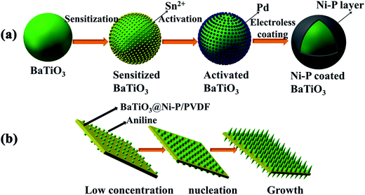 |
| | Fig. 1 Schematic illustration of (a) formation of Ni–P-coated BaTiO3 and (b) formation of aligned PANI on the surface of the composites. | |
2.3 Preparation of BaTiO3@Ni–P/PVDF composite
PVDF powder was dissolved in DMF solution with a mass ratio of 1![[thin space (1/6-em)]](https://www.rsc.org/images/entities/char_2009.gif) :9 under constant stirring at room temperature for 24 h. Afterward, BaTiO3@Ni–P (70 wt% loaded onto PVDF) was added by stirring into the solution to obtain a uniformly mixed solution. The mixture was then poured into a glass plate and dried in a vacuum oven at 40 °C for 12 h. Then, the BaTiO3@Ni–P/PVDF film was obtained. Moreover, the pure PVDF film and the BaTiO3/PVDF film were prepared in the same manner.
:9 under constant stirring at room temperature for 24 h. Afterward, BaTiO3@Ni–P (70 wt% loaded onto PVDF) was added by stirring into the solution to obtain a uniformly mixed solution. The mixture was then poured into a glass plate and dried in a vacuum oven at 40 °C for 12 h. Then, the BaTiO3@Ni–P/PVDF film was obtained. Moreover, the pure PVDF film and the BaTiO3/PVDF film were prepared in the same manner.
2.4 Preparation of BaTiO3@Ni–P/PVDF/PANI composite
Aligned PANI was grown on the surface of the BaTiO3@Ni–P/PVDF film through a dilute polymerization process (Fig. 1b). In a typical process, 0.01 M aniline was added to the HClO4 (1 M) solution under constant stirring until a homogenous suspension was achieved. Subsequently, the BaTiO3@Ni–P/PVDF film was introduced into the mixture solution, and then APS aqueous solution ([aniline]/[APS] = 1.5) was added to the suspension. The polymerization process was performed in an ice bath for 12 h under constant stirring.
2.5 Characterization
The morphology of the samples was observed using a field emission scanning electron microscope (Hitachi S-4800) and transmission electron microscope (JEOL JEM-2100F). The crystal structure of the prepared powders was analyzed with an X-ray diffractometer (Bruker AXS, D8-Discover) using Cu Kα radiation. Fourier transform infrared spectroscopy (FT-IR) was performed using a Nicolet 5700 spectrometer (Thermo Electron Corporation, USA). X-ray photoelectron spectroscopy (XPS) was performed using a K-alpha + photoelectron spectrometer (Thermo Fisher Scientific) to measure the chemical composition and chemical states of the samples. The magnetic properties of the sample in powder form were determined using a model VersaLab vibrating sample magnetometer (VSM, Quantum Design). The composite films (70 wt% BaTiO3 or BaTiO3@Ni–P powder loaded onto PVDF) used for electromagnetic measurements were prepared via a simple hot-molding procedure. The films were collapsed and compressed into wafers for 3 min at 200 °C under 5 MPa, and toroidally shaped samples (φout = 7 mm, φinner = 3.04 mm) were obtained. The coaxial circle sample (BaTiO3@Ni–P/PVDF/PANI) was obtained by growing the aligned PANI on the surface of the coaxial circles of BaTiO3@Ni–P/PVDF. The effective complex permittivity εr (εr = ε′ − jε′′) and permeability μr (μr = μ′ − jμ′′) were measured with a vector network analyzer (N5224A, Agilent) within the 2–18 GHz range.
3. Results and discussion
3.1 Morphology and structure of BaTiO3@Ni–P
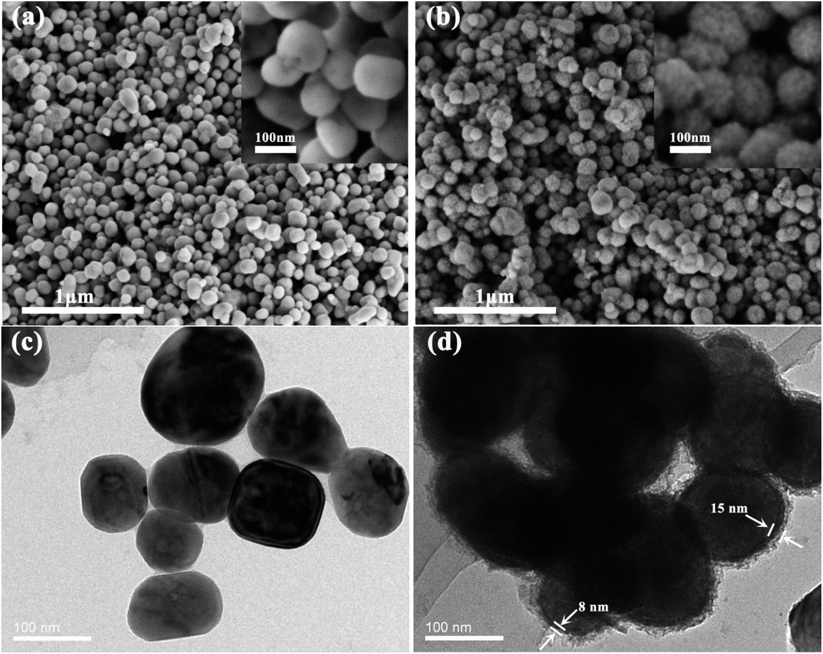
The scanning electron microscopy (SEM) morphologies of pristine BaTiO3 and BaTiO3@Ni–P are shown in Fig. 2. As shown in Fig. 2a, pristine BaTiO3 has a smooth surface with a diameter of approximately 100 nm, whereas the Ni–P-covered BaTiO3 has a rough surface (Fig. 2b). The insets of Fig. 2a and b show that Ni–P particles adhered uniformly onto the surface of BaTiO3. The elemental composition of BaTiO3@Ni–P was evaluated using energy-dispersive X-ray spectroscopy (EDS), and the results are shown in Fig. S1.† The presence of O, Ti, Ba, Ni and P elements in BaTiO3@Ni–P particles was observed. The atomic ratios of the electrolessly deposited Ni and P reached 10.41% and 2.27%, respectively.
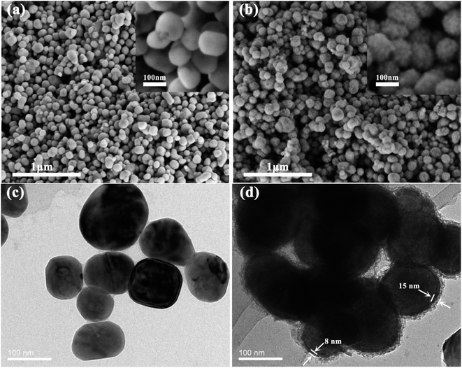 |
| | Fig. 2 SEM images of (a) pristine BaTiO3 and (b) BaTiO3@Ni–P. TEM images of (c) pristine BaTiO3 and (d) BaTiO3@Ni–P. | |
Fig. 2c and d show the transmission electron microscopy (TEM) images of BaTiO3 and BaTiO3@Ni–P, respectively. Compared with pure BaTiO3 (Fig. 2c), the Ni–P coated onto the surface of BaTiO3 and the core–shell structure were further confirmed (Fig. 2d). As shown in Fig. 2d, the Ni–P layer comprises dense and loose layers. The difference in compact degree can be attributed to the different catalytic activity centers, which are the absorbed Pd and autocatalytic Ni.
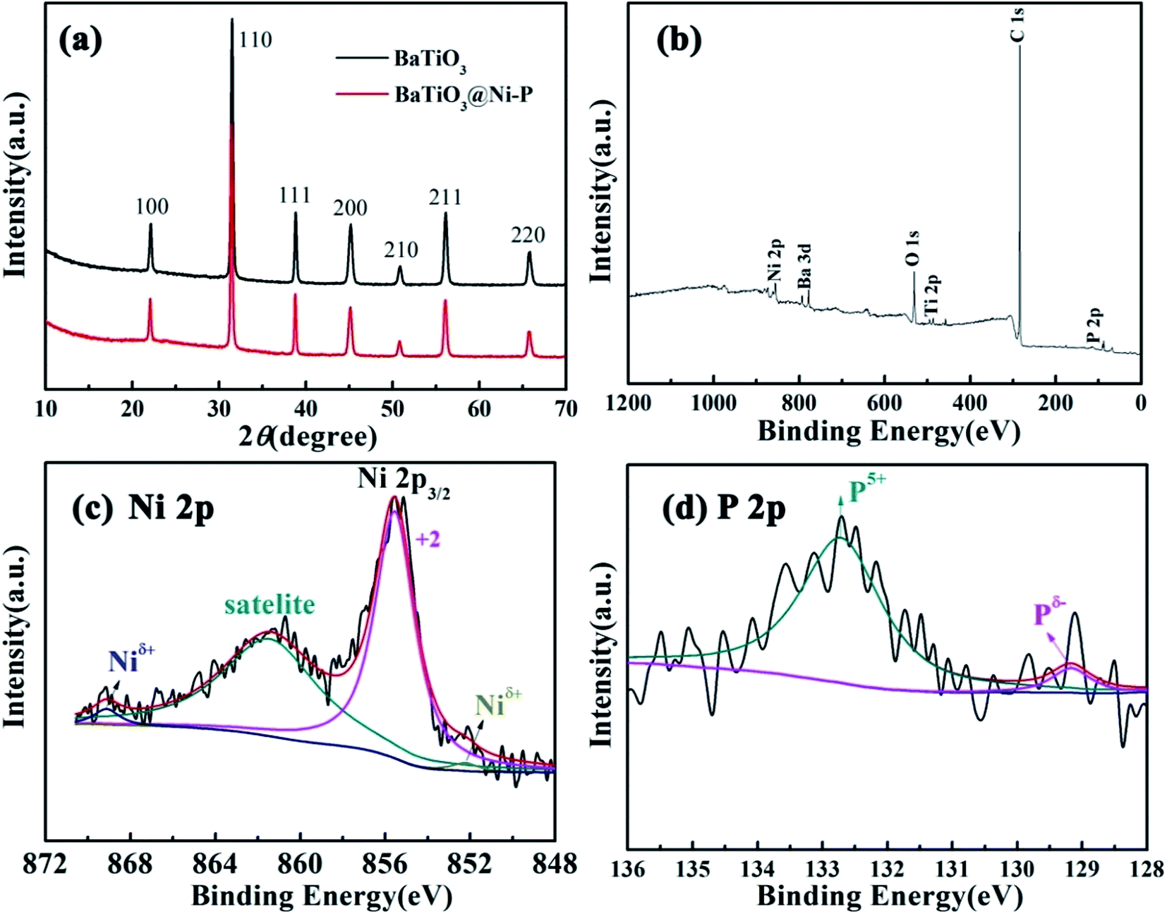
X-ray diffraction (XRD) measurement was performed to investigate the crystal phase structure of the as-prepared BaTiO3@Ni–P. As shown in Fig. 3a, the diffraction peaks located at 2θ = 22.1°, 31.5°, 38.8°, 45.2°, 50.9°, 56.1° and 65.8° can be indexed to the (100), (110), (111), (200), (210), (211), and (220) planes of BaTiO3, respectively (JCPDS card no. 31-0174).32 Nonetheless, no diffraction peak is assigned to Ni–P, which implies that the Ni–P layer is amorphous. XPS was performed to further understand the oxidation state of the amorphous Ni–P layer, and the corresponding results are presented in Fig. 3b–d. The survey spectrum (Fig. 3b) indicates the presence of Ba, Ti, O, Ni, P, and C from the reference, which is consistent with the result of the EDS analysis. The Ni 2p emission spectrum (Fig. 3c) is the best fitted characteristics of Ni2+, the shakeup satellite, and Niδ+ in the Ni–P compound. The peak at 855.6 eV is indexed to Ni2+ in nickel oxide. The shakeup satellite at 861.4 eV can be clearly observed at the high binding energy side of the Ni 2p3/2 edge. Two peaks, i.e., those at 852.2 eV and 869.1 eV, are assigned to Niδ+ in the Ni–P compound.33–35 In the P 2p spectra (Fig. 3d), the peak located at 129.2 eV is attributed to the reduced phosphide (denoted as Pδ−). The broad peak at 132.7 eV is assigned to oxidized P (denoted as P5+).35,36 All the aforementioned results suggest that the as-prepared BaTiO3@Ni–P consists of the Ni–P form. To identify the magnetic properties of Ni–P, VSM was used at room temperature. The result shows the saturated magnetization (Ms) of BaTiO3@Ni–P is 1.61 emu g−1 (Fig. S2†).
 |
| | Fig. 3 (a) XRD patterns of the samples. XPS survey spectra of (b) wide scan, peak deconvolution of (c) Ni 2p and (d) P 2p for BaTiO3@Ni–P. | |
3.2 Morphology and structure of BaTiO3@Ni–P/PVDF/PANI
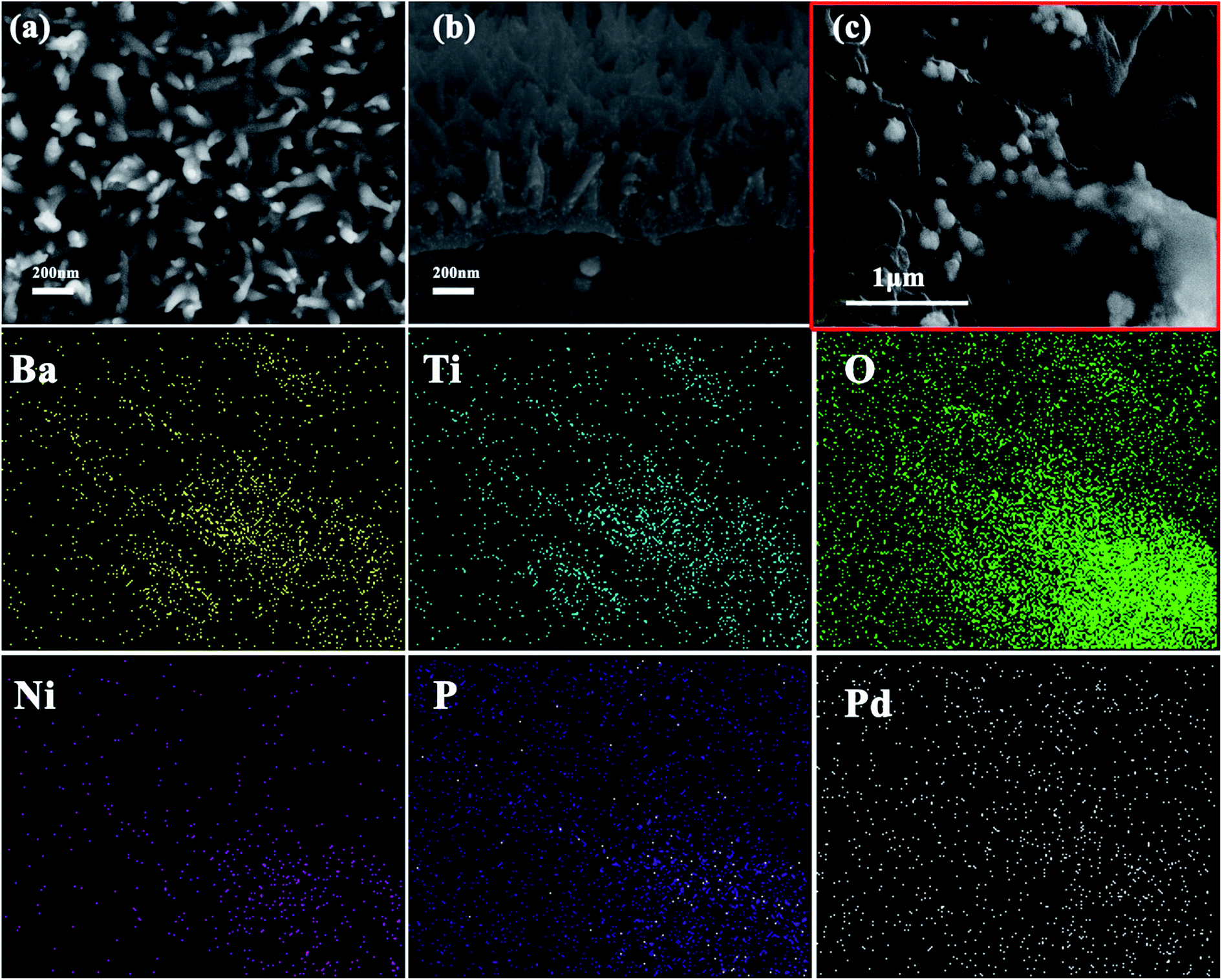
The morphology of the as-prepared BaTiO3@Ni–P/PVDF/PANI is shown in Fig. 4. The surface image (Fig. 4a) and the edge of the cross-sectional image (Fig. 4b) show that vertically aligned PANI with a length of approximately 200 nm grew on the surface of the PVDF film. The formation process of the aligned PANI is illustrated in Fig. 1b. First, active nucleation sites were generated on the surface of the films. Then, the heterogeneous nucleation of PANI occurred due to the low concentration of aniline during oxidation polymerization. Finally, PANI would further grow along the initial nuclei to form the aligned PANI on the film.37 An aligned nanostructure is a well-known cause of multiple reflections of incident EW, and a high amount of EW energy can be converted into thermal energy or other forms of energy. Therefore, such aligned nanostructure can enhance the efficiency of wave absorption and improve microwave absorption properties. The middle of the cross-sectional image (Fig. 4c) and the corresponding elemental mapping further verify that Ba, Ti, O, Ni, P and Pd elements are distributed in the BaTiO3@Ni–P/PVDF/PANI film. In addition, the crystalline phase and the chemical structure of the aligned PANI were analyzed via XRD and FT-IR, respectively (Fig. S3†). Interestingly, the PVDF-based composite absorbers exhibit flexible properties (Fig. S4†). Therefore, the BaTiO3@Ni–P/PVDF/PANI film is anticipated to have potential practical applications.
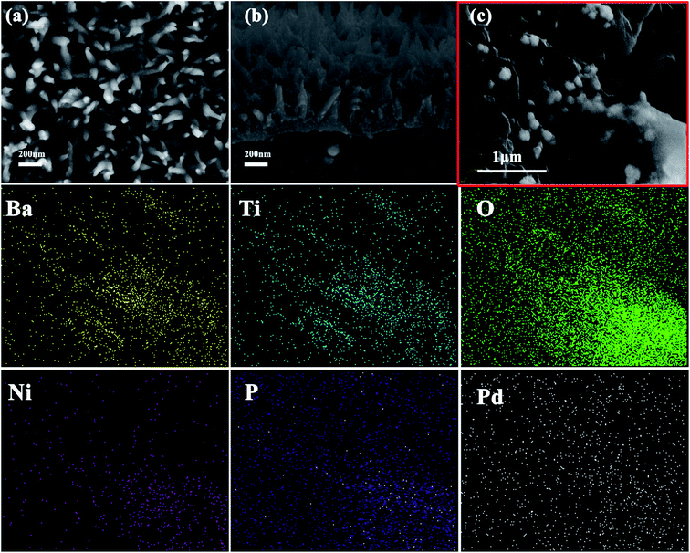 |
| | Fig. 4 SEM images of BaTiO3@Ni–P/PVDF/PANI: (a) surface image; (b) edge of the cross-sectional image; (c) middle of the cross-sectional image; and SEM–EDS elemental mappings that correspond to (c): Ba, Ti, O, Ni, P and Pd elements. | |
3.3 EW absorption properties of composites
The microwave absorption performance of an absorber is well-known to be highly associated with its effective complex permittivity (εr = ε′ − jε′′) and effective complex permeability (μr = μ′ − jμ′′). The real parts of complex permittivity and permeability represent the storage capability of EW energy, whereas the imaginary parts of effective complex permittivity and permeability represent the loss capability of EW energy.38 Fig. 5a and b show the real part (ε′) and imaginary part (ε′′) of the effective complex permittivity of the PVDF-based composites within the 2–18 GHz frequency range. The ε′ and ε′′ values of pure PVDF are within the ranges of 2–3 and 0.2–0.5, respectively, which are relatively higher than that for the epoxy resin matrix.39 Compared with those of BaTiO3/PVDF, the ε′ and ε′′ values of BaTiO3@Ni–P/PVDF are increased over the majority of the 2–18 GHz range. This result indicates that introducing Ni–P can enhance the dielectric constant of BaTiO3/PVDF, thereby reflecting increased storage and loss capabilities. However, the ε′ value of BaTiO3@Ni–P/PVDF/PANI mostly declines with the growth of aligned PANI. Notably, the ε′′ value of BaTiO3@Ni–P/PVDF/PANI exhibits a strong peak within the 7–11 GHz range, which arises from the resonance behavior.
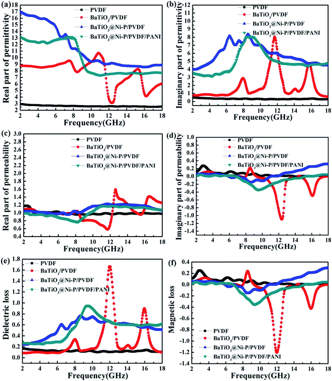 |
| | Fig. 5 Complex permittivity of samples: (a) real part and (b) imaginary part. Complex permeability of samples: (c) real part, (d) imaginary part, (e) dielectric loss, and (f) magnetic loss of samples. | |
Fig. 5c and d show the real part (μ′) and imaginary part (μ′′) of the effective complex permeability of the composites, respectively. For BaTiO3/PVDF, the μ′ and μ′′ values are within the range of 0.58–1.59 and −1.10–0.22, respectively. When BaTiO3 was coated with a Ni–P shell, the μ′ value is increased in the regions of 8.4–12.3 GHz and 14.1–16.0 GHz. Moreover, the μ′′ value is improved significantly in the region of 11.9–18 GHz. The magnetic properties of Ni–P cause this phenomenon, which effectively compensates for the low complex relative permeability of dielectric materials.
Fig. 5e and f show the dielectric loss (tanδE = ε′′/ε′) and magnetic loss (tanδμ = μ′′/μ′) of the samples. The dielectric losses of BaTiO3@Ni–P/PVDF and BaTiO3@Ni–P/PVDF/PANI fluctuate between 0.23–0.75 and 0.27–0.95, respectively, which are higher than that for BaTiO3/PVDF (i.e., within the ranges of 2–11.3, 12.6–15.5 and 16.3–18 GHz). The magnetic loss of BaTiO3@Ni–P/PVDF is higher than those of the other samples within the range of 12–18 GHz and the maximum value reached 0.29. For a magnetic material, magnetic loss is mainly caused by natural resonance and eddy current loss.39 Eddy current loss can be explained by the values of μ′′(μ′)−2f−1, which remain constant at various frequencies. By contrast, the fluctuation values indicate that the eddy current effect has an insignificant effect on magnetic loss (as shown in Fig. S5†). Therefore, magnetic loss is mainly attributed to natural resonance.
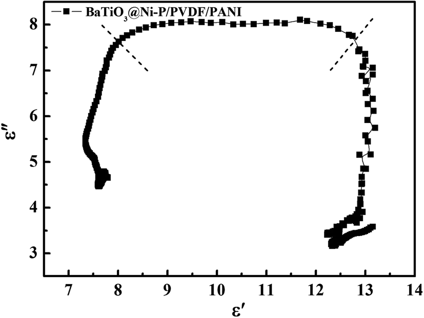
The ε′–ε′′ curves shown in Fig. 6 and S6† illustrate the dielectric loss capability of the samples. Debye dipolar relaxation theory states that each Cole–Cole semicircle corresponds to one Debye relaxation process. For BaTiO3@Ni–P/PVDF/PANI, two evident Cole–Cole semicircles are found, thereby indicating the existence of a relaxation process. Meanwhile, several semicircles in PVDF, BaTiO3/PVDF and BaTiO3@Ni–P/PVDF (Fig. S6†) imply that multi-relaxation occurs in the PVDF composites and plays a vital role in EW absorption.
 |
| | Fig. 6 ε′–ε′′ curve of BaTiO3@Ni–P/PVDF/PANI. | |
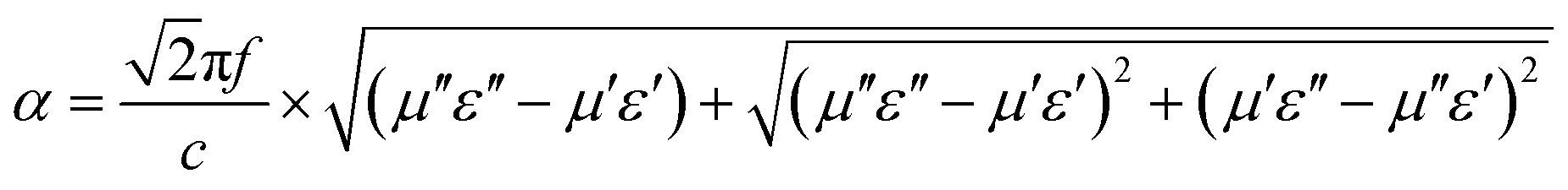
To further clarify the difference in microwave absorption properties, the attenuation constant α and impedance matching properties should also be considered apart from the electromagnetic parameters. The attenuation constant α represents the capability for dielectric and magnetic losses, which are calculated using eqn (5) as follows:40
| |
 | (5) |
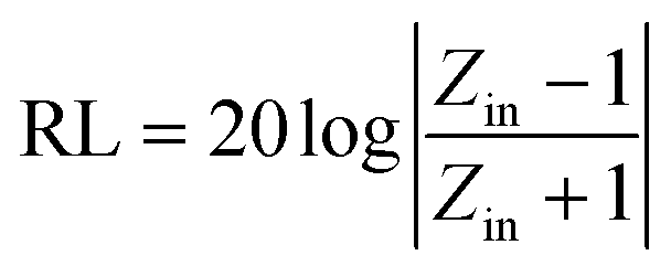
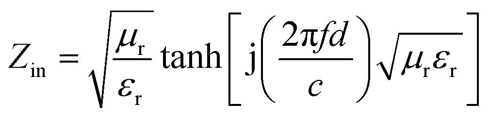
As shown in Fig. 7a, the attenuation constant α value of BaTiO3@Ni–P/PVDF has increased distinctly within the frequency ranges of 2–11.3, 12.7–15.3, and 16.6–18 GHz compared with that of BaTiO3/PVDF. In addition, the BaTiO3@Ni–P/PVDF/PANI sample clearly exhibits a higher attention constant α than that of BaTiO3@Ni–P/PVDF within the frequency range of 8.8–18 GHz. Moreover, the impedance characteristic value (Fig. S7†) of BaTiO3@Ni–P/PVDF/PANI is close to 1 within the 10–12 GHz range, and thus, the majority of electromagnetic microwave can propagate into the absorber and then be attenuated.41,42 RL values are calculated according to transmission line theory as follows:43
| |
 | (6) |
| |
 | (7) |
where
f is the microwave frequency in Hz;
d is the thickness of the absorber in m;
c is the velocity of light in free space in m s
−1; and
εr and
μr are the complex permittivity and permeability, respectively.
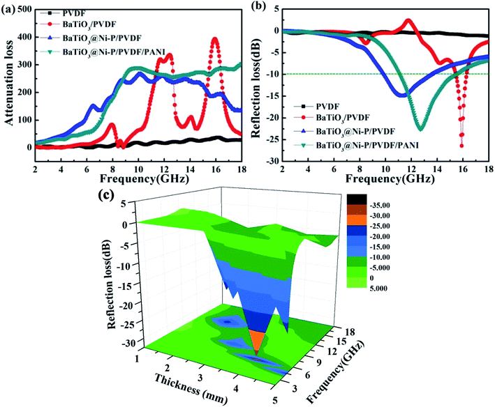 |
| | Fig. 7 (a) Attenuation constant α of the samples, (b) reflection loss of the samples with a thickness of 2 mm, and (c) reflection loss of BaTiO3@Ni–P/PVDF/PANI with different thickness. | |
Fig. 7b shows the RL of the composites with a thickness of 2 mm within the frequency range of 2–18 GHz. The minimum RL value of BaTiO3/PVDF reaches −26.4 dB at 15.90 GHz. However, the valid frequency bandwidth when RL < −10 dB is only 0.75 GHz (15.46–16.21 GHz). With the Ni–P coating, the RL of BaTiO3@Ni–P/PVDF improved considerably within the range of 2–15.2 GHz, the valid frequency was extended to 3.63 GHz (9.93–13.56 GHz), and the minimum RL was −14.99 dB at 11.27 GHz. For BaTiO3@Ni–P/PVDF/PANI, the minimum RL shifted to a high frequency, which reached −22.56 dB at 12.72 GHz. The valid frequency bandwidth was 4.33 GHz (11.12–15.45 GHz), which is wider than those of other absorbers, such as β-MnO2/PVDF (2.08 GHz),44 and ferrite/CNT/epoxy (3.27 GHz).45 This result can be ascribed to the aligned PANI, which improves the impedance matching properties of the composites. In addition, multi-interface polarization and synergistic effect are favorable for microwave absorption properties. The comparison of the RL values of the samples indicates that microwave properties improve significantly with a coating of Ni–P layer and the growth of aligned PANI.
Fig. 7c shows the microwave absorption performance of BaTiO3@Ni–P/PVDF/PANI with a thickness of 1–5 mm. The RL peaks visibly shift from a high frequency to a low frequency with increasing thickness. This phenomenon can be explained by the 1/4 wavelength equation (tm = nc/4f(εrμr)1/2).46 Hence, the absorption frequency range can be tuned by changing the thickness of the composites to satisfy practical application. For comparison, the microwave absorption performances of BaTiO3/PVDF and BaTiO3@Ni–P/PVDF are shown in Fig. S8.† In addition, BaTiO3@Ni–P/PVDF/PANI films with different filler loadings (30 wt% and 50 wt% BaTiO3@Ni–P powder were loaded onto PVDF) are shown in Fig. S9.† The results indicate that the microwave absorption properties of the composite films can be significantly improved by increasing filler loading. To avoid further increase in the density of films, 70 wt% filler loading is selected for this study.
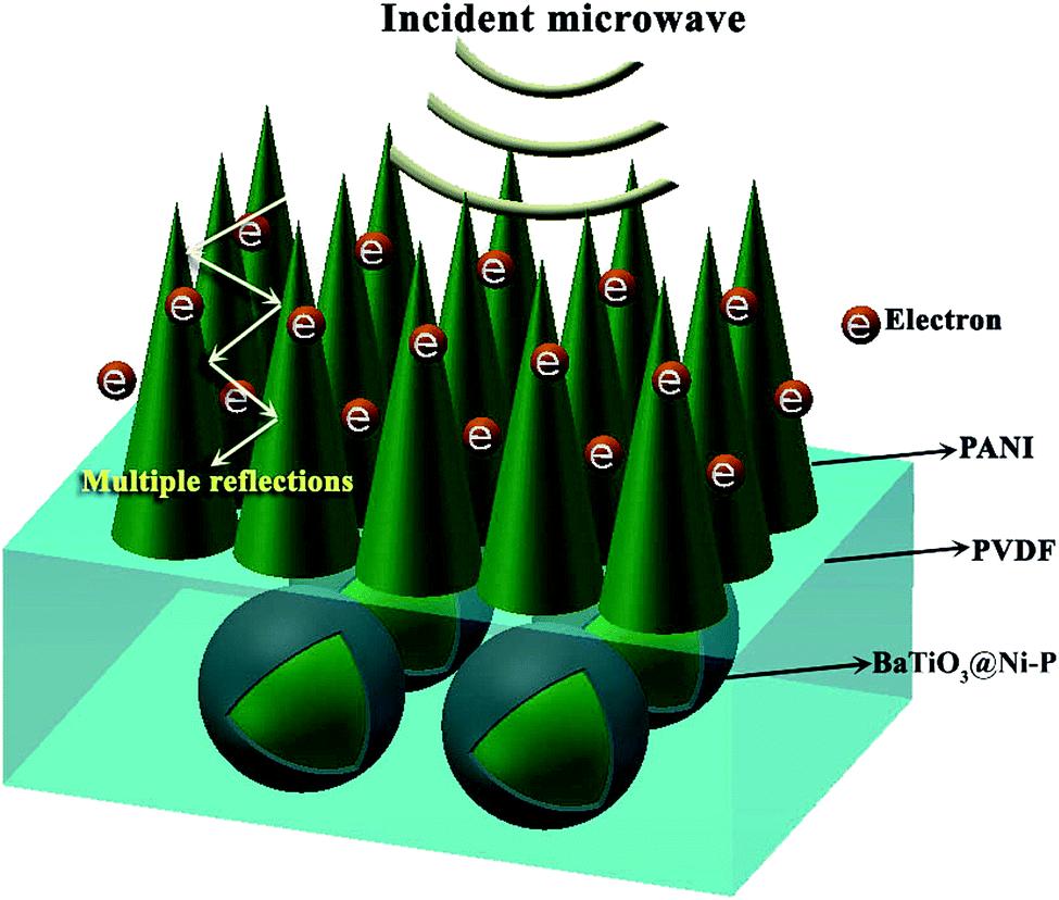
The exceptional microwave absorption performance of BaTiO3@Ni–P/PVDF/PANI may originate from the factors illustrated in Fig. 8. On the one hand, the aligned structure of PANI not only works to match characteristic impedance but also provides relatively large specific surface areas that can create additional active sites for the reflection of microwave. Consequently, the propagation path of EW can be extended effectively and a high amount of microwave energy is transformed into heat energy. On the other hand, microcurrent is generated when incident microwave reaches the surface of the conducting PANI. Such electron transmission procedure contributes to microwave absorption properties. Furthermore, natural resonance, dipole polarization and strong multi-interface polarization among components are all favorable to microwave absorption properties.
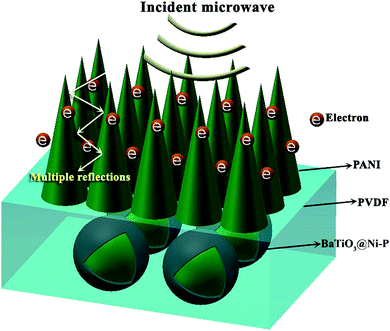 |
| | Fig. 8 Schematic illustration of the absorption mechanism of BaTiO3@Ni–P/PVDF/PANI. | |
4. Conclusion
In summary, BaTiO3@Ni–P core–shell structure and aligned PANI were synthesized via electroless deposition technology and dilute polymerization process, respectively. Flexible BaTiO3@Ni–P/PVDF/PANI composite films were fabricated through embedding and growing approaches. The BaTiO3@Ni–P/PVDF/PANI composite exhibits exceptional microwave absorption properties within the frequency range of 2–18 GHz, which is attributed to the unique structure and the dielectric and magnetic loss. The minimum RL value reaches −22.56 dB at 12.72 GHz. When RL < −10 dB, the bandwidths are 4.33 GHz (11.12–15.45 GHz) with a thickness of 2 mm. The MAM developed here in this study is promising for industrial-scale applications and in the military field given its strong absorption, broad band and lightweight properties.
Acknowledgements
This work is supported by National Natural Science Foundation of China (No. 51503183) and Zhejiang Provincial Natural Science Foundation of China (No. LQ14E030010).
References
- J. Wei, S. Zhang, X. Y. Liu, J. Qian, J. S. Hua, X. X. Li and Q. X. Zhuang, J. Mater. Chem. C, 2015, 3, 8205–8214 CAS.
- J. Qiu and T. T. Qiu, Carbon, 2015, 81, 20–28 CrossRef CAS.
- W. Q. Cao, X. X. Wang, J. Yuan, W. Z. Wang and M. S. Cao, J. Mater. Chem. C, 2015, 3, 10017–10022 RSC.
- X. M. Meng, X. J. Zhang, C. Lu, Y. F. Pan and G. S. Wang, J. Mater. Chem. A, 2014, 2, 18725–18730 CAS.
- H. L. Lv, G. B. Ji, X. H. Liang, H. Q. Zhang and Y. W. Du, J. Mater. Chem. C, 2015, 3, 5056–5064 RSC.
- R. L. Ji, C. B. Cao, Z. Chen, H. Z. Zhai and J. Bai, J. Mater. Chem. C, 2014, 2, 5944–5953 RSC.
- R. Qiang, Y. C. Du, Y. Wang, N. Wang, C. H. Tian, J. Ma, P. Xu and X. J. Han, Carbon, 2016, 98, 599–606 CrossRef CAS.
- S. C. Zhao, Z. Gao, C. Q. Chen, G. Z. Wang, B. Zhang, Y. Chen, J. Zhang, X. Li and Y. Qin, Carbon, 2016, 98, 196–203 CrossRef CAS.
- W. Choi, G. Yang, S. L. Kim, P. Liu, H. J. Sue and C. Yu, J. Power Sources, 2016, 313, 128–133 CrossRef CAS.
- F. F. Xu, L. Ma, Q. S. Huo, M. Y. Gan and J. H. Tang, J. Magn. Magn. Mater., 2015, 374, 311–316 CrossRef CAS.
- Y. J. Li, L. Ma, M. Y. Gan, J. H. Tang, H. F. Hu, C. Q. Ge, L. Yu, H. Huang and F. F. Yang, Mater. Lett., 2015, 140, 192–195 CrossRef CAS.
- F. Xia, J. W. Liu, D. Gu, P. F. Zhao, J. Zhang and R. C. Che, Nanoscale, 2011, 3, 3860–3867 RSC.
- X. D. Chen, G. Q. Wang, Y. P. Duan and S. H. Liu, J. Alloys Compd., 2008, 453, 433–436 CrossRef CAS.
- H. L. Lv, G. B. Ji, W. Liu, H. Q. Zhang and Y. W. Du, J. Mater. Chem. C, 2015, 3, 10232–10241 RSC.
- L. X. Ma, G. Q. Wang, L. D. Liu and B. Y. Li, J. Alloys Compd., 2010, 505, 374–378 CrossRef CAS.
- Y. K. Liu, Y. J. Feng, X. W. Wu and X. G. Han, J. Alloys Compd., 2009, 472, 441–445 CrossRef CAS.
- G. Q. Wang, L. X. Ma, Y. F. Chang and C. Liu, Appl. Surf. Sci., 2012, 258, 3962–3966 CrossRef CAS.
- Y. C. Qing, W. C. Zhou, F. Luo and D. M. Zhu, J. Magn. Magn. Mater., 2011, 323, 600–606 CrossRef CAS.
- R. G. Yang, J. Magn. Magn. Mater., 2011, 323, 1805–1810 CrossRef CAS.
- Y. F. Zhu, Y. Q. Fu, T. Natsuki and Q. Q. Ni, Polym. Compos., 2013, 34, 265–273 CrossRef CAS.
- Q. Q. Ni, Y. F. Zhu, L. J. Yu and Y. Q. Fu, Nanoscale Res. Lett., 2015, 10, 1–8 CrossRef CAS PubMed.
- Y. F. Zhu, Q. Q. Ni, Y. Q. Fu and T. Natsuki, J. Nanopart. Res., 2013, 15, 1–11 Search PubMed.
- X. Zhang, S. Y. Wei, N. Haldolaarachchige, H. A. Colorado, Z. P. Luo, D. P. Young and Z. H. Guo, J. Phys. Chem. C, 2012, 116, 15731–15740 CAS.
- L. Wang, J. F. Zhu, H. B. Yang, F. Wang, Y. Qin, T. Zhao and P. Zhang, J. Alloys Compd., 2015, 634, 232–238 CrossRef CAS.
- H. B. Yang, T. Ye, Y. Lin and M. Liu, Synth. Met., 2015, 210, 245–250 CrossRef CAS.
- L. W. Jiang, Z. H. Wang, D. Li, D. Y. Geng, Y. Wang, J. An, J. He, W. Liu and Z. D. Zhang, RSC Adv., 2015, 5, 40384–40392 RSC.
- Y. Wang, X. M. Wu and W. Z. Zhang, Mater. Lett., 2016, 165, 71–74 CrossRef CAS.
- Y. Z. Wei, G. S. Wang, Y. Wu, Y. H. Yue, J. T. Wu, C. Lu and L. Guo, J. Mater. Chem. A, 2014, 2, 5516–5524 CAS.
- G. S. Wang, X. J. Zhang, Y. Z. Wei, S. A. He, L. Guo and M. S. Cao, J. Mater. Chem. A, 2013, 1, 7031–7036 CAS.
- X. J. Zhang, G. S. Wang, Y. Z. Wei, L. Guo and M. S. Cao, J. Mater. Chem. A, 2013, 1, 12115–12122 CAS.
- X. J. Zhang, G. S. Wang, W. Q. Cao, Y. Z. Wei, J. F. Liang, L. Guo and M. S. Cao, ACS Appl. Mater. Interfaces, 2014, 6, 7471–7478 CAS.
- Y. F. Zhu, L. Zhang, T. Natsuki, Y. Q. Fu and Q. Q. Ni, ACS Appl. Mater. Interfaces, 2012, 4, 2102–2106 Search PubMed.
- Y. Lei, J. Li, Y. Y. Wang, L. Gu, Y. F. Chang, H. Y. Yuan and D. Xiao, ACS Appl. Mater. Interfaces, 2016, 6, 1773–1780 Search PubMed.
- G. W. Chen, Y. Z. Gao and H. Zhang, RSC Adv., 2016, 6, 30488–30497 RSC.
- Q. Liu, S. Gu and C. M. Li, J. Power Sources, 2015, 299, 342–346 CrossRef CAS.
- Q. Y. Yu, Z. X. Zeng, W. J. Zhao, Y. C. Ma, X. D. Wu and Q. J. Xue, ACS Appl. Mater. Interfaces, 2014, 6, 1053–1060 CAS.
- J. J. Xu, K. Wang, S. Z. Zu, B. H. Han and Z. X. Wei, ACS Nano, 2010, 4, 5019–5026 CrossRef CAS PubMed.
- X. F. Liu, Y. X. Chen, X. R. Cui, M. Zeng, R. H. Yu and G. S. Wang, J. Mater. Chem. A, 2015, 3, 12197–12204 CAS.
- D. L. Zhao, X. Li and Z. M. Shen, Mater. Sci. Eng., B, 2008, 150, 105–110 CrossRef CAS.
- B. Zhao, G. Shao, B. B Fan, W. Y. Zhao and R. Zhang, RSC Adv., 2014, 4, 57424–57429 RSC.
- M. Wang, G. B. Ji, B. S. Zhang, D. M. Tang, Y. Yang and Y. W. Du, J. Magn. Magn. Mater., 2015, 377, 52–58 CrossRef CAS.
- H. L. Lv, X. H. Liang, G. B. Ji, H. Q. Zhang and Y. W. Du, ACS Appl. Mater. Interfaces, 2015, 7, 9776–9783 CAS.
- M. Fu, Q. Z. Jiao, Y. Zhao and H. S. Li, J. Mater. Chem. A, 2014, 2, 735–744 CAS.
- Y. Niu and X. P. Li, Inorg. Chem. Commun., 2015, 55, 25–29 CrossRef CAS.
- S. Tyagi, P. Verma, H. B. Baskey, R. C. Agarwala, V. Agarwala and T. C. Shami, Ceram. Int., 2012, 38, 4561–4571 CrossRef CAS.
- H. Lv, G. B. Ji, H. Q. Zhang and Y. W. Du, RSC Adv., 2015, 5, 76836–76843 RSC.
Footnote |
| † Electronic supplementary information (ESI) available. See DOI: 10.1039/c7ra05744j |
|
| This journal is © The Royal Society of Chemistry 2017 |
Click here to see how this site uses Cookies. View our privacy policy here. 
 Open Access Article
 This Open Access Article is licensed under a
  ,
Yaofeng Zhu* and
Yaqin Fu
,
Yaofeng Zhu* and
Yaqin Fu