 Open Access Article
Facile fabrication of layer-cake-like nano-micro hierarchical structure for high performance Li storage†
Lihui Mou‡
a,
Jia Yu‡bc,
Lili Liu*a,
Xiuyun Zhang d and
Shimou Chen
 *bc
*bc
aKey Laboratory of Cosmetic, China National Light Industry, School of Science, Beijing Technology and Business University, Beijing 100048, China. E-mail: liulili@btbu.edu.cn
bBeijing Key Laboratory of Ionic Liquid Clean Process, Key Laboratory of Green Process and Engineering, Institute of Process Engineering, Chinese Academy of Sciences, Beijing 100190, China. E-mail: chenshimou@ipe.ac.cn
cUniversity of Chinese Academy of Sciences, Beijing 100049, China
dCollege of Physics Science and Technology, Yangzhou University, Yangzhou 225002, China
First published on 30th May 2017
Abstract
In this work, a cobalt-based nano-micro hierarchical structure is prepared via a facile one-pot hydrothermal process. Showing similar morphology to the traditional Chinese food “thousand-layer-cake”, it integrates both the advantages of microscale size and nanoscale design to achieve an efficient balance between Li storage capacity and tap density. On the one hand, its microscale overall dimensions are beneficial to a high tap density, and prevent excess formation of SEI film. On the other hand, its nanoscale building units and inner voids provide a shortened electron diffusion path and sufficient free space to buffer the volume variation during cycles. After calcination and coating processes, the final Co3O4/C exhibited a capacity as high as 739 mA h g−1 after 150 cycles, accompanied by excellent long-term cycle stability and rate performance. This layer-cake-like design may provide new ideas for low-cost synthesis of high tap density anode materials for lithium ion batteries.
Introduction
Driven by continuously increasing demands for high energy density batteries to be applied in electric vehicles and portable electronics, much attention has been paid to developing high capacity electrode materials for next-generation lithium ion batteries (LIBs).1–3 Benefiting from their easily accessible Li+, short diffusion path and large free space, nanostructure electrodes generally show high specific gravimetric capacity and rate capability, and thus are considered as promising candidates.4,5 However, other challenges still exist: the nanostructure design usually leads to too-large electrode/electrolyte interfaces, which results in excess formation of a solid electrolyte interface (SEI) layer,6 and the electrodes suffer from low tap density caused by the large interparticle space and specific surface area.7 This will give rise to capacity fade after long-term cycling, and result in batteries with an undesirable thickness. As major impediments to commercialization, these issues largely offset the advantages of nanostructure electrodes over traditional materials such as graphite anodes.To solve the problems caused by the intrinsic nature of nanostructure electrodes, fabricating nano-micro hierarchical structures has been proposed as a promising strategy,6–12 and several efficient architectures have been reported including pomegranate-,6 watermelon-,8 and plum-pudding-like structures.12 These typically show excellent capacity and rate performance benefiting from their nanoscale structure, while maintaining the advantages of SEI formation and packing density afforded by their microscale dimensions. For example, Guo et al. fabricated watermelon-like Si/C hierarchical microspheres by combining spray-drying and CVD processes.8 Elsewhere, Guo et al. reported LiFePO4/carbon hierarchical microtubes via calcination of composite fibers.11 Both of the above materials exhibited ideal electrochemical performance. However, traditional synthesis strategies usually either require complex multi-step processes,8 or give rise to too-large interspaces and void spaces and thus low tap density.11,13 Therefore, constructing a viable nano-micro hierarchical system with targeted properties remains a challenge and is highly dependent on the choice of compositional unit, architecture design and synthetic route.
Recently transition metal oxides (TMOs) have attracted much attention as LIB anode materials, such as Co3O4, FeO, CuO, etc.14–16 On the one hand, TMOs exhibit much higher theoretical capacities (∼800 mA h g−1) than that of commercial graphite electrodes (370 mA h g−1), due to their unique conversion mechanism for Li storage.14 More importantly, their morphology and composition have superior adjustability via hydrothermal synthesis, to enable construction of the desired structure.17,18 On the other hand, their nano-micro hierarchical architecture is beneficial for solving several key problems suffered by TMOs, including repeated SEI formation, huge volume variation during Li+ insertion/deinsertion and limited diffusion kinetics.4,10,15,19
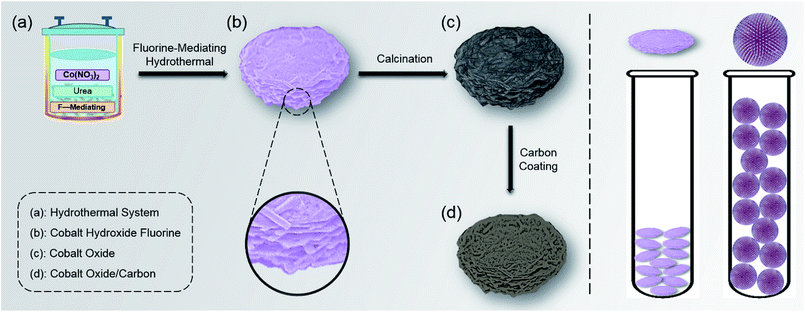
In this work, a layer-cake-like cobalt-based nano–micro hierarchical structure was prepared via a facile one-pot, fluorine-mediated hydrothermal process (Scheme 1). This structure was able to gain an efficient balance between Li storage capacity and tap density through integrating both the advantages of microscale size and nanoscale design. Concretely, the microsized dimensions gave rise to a high apparent tap density which was about 3 times that of the classical pompon-like structure, and prevented excess formation of SEI film caused by a too-large electrode/electrolyte interface, thus being beneficial for the volumetric energy density and capacity retention. Meanwhile, the nanosized building units and inner void shortened the diffusion pathway for Li+ and electrons, and buffered the expansion stress during lithium insertion. Moreover, as a common post-treatment process for anodes, carbon coating further improved the rate capability and cycle stability by enhancing electrical conduction and stabilizing the electrode interface.20,21 The final obtained layer-cake-like Co3O4/C structure showed a good Li-storage capacity and excellent cycle stability under a high area mass loading. Benefiting from its unique structure, the layer-cake-like design based on cobalt oxide and corresponding facile synthesis process have great potential in high tap density Li storage.
Experimental
Preparation methods
In a typical synthesis process, firstly cobalt nitrate hexahydrate (Co(NO3)2·6H2O), urea (CO(NH2)2) and ammonium fluoride (NH4F) were dissolved in 40 mL of deionized water with a molar ratio of 1![[thin space (1/6-em)]](https://www.rsc.org/images/entities/char_2009.gif) :
:![[thin space (1/6-em)]](https://www.rsc.org/images/entities/char_2009.gif) 5
5![[thin space (1/6-em)]](https://www.rsc.org/images/entities/char_2009.gif) :
:![[thin space (1/6-em)]](https://www.rsc.org/images/entities/char_2009.gif) 20, and then the solution was transferred into a 50 mL Teflon-lined stainless steel autoclave. After being heated at 180 °C for 6 h, the obtained product was washed with deionized water and ethanol several times followed by drying at 80 °C. The as-prepared layer-cake-like Co3O4 nano-micro hierarchical structure was obtained after calcination at 550 °C for 3 h under air atmosphere, with the colour changing from mauve to black. For the carbon coating treatment, 0.20 g of as-synthesized Co3O4 was dispersed in 35 mL of 1.0 M glucose solution by ultrasonication. Subsequently the suspension was transferred into the autoclave and heated at 180 °C for 3 h. After washing and drying, the resulting powder was carbonized at 500 °C for 3 h under nitrogen atmosphere to obtain the Co3O4/C composite.
20, and then the solution was transferred into a 50 mL Teflon-lined stainless steel autoclave. After being heated at 180 °C for 6 h, the obtained product was washed with deionized water and ethanol several times followed by drying at 80 °C. The as-prepared layer-cake-like Co3O4 nano-micro hierarchical structure was obtained after calcination at 550 °C for 3 h under air atmosphere, with the colour changing from mauve to black. For the carbon coating treatment, 0.20 g of as-synthesized Co3O4 was dispersed in 35 mL of 1.0 M glucose solution by ultrasonication. Subsequently the suspension was transferred into the autoclave and heated at 180 °C for 3 h. After washing and drying, the resulting powder was carbonized at 500 °C for 3 h under nitrogen atmosphere to obtain the Co3O4/C composite.
As a comparison sample for tap density, a Co-based radial pompon-like structure was prepared using a hydrothermal system containing the same starting materials (cobalt nitrate hexahydrate, urea and ammonium fluoride) but at a molar ratio of 2![[thin space (1/6-em)]](https://www.rsc.org/images/entities/char_2009.gif) :
:![[thin space (1/6-em)]](https://www.rsc.org/images/entities/char_2009.gif) 5
5![[thin space (1/6-em)]](https://www.rsc.org/images/entities/char_2009.gif) :
:![[thin space (1/6-em)]](https://www.rsc.org/images/entities/char_2009.gif) 2. The reaction conditions were equivalent to those for the layer-cake-like structure.
2. The reaction conditions were equivalent to those for the layer-cake-like structure.
Structural and compositional characterizations
Scanning electron microscopy (SEM) observation was performed on an SU8020 microscope (Hitachi, Japan) operated at 5.0 kV. Transmission electron microscopy (TEM) observation was performed with a JEM-2100F microscope (JEOL, Japan) operated at 200 kV. X-ray diffraction (XRD) patterns were recorded using the SmartLab 9 kW X-ray diffractometer (Rigaku, Japan) at a 2θ range between 15° and 70°. X-ray photoelectron spectroscopy (XPS) data were obtained using the ESCALAB 250Xi (Thermo Fisher Scientific, U.S.A.). Thermogravimetric (TG) analysis was performed using the DTG-60H (Shimadzu, Japan) under air atmosphere at a heating rate of 5 °C min−1. Energy dispersive spectroscopy (EDS) elemental mapping was performed using the X-MaxN (Oxford, U.K.) attached to the SU8020 operated at 20.0 kV.Electrochemical measurements
Electrochemical measurements were performed at room temperature using coin-type half-cells. Active material, Super P and polyvinylidene fluoride (PVDF) were mixed with a weight ratio of 80![[thin space (1/6-em)]](https://www.rsc.org/images/entities/char_2009.gif) :
:![[thin space (1/6-em)]](https://www.rsc.org/images/entities/char_2009.gif) 10
10![[thin space (1/6-em)]](https://www.rsc.org/images/entities/char_2009.gif) :
:![[thin space (1/6-em)]](https://www.rsc.org/images/entities/char_2009.gif) 10, followed by being pasted onto copper foil and dried at 80 °C. The mass of active material was measured as the weight difference between the electrode piece and an equivalent piece of bare copper foil, revealing a high average mass loading level of 4.5 mg per piece. Lithium foil was used as the counter electrode, and a Celgard 2400 membrane was used to separate the working electrode and counter electrode. The electrolyte was 1 mol L−1 of LiPF6 in an EC/DEC/DMC mixture (1
10, followed by being pasted onto copper foil and dried at 80 °C. The mass of active material was measured as the weight difference between the electrode piece and an equivalent piece of bare copper foil, revealing a high average mass loading level of 4.5 mg per piece. Lithium foil was used as the counter electrode, and a Celgard 2400 membrane was used to separate the working electrode and counter electrode. The electrolyte was 1 mol L−1 of LiPF6 in an EC/DEC/DMC mixture (1![[thin space (1/6-em)]](https://www.rsc.org/images/entities/char_2009.gif) :
:![[thin space (1/6-em)]](https://www.rsc.org/images/entities/char_2009.gif) 1
1![[thin space (1/6-em)]](https://www.rsc.org/images/entities/char_2009.gif) :
:![[thin space (1/6-em)]](https://www.rsc.org/images/entities/char_2009.gif) 1 in weight). To recycle the coin cells, they were discharged to 0.01 V (vs. Li/Li+) and recharged to 3.0 V (vs. Li/Li+) on the Neware battery testing system with various current densities. Cyclic voltammetry (CV) data were recorded on the Autolab (PGSTAT302N) electrochemical workstation, with a scanning rate of 0.1 mV s−1 and a voltage range of 0.01–3.0 V (vs. Li/Li+). Electrochemical impedance spectroscopy (EIS) measurements were carried out on the ACM Gill-AC-4 electrochemical station. After the cycle test, the electrode was washed using electrolyte to observe the morphology.
1 in weight). To recycle the coin cells, they were discharged to 0.01 V (vs. Li/Li+) and recharged to 3.0 V (vs. Li/Li+) on the Neware battery testing system with various current densities. Cyclic voltammetry (CV) data were recorded on the Autolab (PGSTAT302N) electrochemical workstation, with a scanning rate of 0.1 mV s−1 and a voltage range of 0.01–3.0 V (vs. Li/Li+). Electrochemical impedance spectroscopy (EIS) measurements were carried out on the ACM Gill-AC-4 electrochemical station. After the cycle test, the electrode was washed using electrolyte to observe the morphology.
Results and discussion
Synthetic procedure and mechanism
The synthetic procedure and proposed mechanism were as follows. As a prerequisite to formation of a uniform layer-cake structure in the homogeneous hydrothermal system, the fluorine-mediation effect played a significant role (Scheme 1a).22,23 During the initial stage, the cobaltous ions (Co2+) firstly combined with the fluorine ions (F−) to form the CoF+ complex (eqn (1)).23 As the solution temperature increased, the hydrolysis of urea (CO(NH2)2), which served as a slow-release pH adjusting agent, was accelerated to generate excess hydroxyl anions (OH−) (eqn (2)).24 Subsequently CoF+ combined with the OH− to precipitate into the cobaltous hydroxide fluoride Co(OH)F precursor (eqn (3)), which exhibited a microsized layer-cake-shaped morphology consisting of nanosized sheets (Scheme 1b). The relevant chemical reactions were as follows.| Co2+ + F− → CoF+ | (1) |
| CO(NH2)2 + 3H2O → 2NH4+ + 2OH− + CO2 | (2) |
| CoF+ + OH− → Co(OH)F↓ | (3) |
During this hydrothermal stage, the cobalt-based precursor was nucleated and grew. It is worth noting that the initial molar ratio of F− to Co2+ in the hydrothermal system influenced the precursor morphology to a large extent. When the F−/Co2+ ratio was decreased from 20 to 1, the precursor was transformed from a layer-cake-shape to a radial pompon-shape. Different morphologies resulted from different precursor compositions, which will be discussed in the following characterization.
After simple calcination, the Co(OH)F precursor was converted into Co3O4 (eqn (4)). Before testing its electrochemical properties, it was further coated with amorphous carbon, to form a Co3O4/C composite. Glucose was selected as the carbon source, since it is low-cost and can prevent the chaotic coalescence or aggregation of Co3O4/C by favouring particle separation.25,26 The relevant chemical reaction was as follows.
| 6Co(OH)F + O2 → 2Co3O4 + 6HF | (4) |
Morphology characterization
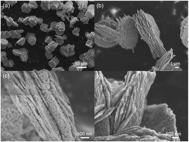
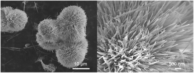
The morphologies of the precursor and products at various stages were observed by SEM. As shown in Fig. 1a, after the hydrothermal process, uniform round-cake-shaped precursors were obtained, which exhibited diameters of about 7–10 μm and thicknesses of 1.5–3 μm. In high-resolution observation, with its relatively smooth surface and coarse lateral sides, the multiple-layer morphology resembled the traditional Chinese food “thousand-layer-cake”. It consisted of sheet-shaped units whose thickness was as low as tens of nanometers, proving the successful fabrication of a nano-micro hierarchical structure. (Fig. 1b and S1 (ESI)†). The nanosheet building units and intersheet void spaces provided easier and greater access to Li+ and shortened the transport pathway, while efficiently buffering the volume expansion during Li+ insertion. The calcined product showed similar morphologies to the precursor, accompanied by plentiful nanopores on the surface. The formation of pores mainly resulted from the release of gas during calcination, and further enhanced the Li storage performance (Fig. 1c and S2†).27,28 After carbon coating treatment, the final Co3O4/C composite product maintained a consistent layer-cake-like structure, except for a slightly coarser surface (Fig. 1d and S3†).The above-mentioned layer-cake-like structure was obtained in a highly fluorine-enriched system (F−/Co2+ ratio of 20), however, the obtained precursor morphology varied markedly when the fluorine level was changed. Concretely, traditional pompon-like precursors were obtained when the initial F−/Co2+ ratio was decreased greatly to 1. They exhibited overall dimensions of about 10 μm, consisting of nanowires of diameter 40–60 nm which radially fanned out from the core (Fig. 2). The pompon-structure has been widely studied for LIB anodes based on TMOs, and generally achieves considerable Li storage capacities.29,30 However, the radial arrangement of nanowires (the basic structural components) inevitably leads to loose packing and thus low tap density. As shown in Fig. S4,† with the same precursor mass (300 mg), the layer-cake-structure occupied only about one third the volume of the pompon-structure, indicating the high tap density characteristic of the layer-cake-like design. In fact, its apparent tap density was comparable with the commercial graphite material. The architectural mechanism for the difference in packing density between the two structures is illustrated in Scheme 1. The high tap density efficiently enhanced the special volumetric capacity of the electrode, which was beneficial to improving the energy density of the battery system as a whole, showing great potential in practical applications.
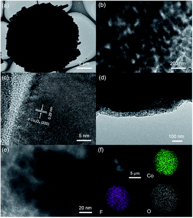
The layer-cake-like nano-micro hierarchical structure was further observed by TEM. For the calcined product Co3O4, Fig. 3a clearly demonstrates the round-cake structure of the final product Co3O4/C, with microscale dimensions, which is consistent with the SEM images. As shown in Fig. 3b, grains and voids with sizes of tens of nanometers were observed. This porous nature resulted from the precursor growth process and gas release during calcination, and the pores provided better access and shortened pathways for Li+ and electrons.27,28 In the high-resolution image, the dominant interplanar spacing of 0.29 nm belonged to the Co3O4 (220) lattice planes (Fig. 3c).30 In the final product Co3O4/C, a uniform carbon layer was coated on the surface of the Co3O4 particles, being favorable to the electrode interface stability and allowing extra interfacial lithium storage (Fig. 3d).31 And the porous structure was still evident (Fig. 3e). It was clear that the calcination and coating procedure caused no noticeable change in the overall morphology.32
Compositional characterization
To estimate the appropriate calcination treatment temperature for the precursor, the thermal behaviour of Co(OH)F was studied by TG analysis. Fig. 4a shows the TG curve under air with a temperature ramp of 5 °C min−1, in which the curve is monotonic and the most prominent weight loss took place above 350 °C. The final weight loss, reached at 550 °C, is about 17%, which is slightly larger than the theoretical value for decomposition of Co(OH)F into Co3O4 under air atmosphere, due to existence of crystalline water in the initial precursor. Similarly, the carbon content in the Co3O4/C final product was estimated to be about 16% by weight (Fig. S5†). In addition, the EDS element mapping of the precursor clearly evidenced its chemical composition through indicating the existence of Co, O and F (Fig. 3f).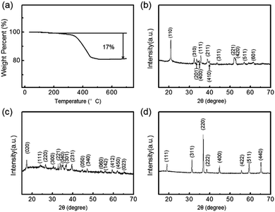 | ||
| Fig. 4 (a) TG curve of Co(OH)F precursor. XRD patterns of (b) Co(OH)F precursor, (c) Co(CO3)0.5(OH)·0.11H2O precursor and (d) Co3O4/C final product. | ||
The crystalline structures were further investigated by XRD to verify the successful fabrication of the final product. As shown in Fig. 4b, the diffraction peaks from 20.9° to 61.6° were all in good agreement with the (110), (310), (201), (400), (111), (211), (410), (311), (221), (420), (511) and (601) faces of orthorhombic Co(OH)F (JCPDS card no. 50-0827), confirming the precursor composition.24 For the final product, eight obvious diffraction peaks could be assigned to the (111), (220), (311), (222), (400), (422), (511) and (440) planes of cubic Co3O4 (JCPDS card no. 42-1467) (Fig. 4d).33 This was consistent with the above TG result and the proposed mechanism of precursor decomposition. There were no noticeable peaks with 2θ values near 26°, indicating that the carbon coating layer was amorphous.25,26 Compared with the precursor, the sharper peaks of the final product indicated high crystallinity and relatively large crystallite size after calcination.34 Moreover, the XRD pattern of the pompon-like precursor obtained from the low-fluorine hydrothermal system was consistent with orthorhombic Co(CO3)0.5(OH)·0.11H2O (JCPDS card no. 48-0083), exhibiting a chemical composition which totally differed from the layer-cake-structure (Fig. 4c).35
In addition, further information on the composition of the precursor and final product was obtained via XPS. Fig. 5a shows the full-survey XPS spectrum of the Co(OH)F precursor, in which sharp peaks assigned to O1s, F1s and Co2p were observed. Concerning the representative Co2p state, the peak at 783.4 eV corresponded to the Co2p3/2 state of Co(OH)F, while the two peaks of the Co2p1/2 state were located at higher binding energies (around 799.3 and 804.5 eV) (Fig. 5b).36,37 Concerning the F1s state, the peak at 686.0 eV was assigned to the lattice fluorine of Co(OH)F (Fig. 5c).22 The prominent O1s peak located at 532.3 eV could be attributed to the lattice oxygen of Co(OH)F (Fig. 5d).36 For the product Co3O4/C, the Co2p spectrum principally contained two major peaks located at binding energies of 781.3 and 796.3 eV, which corresponded to the Co2p3/2 and Co2p1/2 states respectively (Fig. S6a†).30 Meanwhile, the main O1s peak located at 530.9 eV was assigned to the O–Co bond in Co3O4 (Fig. S6b†).29
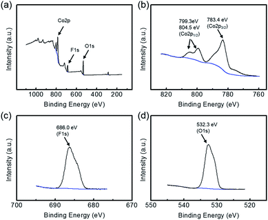 | ||
| Fig. 5 (a) Full-survey, (b) Co2p, (c) F1s and (d) O1s XPS characterizations of the precursor, further evidencing its chemical composition. | ||
Lithium storage performance
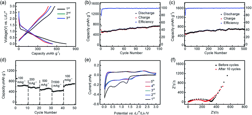
The lithium storage performance of the Co3O4/C nano-micro hierarchical structure as an LIB anode was evaluated using a two-electrode cell, where Co3O4/C and lithium metal served as the working electrode and counter electrode respectively. The conversion reaction mechanism could be described as follows: Co3O4 + 8Li+ + 8e− ↔ 3Co + 4Li2O.14As shown in Fig. 6a, with a current density of 100 mA g−1 and a voltage range of 0.01–3.0 V, the discharge voltage vs. capacity curve of the first cycle exhibited a plateau starting around 1.2 V followed by a downward sloping, which were ascribed to the Li storage in Co3O4 and the formation of an SEI film due to interaction with the electrolyte, respectively.33,38 In subsequent cycles, the plateau shifted to higher voltage and became less well-defined, while the curves became stable.39 It was observed that the initial discharge capacity was 745 mA h g−1, which would be close to the theoretical capacity of Co3O4 (890 mA h g−1) if the coating layer weight was further excluded. Besides intrinsic Li storage, the high discharge capacity was partially attributed to the extra interfacial Li storage and the consumption of Li+ due to SEI formation.31,40 Meanwhile, the charge capacity for the first cycle was 575 mA h g−1, accompanied by an initial coulombic efficiency of nearly 80%. This is a relatively high efficiency compared with conventional conversion-type anodes, and is attributed to the microscale overall dimensions, which prevent the formation of a too-large interface, and to the carbon coating layer.20,41 The irreversible capacity was mainly due to the incomplete decomposition of the SEI layer, and a possible kinetic limit to Li+ extraction.42,43
Fig. 6b shows the cycle performance of Co3O4/C at a current density of 100 mA g−1. It is found that the reversible capacities show an upward trend during the initial cycles, and reach a maximum discharge capacity of 739 mA h g−1 after 150 cycles. Meanwhile, the coulombic efficiency is maintained above 98% after several cycles, indicating the excellent Li storage capacity and superior cycling stability of the layer-cake-like Co3O4/C. When compared with the pompon-like structure of Co3O4 prepared in our previous work, the layer-cake-like structure showed obvious advantages in long-term capacity retention and initial coulombic efficiency, mainly owing to the carbon coating layer, and the more compact and stable framework. However, the pompon-like Co3O4 showed a higher specific capacity in the initial phase of cycling.30 Furthermore, when the current density was increased to 500 mA g−1, the discharge capacity still maintained a high value of 692 mA h g−1 after long-term cycling (500 cycles), with a high and stable coulombic efficiency (Fig. 6c). Similarly, it was observed to show excellent stability of electrode capacity retention after a gradually rising stage. The phenomenon of an initial stage of rising capacity, which is well-documented in other studies,33,39,40,44 was mainly due to the electrode activation effect, which is intrinsic to the conversion mechanism of TMO-based anodes, as well as the extra interfacial Li storage and reversible decomposition of the electrolyte.45 The desirable cycle stability can be mainly attributed to the unique nano-micro hierarchical structure, which simultaneously avoided the formation of a too-large electrode/electrolyte interface, facilitated the diffusion of Li+ and electrons, and resisted the volume expansion during cycles. In addition, the carbon coating treatment efficiently enhanced the electrode capacity retention through preventing the Co3O4 from directly contacting the electrolyte, and also resulted in better conductivity. Therefore, the advantage of the layer-cake-like Co3O4/C is most evident in its higher rate and longer-term cycling stability.
As shown in Fig. 6d, the discharge capacities at various current densities (between 100 and 1500 mA g−1) were further compared. The reversible capacity decreased monotonically as the rate increased. In particular, when tested at a high current density of 1500 mA g−1 it was able to deliver a discharge capacity of more than 420 mA h g−1. This meant that the discharge or charge process could be finished in about 16 min, while a capacity above that of commercial graphite was achieved. It was also found that the capacity at high rate reached more than two thirds of the initial capacity at low rate, indicating the superior rate capability. Moreover, the capacity recovered to more than 700 mA h g−1 when the rate returned to 100 mA g−1 after cycling at a high rate, further corroborating the excellent rate capability and capacity retention of the layer-cake structure. In addition, the used Co3O4/C electrode was characterized by SEM, revealing that its morphology and structure were well preserved after 500 cycles (Fig. S7†). This is because the nano-micro hierarchical architecture could effectively buffer the volume variation during the cycles, and the carbon coating layer helped to stabilize the inner Co3O4.
To investigate the electrochemical reactions during the Li+ insertion/deinsertion processes more explicitly, cyclic voltammetry (CV) curves of the electrode made from Co3O4/C were carried out in the potential range of 3.0–0.01 V vs. Li/Li+ at a scan rate of 0.1 mV s−1 (Fig. 6e). There were obvious peaks at 0.5–0.6 V and 1.2 V in the first cathodic scan, which were attributed to electrolyte decomposition and formation of an SEI layer.46 After the first scan, cathodic peaks at ∼0.9 V and ∼1.4 V and corresponding anodic peaks at ∼1.3 V and ∼2.2 V were observed. The reduction/oxidation reaction of Co2+/3+/Co0 is a complex multi-step process, because Co2+ and Co3+ ions occupy tetrahedral interstices and octahedral sites, respectively, of the cubic closely packed lattice of oxide anions in the spinel structure of Co3O4.27 In extended scans the peaks exhibited similar densities, indicating the excellent electrochemical stability of the Co3O4/C anode. The cathodic peaks below 0.1 V could be assigned to the lithiation of carbon.47 The Nyquist impedance plots of the electrodes before and after cycling are compared in Fig. 6f, wherein the depressed semicircles at high frequency and inclined lines at low frequency correspond to charge impedance and lithium diffusion impedance, respectively.48 It exhibited obviously decreased impedance values after the initial 10 cycles, which was attributed to the electrode activation, electrolyte immersion, and opening of Li+ diffusion channels.20
Discussion on structure and performance
Overall, it was observed that the Co3O4 exhibited excellent Li-storage performance during long-term and high-rate cycling, accompanied by a high tap density. The performance of the layer-cake-like Co3O4/C with nano-micro hierarchical structures can be attributed to the synergistic effect of several factors: (1) Co3O4 served as a high capacity Li-storage framework due to its conversion mechanism when compared with traditional intercalation-mechanism anodes, accompanied by extra interfacial lithium storage, which further enhanced the system energy density.14,31 (2) The microsized overall dimensions of the Co3O4/C avoided the formation of a too-large electrode/electrolyte contact interface, which controlled the excess formation of SEI and thus alleviated the Li+ consumption and capacity fade.6 Meanwhile, it guaranteed dense packing of particles, which gave rise to higher tap density than classical nanostructures such as the radial pompon-like structure. (3) The nanosized sheet-shaped building units and porous nature provided easier access and shortened diffusion paths for both Li+ and electrons, thus benefiting the rate capability. Moreover, there was sufficient free space to efficiently buffer the volume variation during Li+ insertion/deinsertion.15 (4) The carbon coating layer prevented direct contact between the inner Co3O4 and the electrolyte, working as an artificial SEI layer to avoid excessive consumption of Li+ and active material. It also helped to complement the low conductivity and resist the volume variation of the inner metal oxide.20,49Conclusions
In this work, we have synthesized layer-cake-like Co3O4/C with a nano-micro hierarchical structure via a facile process, for high performance Li-storage applications. Its microsized overall dimensions gave rise to a high apparent tap density, which was more than 3 times that of the classical pompon-like structure, while avoiding a too-large electrode/electrolyte contact interface to alleviate the capacity fade. Meanwhile, its nanosized sheet-shaped building units and porous nature provided easy access and shortened diffusion paths for both Li+ and electrons, and sufficient free space to buffer the volume variation during cycles. Benefiting from multiple factors, the Co3O4/C exhibited an excellent reversible capacity and cycle stability. With a current density of 100 mA g−1 it reached a capacity as high as 739 mA h g−1, while being able to stabilize around 690 mA h g−1 at a high rate of 500 mA g−1 during long-term cycling (500 cycles). We anticipate that this work may provide new ideas for the production of TMO-based LIB anodes with long-term cycle stability and high tap density.Acknowledgements
This work was supported by National Natural Science Foundation of China (Nos 21503006, 21276257, 91534109 and 11574262), the “Strategic Priority Research Program” of the Chinese Academy of Sciences (No. XDA09010103) and National Key Projects for Fundamental Research and Development of China (No. 2016YFB0100104).References
- M. N. Obrovac and V. L. Chevrier, Chem. Rev., 2014, 114, 11444–11502 CrossRef CAS PubMed.
- N. W. Li, Y. X. Yin, C. P. Yang and Y. G. Guo, Adv. Mater., 2016, 28, 1853–1858 CrossRef CAS PubMed.
- X. B. Cheng, T. Z. Hou, R. Zhang, H. J. Peng, C. Z. Zhao, J. Q. Huang and Q. Zhang, Adv. Mater., 2016, 28, 2888–2895 CrossRef CAS PubMed.
- Y. X. Tang, Y. Y. Zhang, W. L. Li, B. Ma and X. D. Chen, Chem. Soc. Rev., 2015, 44, 5926–5940 RSC.
- X. J. Wang, J. Feng, Y. C. Bai, Q. Zhang and Y. D. Yin, Chem. Rev., 2016, 116, 10983–11060 CrossRef CAS PubMed.
- N. Liu, Z. D. Lu, J. Zhao, M. T. McDowell, H. W. Lee, W. T. Zhao and Y. Cui, Nat. Nanotechnol., 2014, 9, 187–192 CrossRef CAS PubMed.
- D. C. Lin, Z. D. Lu, P. C. Hsu, H. R. Lee, N. Liu, J. Zhao, H. T. Wang, C. Liu and Y. Cui, Energy Environ. Sci., 2015, 8, 2371–2376 CAS.
- Q. Xu, J. Y. Li, J. K. Sun, Y. X. Yin, L. J. Wan and Y. G. Guo, Adv. Energy Mater., 2017, 7, 1601481 CrossRef.
- S. Chae, M. Ko, S. Park, N. Kim, J. Ma and J. Cho, Energy Environ. Sci., 2016, 9, 1251–1257 CAS.
- J. Ryu, D. Hong, M. Shin and S. Park, ACS Nano, 2016, 10, 10589–10597 CrossRef CAS PubMed.
- Y. H. Zou, S. Chen, X. F. Yang, N. Ma, Y. Z. Xia, D. J. Yang and S. J. Guo, Adv. Energy Mater., 2016, 6, 1601549 CrossRef.
- G. L. Hou, B. L. Chen, Y. B. Cao, M. S. Yao, B. Q. Li, C. Zhang, Q. H. Weng, X. Wang, Y. Bando, D. Golberg and F. L. Yuan, Nano Energy, 2016, 24, 111–120 CrossRef CAS.
- Y. P. Zhu, T. Y. Ma, M. Jaroniec and S. Z. Qiao, Angew. Chem., Int. Ed., 2017, 56, 1324–1328 CrossRef CAS PubMed.
- V. Aravindan, Y. S. Lee and S. Madhavi, Adv. Energy Mater., 2015, 5, 1402225 CrossRef.
- J. Yu, S. M. Chen, W. J. Hao and S. J. Zhang, ACS Nano, 2016, 10, 2500–2508 CrossRef CAS PubMed.
- X. Ge, C. D. Gu, X. L. Wang and J. P. Tu, J. Phys. Chem. C, 2014, 118, 911–923 CAS.
- Y. Wang and G. Z. Cao, Adv. Mater., 2008, 20, 2251–2269 CrossRef CAS.
- X. H. Xia, J. P. Tu, Y. Q. Zhang, X. L. Wang, C. D. Gu, X. B. Zhao and H. J. Fan, ACS Nano, 2012, 6, 5531–5538 CrossRef CAS PubMed.
- H. J. Qiu, L. Liu, Y. P. Mu, H. J. Zhang and Y. Wang, Nano Res., 2015, 8, 321–339 CrossRef CAS.
- J. Yu, X. Wang, S. M. Chen, X. Y. Liu and S. J. Zhang, Nano Res., 2017, 10, 172–186 CrossRef CAS.
- H. Zhang, Y. Lu, C. D. Gu, J. B. Cai, X. L. Wang and J. P. Tu, Electrochim. Acta, 2013, 118, 472–479 CrossRef.
- W. M. Mei, J. Huang, L. P. Zhu, Z. Z. Ye, Y. J. Mai and J. P. Tu, J. Mater. Chem., 2012, 22, 9315–9321 RSC.
- L. P. Zhu, Z. Wen, W. M. Mei, Y. G. Li and Z. Z. Ye, J. Phys. Chem. C, 2013, 117, 20465–20473 CAS.
- L. Li, K. H. Seng, Z. X. Chen, Z. P. Guo and H. K. Liu, Nanoscale, 2013, 5, 1922–1928 RSC.
- N. Jayaprakash, W. D. Jones, S. S. Moganty and L. A. Archer, J. Power Sources, 2012, 200, 53–58 CrossRef CAS.
- X. W. Lou, D. Deng, J. Y. Lee and L. A. Archer, Chem. Mater., 2008, 20, 6562–6566 CrossRef CAS.
- W. Y. Li, L. N. Xu and J. Chen, Adv. Funct. Mater., 2005, 15, 851–857 CrossRef CAS.
- Y. C. Jiao, D. D. Han, L. M. Liu, L. Ji, G. N. Guo, J. H. Hu, D. Yang and A. G. Dong, Angew. Chem., Int. Ed., 2015, 54, 5727–5731 CrossRef CAS PubMed.
- S. L. Xiong, J. S. Chen, X. W. Lou and H. C. Zeng, Adv. Funct. Mater., 2012, 22, 861–871 CrossRef CAS.
- W. J. Hao, S. M. Chen, Y. J. Cai, L. Zhang, Z. X. Li and S. J. Zhang, J. Mater. Chem. A, 2014, 2, 13801–13804 CAS.
- Y. F. Zhukovskii, P. Balaya, E. A. Kotomin and J. Maier, Phys. Rev. Lett., 2006, 96, 058302 CrossRef PubMed.
- D. Q. Liu, X. Wang, X. B. Wang, W. Tian, Y. Bando and D. Golberg, Sci. Rep., 2013, 3, 2543 CrossRef PubMed.
- X. L. Xiao, X. F. Liu, H. Zhao, D. F. Chen, F. Z. Liu, J. H. Xiang, Z. B. Hu and Y. D. Li, Adv. Mater., 2012, 24, 5762–5766 CrossRef CAS PubMed.
- J. S. Cho, Y. J. Hong and Y. C. Kang, ACS Nano, 2015, 9, 4026–4035 CrossRef CAS PubMed.
- Y. Wang, H. Xia and J. Y Lin, ACS Nano, 2010, 4, 1425–1432 CrossRef CAS PubMed.
- C. C. Li, X. M. Yin, T. H. Wang and H. C. Zeng, Chem. Mater., 2009, 21, 4984–4992 CrossRef CAS.
- K. X. Yao and H. C. Zeng, J. Phys. Chem. C, 2009, 113, 1373–1385 CAS.
- A. K. Rai, L. T. Anh, J. Gim and J. Kim, Ceram. Int., 2013, 39, 9325–9330 CrossRef CAS.
- D. D. Li, L. X. Ding, S. Q. Wang, D. D. Cai and H. H. Wang, J. Mater. Chem. A, 2014, 2, 5625–5630 CAS.
- P. Poizot, S. Laruelle, S. Grugeon, L. Dupont and J. Tarascon, Nature, 2000, 407, 496–499 CrossRef CAS PubMed.
- M. E. Im, D. Pham-Cong, J. Y. Kim, H. S. Choi, J. H. Kim, J. P. Kim, J. Kim, S. Y. Jeong and C. R. Cho, J. Power Sources, 2015, 284, 392–399 CrossRef CAS.
- Y. S. Hu, R. Demir-Cakan, M. M. Titirici, J. O. Muller, R. Schlogl, M. Antonietti and J. Maier, Angew. Chem., Int. Ed., 2008, 47, 1645–1649 CrossRef CAS PubMed.
- M. V. Reddy, T. Yu, C. H. Sow, Z. X. Shen, C. T. Lim, G. V. S. Rao and B. V. R. Chowdari, Adv. Funct. Mater., 2007, 17, 2792–2799 CrossRef CAS.
- Y. G. Li, B. Tan and Y. Y. Wu, Nano Lett., 2008, 8, 265–270 CrossRef CAS PubMed.
- C. Peng, B. Chen, Y. Qin, S. Yang, C. Li, Y. Zuo, S. Liu and J. Yang, ACS Nano, 2012, 6, 1074–1081 CrossRef CAS PubMed.
- R. Z. Yang, Z. X. Wang, J. Y. Liu and L. Q. Chen, Electrochem. Solid-State Lett., 2004, 7, A496–A499 CrossRef CAS.
- L. Yang, S. Cheng, Y. Ding, X. B. Zhu, Z. L. Wang and M. L. Liu, Nano Lett., 2012, 12, 321–325 CrossRef CAS PubMed.
- W. W. Li, S. M. Chen, J. Yu, D. L. Fang, B. Z. Ren and S. J. Zhang, Green Energy & Environment, 2016, 1, 91–99 Search PubMed.
- J. Liu, P. Kopold, P. A. van Aken, J. Maier and Y. Yu, Angew. Chem., Int. Ed., 2015, 54, 9632–9636 CrossRef CAS PubMed.
Footnotes |
| † Electronic supplementary information (ESI) available: SEM images, apparent tap density comparison, TG curve, XPS data. See DOI: 10.1039/c7ra04326k |
| ‡ These authors contributed equally to this work. |
| This journal is © The Royal Society of Chemistry 2017 |

