 Open Access Article
Ionic liquid assisted hydrothermal synthesis of MoS2 double-shell polyhedral cages with enhanced catalytic hydrogenation activities†
Jiahe Li ab,
Donge Wanga,
Huaijun Maa,
Min Liab,
Zhendong Pana,
Yuxia Jiangab and
Zhijian Tian
 *ac
*ac
aDalian National Laboratory for Clean Energy, Dalian Institute of Chemical Physics, Chinese Academy of Sciences, Dalian 116023, China. E-mail: tianz@dicp.ac.cn; Fax: +86-411-84379151; Tel: +86-411-84379151
bUniversity of Chinese Academy of Sciences, Beijing 100049, China
cState Key Laboratory of Catalysis, Dalian Institute of Chemical Physics, Chinese Academy of Sciences, Dalian 116023, China
First published on 28th April 2017
Abstract
MoS2 double-shell polyhedral cages are synthesized via an ionic liquid assisted hydrothermal process, in which the polyhedral cages of organic–inorganic hybrid phosphomolybdic acid-ionic liquids (PMA-ILs) are formed in situ and serve as a sacrificial template. The as-synthesized MoS2 hierarchical polyhedral cages have a lateral length of 0.5–1.5 μm and average shell thickness of about 150 nm. The surfaces of MoS2 double-shell polyhedral cages are very rough and composed of small nanosheets. The synthesis parameters including ionic liquid dosage, crystallization time and sulfur source are investigated to clarify the growth mechanism. Polycyclic aromatic hydrocarbons including naphthalene and anthracene were used as model compounds to evaluate the catalytic hydrogenation performance of the as-synthesized MoS2 sample. It turns out that MoS2 double-shell polyhedral cages manifest better catalytic hydrogenation activities than MoS2 nanoparticles and commercial bulk MoS2. The double-shell hollow structure and the vertical-alignment of nanosheets in the polyhedral shell are responsible for the enhanced catalytic activities of MoS2 double-shell polyhedral cages.
1. Introduction
Over the last few decades, two-dimensional molybdenum sulfide (MoS2) materials have attracted considerable attention due to their intriguing properties and widespread applications in catalysis, optoelectronics, electrochemistry and hydrogen storage fields.1–6 In particular, MoS2-based materials have been extensively studied as effective hydrogenation catalysts for hydro-processing petroleum feed stock and upgrading heavy oil.7–10 Up to now, supported MoS2 catalysts have been extensively utilized for hydrogenation in a fixed-bed reactor.11–13 However, the catalytic activity falls rapidly because of coking and metal deposition during the reaction process.14,15 An alternative technology is slurry-phase hydrogenation process with highly dispersed unsupported catalysts.9,16,17 In a slurry-phase reactor filled with hydrogen, all the reactants and catalysts are well-mixed and the temperature distribution is highly homogeneous under vigorous stirring. It's worth noting that only a small amount of catalyst is added into the slurry bed reactor owing to its one-through operation. Thus exploring highly dispersed unsupported MoS2 catalysts with abundant active sites is an urgent subject.As a typical lamellar compound, MoS2 naturally exists as hexagonal structure, in which the atoms within the layer are held together by strong covalent forces while the S–Mo–S layers are loosely bound to each other by van der Waals forces. It has been demonstrated that the catalytic performance of MoS2 depends on the number of exposed active edge sites.18,19 Compared to bulky MoS2, micro/nano MoS2 catalysts can expose more active edge sites. Unfortunately, the agglomeration of MoS2 nanosheets is almost unavoidable in most cases because of the high surface energy and van der Waals attraction. In these cases, only the edge sites of the outmost nanosheets are available for catalysis while a large amount of inner nanosheets are wrapped, which means a very low density of exposed active sites.
One of the most effective solutions to solve this problem is assembling two dimensional nanosheets into hierarchical architectures with well alignment and open texture, in which most pristine nanosheets can be exposed and preserve high exposed active sites.20,21 Among various hierarchical architectures, hollow micro- and nano-structures are very advantageous to increase the active edge sites since they have unique internal void, low density, high surface-to-volume ratio and shell permeability.22,23 Up to now, spherical or quasi-spherical MoS2 hollow particles have been easily synthesized since the interface energy of sphere is relatively low.24–28 Recently, nonspherical MoS2 hollow cages have been constructed successfully. Xie and co-workers prepared MoS2 hierarchical hollow cubic cages assembled by bilayers via a one-step self-assembly process.29 The obtained MoS2 hierarchical hollow cubic cages exhibit outstanding electrochemical hydrogen storage properties due to abundant active edges exposing on the upright-standing nanoplates. Afterwards, MoS2 hollow cages with abundant geometrical morphologies were controllably synthesized by varying the surfactant concentrations.30 In another work, Lou and co-workers reported a facile template-assisted strategy for the synthesis of hierarchical MoS2 microboxes constructed by ultrathin nanosheets.21 Compared to single-shell hollow structure, double-shell structure with novel geometrical morphology may be beneficial to expose more active edge sites. However, to the best of our knowledge, there is no report on the preparation of MoS2 polyhedral hollow cages with double-shell structure. Besides, most studies about hollow materials focused on the electrochemistry performance.31,32 The influence of hollow structure on traditional catalytic performance of MoS2 materials needs to be studied further.
Herein, we report the synthesis of MoS2 double-shell polyhedral cages via a simple ionic liquid 1-ethyl-3-methylimidazolium bromide ([EMIM]Br) assisted hydrothermal route using phosphomolybdic acid (PMA) and glutathione (GSH) as Mo and S precursors, respectively. A possible growth mechanism of MoS2 double-shell polyhedral cages is presented based on the time-dependent experiments and contrast experiments. Anthracene and naphthalene were used as model compound to test the catalytic hydrogenation performance of as-synthesized MoS2 double-shell polyhedral cages, respectively. It turns out that MoS2 double-shell polyhedral cages manifest better activities than MoS2 nanoparticles and commercial bulk MoS2 in both reactions. It's speculated that the double-shell hollow structure and the way of nanosheet arrangement are advantageous to increase the number of exposed active sites, thus enhancing catalytic activities.
2. Experimental
2.1 Synthesis of MoS2 double-shell polyhedral cages
All chemicals were analytical reagents and used without further purification. In a typical procedure, 0.125 mmol of phosphomolybdic acid (PMA), 4.5 mmol of glutathione (GSH), and 7.85 mmol of [EMIM] Br were dissolved into 50 mL of deionized water. The resulting solution was transferred into a 100 ml Teflon-lined stainless steel autoclave, which was then heated at 200 °C for 24 h. After that, the autoclave was allowed to cool down to room temperature naturally. The black precipitates were filtered and washed with deionized water and absolute ethanol. The final product was dried at 70 °C overnight in a vacuum oven.2.2 Characterizations of MoS2 double-shell polyhedral cages
XRD analysis of the obtained samples was performed on a PANalytical X'Pert PRO diffractometer fitted with a CuKα radiation source (λ = 1.5418 Å) operating at 40 mA and 40 kV. Field-emission scanning electron microscope (FESEM) images were acquired on an FEI Quanta 200F and JSM-7800 microscope operated at 20 kV. Transmission electron microscopy (TEM) images were collected on a JEM 2100 instrument at an accelerating voltage of 200 kV. CHNS analysis was conducted on a Flash 2000 organic elemental analyzer. BET specific surface areas were measured on an ASAP 2420 instrument by nitrogen adsorption.2.3 Catalytic hydrogenation activities of MoS2 double-shell polyhedral cages
The evaluation of catalytic hydrogenation activity was performed in a 100 ml stirred Parr high pressure vessel. For anthracene hydrogenation, 30 g tridecane, 3 g anthracene and 0.075 g MoS2 catalysts were put into the autoclave. After discharging air with hydrogen for three times, the autoclave was pressured with hydrogen to 8.0 MPa at room temperature and then heated to 350 °C at a rate of 10 °C min−1. The reaction of anthracene hydrogenation was maintained at 350 °C for 4 h with stirring rate of 300 rpm. After cooling the autoclave naturally, the reaction mixtures were filtered to obtain liquid products. The filtrate was qualitatively analyzed with an Agilent 7890B/5977A GC/MS and quantitatively analyzed with an Agilent 7890A GC system. For naphthalene hydrogenation, the initial hydrogen pressure was 6.0 MPa, and the hydrogenation reaction was maintained at 300 °C for 6 h. The experimental operation was the same as anthracene hydrogenation.3. Results and discussion
3.1 Characterizations of MoS2 double-shell polyhedral cages
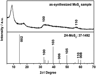
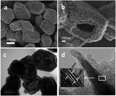
XRD pattern of as-synthesized MoS2 sample was shown in Fig. 1. Diffraction peaks at about 2θ = 32° and 58° can be assigned to (100) and (110) planes of 2H-MoS2 (JCPDS no. 37-1492). It is worth noting that diffraction peak of (002) plane disappears, and two new peaks appear at 2θ = 8.9° and 17.9°, corresponding to the interlayer distances of 9.9 Å and 5.0 Å, respectively. The nearly double relationship of the interlayer distances is due to the formation of a new lamellar structure with enlarged interlayer spacing of 9.9 Å, which is similar to the results reported by Xie's group and Wang's group.33,34 We speculate that some groups of GSH or [EMIM] Br remained between the S–Mo–S layers, leading to the expansion of interlayer spacing. According to CHNS elemental analysis, 11.15 wt% of C, 1.67 wt% of H and 2.96 wt% of N were detected in the MoS2 double-shell polyhedral cages sample, demonstrating the existence of intercalated guest species. After calcination at 350 °C under H2 atmosphere for 2 h, all the diffraction peaks moved to higher angle and they can be assigned to hexagonal 2H MoS2 (Fig. S1†). The reason for this shift probably is that the intercalated guest species were totally removed after the calcination, therefore, the interlayer distance returned to the standard values of 6.15 Å.Fig. 2a indicates that the as-synthesized MoS2 sample is composed of polyhedrons with side length of 0.5–1.5 micrometers. The interior space of the MoS2 polyhedral cages can be observed from SEM image of a cracked MoS2 polyhedral cage (Fig. 2b). The hierarchical shells of MoS2 polyhedral cages have highly rough surfaces, which are constructed by nanosheets. Typical TEM image in Fig. 2c shows well-defined quadrangle and hexagon with quite a big cavity, which further confirms the polyhedral cage structure of the as-synthesized MoS2 sample. It can be seen from Fig. 2c that there is a tiny gap in the middle of the shell, indicating the double-shell structure of MoS2 sample. This structure is advantageous to reduce the density of MoS2 catalyst and increase exposed edge sites. HRTEM image displays that the interlayer spacing of two adjacent S–Mo–S layers is about 1.0 nm while the distance between S–Mo–S layer and intercalated materials is about 0.5 nm (Fig. 2d), which is very close to the results of XRD pattern. After calcination at 350 °C under H2 atmosphere for 2 h, the polyhedral cage structure of as-synthesized MoS2 remained unchanged (ESI Fig. S2†), demonstrating the well structural stability of MoS2 sample.
3.2 The effects of synthesis parameters on the growth process
It's believed that the oxidation–reduction between Mo3O102− in PMA and HS in GSH led to the formation of MoS2. The sulfurization reagent GSH also serves as reductant. To investigate the formation mechanism of MoS2 double-shell polyhedral cages, we investigated the synthesis parameters which may influence the growth process, including ionic liquid dosage, crystallization time and sulfur source.| sample | C/wt% | N/wt% | H/wt% | S/wt% | C/N ratio |
|---|---|---|---|---|---|
| MS-ILs-0 | 13.86 | 2.16 | 1.74 | 33.63 | 7.48 |
| MS-ILs-1.7 | 11.99 | 2.86 | 1.67 | 34.99 | 4.89 |
| MS-ILs-3.5 | 11.66 | 2.86 | 1.65 | 34.80 | 4.76 |
| MS-ILs-5.2 | 11.15 | 2.96 | 1.67 | 33.72 | 4.39 |
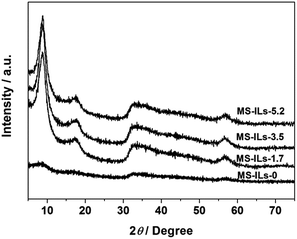 | ||
| Fig. 3 XRD pattern of MoS2 samples prepared by adding different dosages of ionic liquids. X in MS-ILs-X means the mole ratio of ionic liquids and Mo atom. | ||
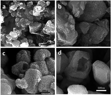
SEM images of MoS2 samples synthesized by adding different IL dosages are shown in Fig. 4a–d. It can be seen from Fig. 4a that MoS2 sample prepared without IL consists of irregular particles which aggregate seriously. Compared to MS-ILs-0 sample, the dispersion of MS-ILs-1.7 sample becomes better and the sizes of the particles become more uniform (Fig. 4b). When the mole ratio of IL and Mo atom increases to 3.5, a few single-shell hollow cages can be observed while most of the particles are still irregular (Fig. 4c). Finally, MoS2 hierarchical polyhedral cages can be obtained by increasing the mole ratio of IL and Mo atom to 5.2. By comparing the morphology of MoS2 samples synthesized by adding different dosages of IL, we speculate that ILs serve as structure-directing agent in the formation of MoS2 double-shell polyhedral cages.
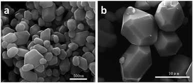
SEM images of precursor PMA-IL (Fig. 5a and b) display the well-defined hollow polyhedron morphology with smooth surfaces. The side length of polyhedrons is 0.5–1.5 μm, which is similar to that of final MoS2 product. The shape and size of the intermediate MS-t-3 remain the same with that of PMA-ILs hybrid while the surfaces of the polyhedron become rather rough (Fig. 5c). Besides, double-shell structure can be found from the SEM image of broken particle (Fig. 5d), which is the same with that observed from TEM image in Fig. 2c.
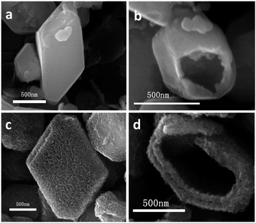 | ||
| Fig. 5 SEM images of time-dependent experiments products at different time: (a and b) 1 h and (c and d) 3 h. | ||
The sulfur content of samples synthesized by different crystallization time was tested by CHNS elemental analysis. It turns out that the precursor MS-t-1 contains 5.32 wt% of sulfur. Since only small amounts of sulfur were detected, we speculate that MS-t-1 contains a small number of sulfur-contained intermediate while the major component is organic–inorganic hybrid PMA-ILs. When the hydrothermal reaction proceeds to 3 h, the mass fraction of sulfur is 24.84%. The significantly increase of sulphur content indicates the formation of sulfur-contained intermediate. With the reaction time further prolongs to 6 h, 12 h, 18 h and 24 h, the sulphur content increases to 25.25, 29.10, 32.18 and 33.72 wt%, respectively. The gradual increase of sulphur content in samples may results from the participation of some dispersive sulfur ions in the oxidation–reduction reaction, which leads to the final formation of MoS2.
Other sulfur sources such as thiourea, thioacetamide and elemental sulfur were adopted instead of GSH while other reaction conditions remained the same. SEM images in Fig. S4† show that all the three common sulfur sources are unable to retain the polyhedral morphology of PMA-ILs organic–inorganic hybrid. To sum up, GSH plays an important role in the formation of MoS2 double-shell polyhedral cages and prevents the growth of PMA-ILs organic–inorganic hybrid into big crystals.
3.3 The possible growth mechanism of MoS2 double-shell polyhedral cages
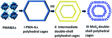
Based on the above discussion of ionic liquid dosage, crystallization time and sulfur source, we speculate that the growth mechanism of MoS2 hierarchical polyhedral cages is as follows. First of all, Mo3O102− anion of PMA and [EMIM]+ cation of ILs bind together due to the electrostatic interaction, generating PMA-ILs organic–inorganic hybrid, which is schematic as Scheme 1. PMA has a typical “Keggin” structure, in which P5+ serves as central ion and four Mo3O102− anions surround P5+ as ligands. Each Mo3O102− ligand contains three Mo–O tetrahedrons, which connect with each other through the corners and edges. Recently, Gao and co-workers proposed that the anisotropic molybdate anions are the main reason for oriented growth of MoOx-based organic–inorganic hybrid nanostructures.35 Thus the tetrahedral building blocks of PMA provide the possibility of synthesizing polyhedral MoS2 materials. In our experiments, [EMIM]+ cations of ILs are considered as structure-directing agents and adsorbed on some planes of Mo–O tetrahedrons, resulting in the formation of polyhedral PMA-ILs hybrid. Meanwhile, the peptide chains of GSH are uniformly dispersed in the solution and form steric hindrance effect, hindering the agglomeration and growing up of PMA-ILs hybrid.For the second step, PMA-ILs hybrid reacts with HS- of GSH, which are located at the inside and outside of the polyhedral shell, to generate sulfur-contained intermediate (Scheme 1-II). The tiny gap in the middle of intermedite shell (Fig. 5d) is probably due to the different diffusion rates of PMA-ILs hybrid and GSH. That is to say, the PMA-ILs hybrid diffuses into the solution in a faster rate than that of GSH movement from solution to the surface of polyhedral shell. As a result, the polyhedral shell of PMA-ILs hybrid disappears, and two new polyhedral shells of intermediate form on both sides of the original shell. This process is similar to Kirkendall effect reported by Xie and co-workers.29 During this process, PMA-ILs hybrid serves as sacrifice template. At last, oxidation–reduction between the intermediate and Mo3O102− proceeds at the hydrothermal temperature, and MoS2 hierarchical polyhedral cages are finally formed (Scheme 1-III).
3.4 Catalytic hydrogenation activities of MoS2 double-shell polyhedral cages
Catalytic hydrogenation reactions of anthracene and naphthalene were performed in a slurry-phase reactor to investigate the catalytic activities of MoS2 double-shell polyhedral cages (labelled as MS-PCs). For comparison, commercial MoS2 (MS-Com) and MoS2 nanoparticles (MS-NPs), which were hydrothermal synthesized by PMA and GSH without adding ILs, were also used as hydrogenation catalysts. Besides, the anthracene hydrogenation performance of MoS2 single-shell polyhedral cages MS-ILs-3.5 (Fig. 4c) was also tested.Hydrogenation of anthracene proceeds ring by ring via reversible successive steps.36 First, 9,10-dihydroanthracene (AH2) is generated by hydrogenation of the middle ring of anthracene. As the reaction proceeds, tetrahydro-product (AH4), octahydro-product (AH8), and perhydroanthracene (AH14) appear in sequence. The first-ring hydrogenation reaction of anthracene is most favored kinetically. Thus it's easy to reach a high conversion of anthracene to AH2. However, the hydrogenation rates of subsequent rings tend to become slower. The hydrogenation of the last ring is most difficult. Based on the above analysis, the activity of MoS2 catalysts mainly depends on the selectivity of deeply hydrogenated products (AH8 and AH14).
Conversion and selectivity of anthracene hydrogenation products are displayed in Fig. 7. Conversion of anthracene hydrogenation with MS-NPs and MS-PCs catalysts is 100%, and the conversion for MS-Com is 90.9%. The high conversion is due to the easy transformation from anthracene to AH2, which is mentioned above. Selectivity of hydrogenation products differs greatly for all the catalysts. AH2 was the main product when MS-Com was adopted as catalyst. The selectivity of deeply hydrogenated products AH8 is highest (78.2%) with MS-PCs as catalyst. Besides, 1.38% of fully hydrogenated product AH14 appeared when MS-PCs were adopted as hydrogenation catalyst. As for MS-NPs catalyst, its selectivities of AH8 and AH14 are inferior to those of MS-PCs catalyst. By comparing selectivity of deeply hydrogenated products, we can draw the conclusion that MS-PCs catalyst has the optimal hydrogenation activity, followed by MS-NPs and MS-Com. When using MoS2 single-shell polyhedral cages MS-ILs-3.5 as catalyst, the conversion of anthracene is 99.46% and the selectivity of deeply hydrogenated products AH8 is 69.92%. The catalytic activity of single-shell polyhedral cages is lower than that of double-shell polyhedral cages (Fig. S5†).
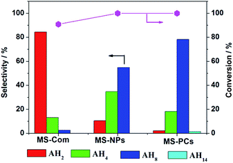 | ||
| Fig. 7 Selectivity and conversion of anthracene hydrogenation reaction using MS-Com, MS-NPs and MS-PCs as catalysts. Reaction conditions: T = 350 °C, PH2 = 8 MPa, t = 4 h, 2.5 wt% cat. | ||
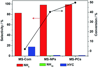 | ||
| Fig. 8 Selectivity and conversion of naphthalene hydrogenation reaction using MS-Com, MS-NPs and MS-PCs as catalysts. Reaction conditions: T = 300 °C, PH2 = 6 MPa, t = 6 h, 2.5 wt% cat. | ||
Tetrahydronaphthalene (NH4) is the main product of naphthalene hydrogenation. The selectivity of decalin (NH10) is very low since the generation of NH10 is thermodynamics restricted. Besides, small amounts of hydrocracking products (HYC) 1,3-dimethyl benzene were detected. The conversion of naphthalene hydrogenation reaction using MS-Com catalyst is very low (2.07%). The conversion with MS-PCs is the highest, followed by MS-NPs (Fig. 8).
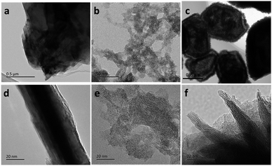
As we all know, the activity of MoS2 catalysts is closely related to its dimension and microstructure. It can be seen from Fig. 9a and d that MS-Com is composed of micro-sized S–Mo–S layers with the stacking layer number of more than a dozen. Fig. 9b and e show that MS-NPs are aggregates of nanosheets with the length of 5–20 nm. In the TEM images of MS-PCs, most of the nanosheets are perpendicular to the double shells of MoS2 polyhedral cages, exposing abundant active edge sites (Fig. 9c and f).
The BET specific surface areas of MS-Com, MS-NPs and MS-PCs were measured N2 physisorption. It turns out that MS-NPs have the largest specific surface areas, followed by MS-PCs and MS-Com. It can be concluded that the hydrogenation activity of MoS2 catalysts doesn't depend on the surface area. This is similar to the results reported by Ramos et al.37 This result is because most of the surface areas result from the basal planes of MoS2 nanosheets, which are catalytic inert.
According to “Rim-edge” model proposed by M. Daage and R. R. Chianelli, active sites of MoS2 for hydrogenation are rim sites which located at the top and bottom layers.18 Due to its much smaller size, MS-NPs have much more rim sites than MS-Com. However, the seriously agglomeration of nanosheets in MS-NPs (Fig. 9b and e) hampers the exposure of rim sites, thus exhibits poor hydrogenation performance. This problem is greatly alleviated in the case of MS-PCs since the vertical-alignment of nanosheets in the polyhedral shell ensures the exposure of abundant rim sites. Moreover, the hollow double-shell structure reduces the density of catalyst and greatly increases the contact areas between reactant molecules and catalysts. In consequence, the as-synthesized MoS2 double-shell polyhedral cages are highly active for catalytic hydrogenation of anthracene and naphthalene. The SEM images of MS-Com, MS-NPs and MS-PCs after anthracene hydrogenation reaction were displayed in Fig. S6,† showing no obvious change of morphology. Thus the structural stability of as-synthesized MoS2 sample was very well.
4. Conclusions
MoS2 double-shell polyhedral cages with lateral length of 0.5–1.5 μm and average shell thickness of 150 nm have been successfully synthesized via an ionic liquid assisted hydrothermal route. The growth mechanism of MoS2 double-shell polyhedral cages is speculated by discussing the synthesis parameters including ionic liquid dosage, crystallization time and sulfur source in detail. It's believed that the anisotropy of Mo3O102− in phosphomolybdic acid and structure-directing effect of ionic liquids [EMIM] Br lead to the formation of organic–inorganic hybrid PMA-ILs polyhedral cages. Afterwards, the hybrid serves as sacrifice template and interacts with glutathione to generate intermediate. Further oxidation–reduction between the intermediate and Mo3O102− produces MoS2 double-shell polyhedral cages. Furthermore, the catalytic property of MoS2 hierarchical polyhedral cages for anthracene and naphthalene hydrogenation is superior to MoS2 nanoparticles and commercial bulk MoS2. The hollow structure and the vertical-alignment of nanosheets in the polyhedral shell are the main reasons for the enhancing catalytic hydrogenation activities of MoS2 double-shell polyhedral cages. Significantly, the strategy of synthesizing MoS2 double-shell polyhedral cages here provides new route to design novel nanostructures of other transition metal sulfides.Acknowledgements
This work was financially supported by the Strategic Priority Research Program of the Chinese Academy of Sciences (Grant No. XDA07020300) and the National Natural Science Foundation of China (Grant No. 21303186).Notes and references
- S. E. Skrabalak and K. S. Suslick, J. Am. Chem. Soc., 2005, 127, 9990–9991 CrossRef CAS PubMed.
- M. Chhowalla, H. S. Shin, G. Eda, L.-J. Li, K. P. Loh and H. Zhang, Nat. Chem., 2013, 5, 263 CrossRef PubMed.
- Y. Lu, X. Yao, J. Yin, G. Peng, P. Cuia and X. Xu, RSC Adv., 2015, 5, 7938 RSC.
- X.-J. Lv, G.-W. She, S.-X. Zhou and Y.-M. Li, RSC Adv., 2013, 3, 21231 RSC.
- J. Xie, H. Zhang, S. Li, R. Wang, X. Sun, M. Zhou, J. Zhou, X. W. Lou and Y. Xie, Adv. Mater., 2013, 25, 5807–5813 CrossRef CAS PubMed.
- J. Chen, N. Kuriyama, H. Yuan, H. T. Takeshita and T. Sakai, J. Am. Chem. Soc., 2001, 123, 11813–11814 CrossRef CAS PubMed.
- R. R. Chianelli, G. Berhault and B. Torres, Catal. Today, 2009, 147, 275–286 CrossRef CAS.
- L. P. Hansen, Q. M. Ramasse, C. Kisielowski, M. Brorson, E. Johnson, H. Topsoe and S. Helveg, Angew. Chem., 2011, 50, 10153–10156 CrossRef CAS PubMed.
- G. Bellussi, G. Rispoli, A. Landoni, R. Millini, D. Molinari, E. Montanari, D. Moscotti and P. Pollesel, J. Catal., 2013, 308, 189–200 CrossRef CAS.
- W. Lai, Z. Chen, J. Zhu, L. Yang, J. Zheng, X. Yi and W. Fang, Nanoscale, 2016, 8, 3823–3833 RSC.
- M. A. Ali, T. Tatsumi and T. Masuda, Appl. Catal., A, 2002, 233, 77–90 CrossRef CAS.
- G. M. Dhar, G. M. Kumaran, M. Kumar, K. S. Rawat, L. D. Sharma, B. D. Raju and K. S. R. Rao, Catal. Today, 2005, 99, 309–314 CrossRef CAS.
- C. Leyva, J. Ancheyta, A. Travert, F. Maugé, L. Mariey, J. Ramírez and M. S. Rana, Appl. Catal., A, 2012, 425–426, 1–12 CrossRef CAS.
- J. G. Speight, Catal. Today, 2004, 98, 55–60 CrossRef CAS.
- B. Scheffer, M. A. v. Koten, K. V. Robschlager and F. C. d. Boks, Catal. Today, 1998, 43, 217–224 CrossRef CAS.
- C. Nguyen-Huy, H. Kweon, H. Kim, D. K. Kim, D.-W. Kim, S. H. Oh and E. W. Shin, Appl. Catal., A, 2012, 447–448, 186–192 CrossRef CAS.
- S. Zhang, D. Liu, W. Deng and G. Que, Energy Fuels, 2007, 21, 3057 CrossRef CAS.
- M. Daage and R. R. Chianelli, J. Catal., 1994, 149, 414–427 CrossRef CAS.
- J. V. Lauritsen, M. Nyberg, J. K. Nørskov, B. S. Clausen, H. Topsøe, E. Lægsgaard and F. Besenbacher, J. Catal., 2004, 224, 94–106 CrossRef CAS.
- J. Kibsgaard, Z. Chen, B. N. Reinecke and T. F. Jaramillo, Nat. Mater., 2012, 11, 963 CrossRef CAS PubMed.
- L. Zhang, H. B. Wu, Y. Yan, X. Wang and X. W. Lou, Energy Environ. Sci., 2014, 7, 3302 CAS.
- X. W. Lou, L. A. Archer and Z. Yang, Adv. Mater., 2008, 20, 3987–4019 CrossRef CAS.
- X. Lai, J. E. Halpert and D. Wang, Energy Environ. Sci., 2012, 5, 5604–5618 CAS.
- M. Wang, G. Li, H. Xu, Y. Qian and J. Yang, ACS Appl. Mater. Interfaces, 2013, 5, 1003–1008 CAS.
- J. Li, D. Wang, H. Ma, Z. Pan, Y. Jiang, M. Li and Z. Tian, Mater. Lett., 2015, 160, 550–554 CrossRef CAS.
- X. Zuo, K. Chang, J. Zhao, Z. Xie, H. Tang, B. Li and Z. Chang, J. Mater. Chem. A, 2016, 4, 51 CAS.
- B. Guo, K. Yu, H. Li, H. Song, Y. Zhang, X. Lei, H. Fu, Y. Tan and Z. Zhu, ACS Appl. Mater. Interfaces, 2016, 8, 5517–5525 CAS.
- Y. Tan, K. Yu, T. Yang, Q. Zhang, W. Cong, H. Yin, Z. Zhang, Y. Chen and Z. Zhu, J. Mater. Chem. C, 2014, 2, 5422 RSC.
- L. Ye, C. Wu, W. Guo and Y. Xie, Chem. Commun., 2006, 4738–4740 RSC.
- L. Ye, W. Guo, Y. Yang, Y. Du and Y. Xie, Chem. Mater., 2007, 19, 6331–6337 CrossRef CAS.
- C. Lv, J. Wang, Q. Huang, Q. Yang, Z. Huang and C. Z. Advances, RSC Adv., 2016, 6, 75870 RSC.
- W. Qiu, J. Jiao, J. Xia, H. Zhong and L. Chen, RSC Adv., 2014, 4, 50529 RSC.
- J. Xie, J. Zhang, S. Li, F. Grote, X. Zhang, H. Zhang, R. Wang, Y. Lei, B. Pan and Y. Xie, J. Am. Chem. Soc., 2013, 135, 17881–17888 CrossRef CAS PubMed.
- C. Zhang, X. Wang, M. Li, Z. Zhang, Y. Wang, R. Si and F. Wang, Chin. J. Catal., 2016, 37, 1569–1577 CrossRef CAS.
- Q. Gao, S. Wang, H. Fang, J. Weng, Y. Zhang, J. Mao and Y. Tang, J. Mater. Chem., 2012, 22, 4709 RSC.
- A. Stanislaus and B. H. Cooper, Catal. Rev., 1994, 36, 75–123 CAS.
- M. Ramos, G. Berhault, D. A. Ferrer, B. Torres and R. R. Chianelli, Catal. Sci. Technol., 2012, 2, 164–178 CAS.
Footnote |
| † Electronic supplementary information (ESI) available. See DOI: 10.1039/c7ra02482g |
| This journal is © The Royal Society of Chemistry 2017 |

