 Open Access Article
Multidimensional structure and enhancement performance of modified graphene/carbon nanotube assemblies in tribological properties of polyimide nanocomposites†
Yuanshi Xin ,
Tongsheng Li*,
Fanglin Xu and
Mingming Wang
State Key Laboratory of Molecular Engineering of Polymers, Department of Macromolecular Science, Fudan University, Shanghai, 200433, P. R. China. E-mail: lits@fudan.edu.cn; Fax: +86-021-51630401; Tel: +86-021-51630401
First published on 11th April 2017
Abstract
Modified graphene/carbon nanotube (abbreviated GCNT) assemblies were prepared by chemical compounding from amino-functionalized graphene (abbreviated MG) and carboxyl-functionalized multi-walled carbon nanotube (abbreviated MCNT). Diverse hybrid structures, such as graphene-shelled CNT microspheres, graphene/CNT interlayers and CNT-coated graphene nanosheets, have been obtained by adjusting the reaction ratio of the two precursor particles. The as-prepared GCNTs were incorporated into polyimide (PI) matrix to yield GCNT/PI composites by in situ polymerization. The mechanical, thermo-mechanical and tribological properties of GCNT/PI composites were investigated and synergistic effects in terms of lubrication and wear resistance have been acquired. The friction coefficient and wear rate decreased by 29.3% and 75.8%, respectively, with only 0.5 wt% addition of GCNT14 (WMG/WMCNT = 1![[thin space (1/6-em)]](https://www.rsc.org/images/entities/char_2009.gif) :
:![[thin space (1/6-em)]](https://www.rsc.org/images/entities/char_2009.gif) 4), compared to virgin PI. The results indicate that combinational structure of multidimensional assemblies has a great influence on the enhancement performance and tribological mechanism of nanocomposites.
4), compared to virgin PI. The results indicate that combinational structure of multidimensional assemblies has a great influence on the enhancement performance and tribological mechanism of nanocomposites.
1. Introduction
Recently, multi-functional reinforcements for advanced polymer composites have generated soaring scientific interest as the demand for applications in high-performance equipment and extreme environments is experiencing intense growth. Nanoparticles possess a low effective threshold, high surface-to-volume ratios and other unique properties related to their nanometer dimensions;1,2 therefore, many attempts have been undertaken to achieve synergistic effects by incorporating nanoparticles with different characteristics simultaneously into a polymer matrix. However, this strategy would not always work well technically, since it is necessary to surface-modify nanoparticles in advance to improve their compatibility with the matrix and avoid serious aggregation,3,4 while many nanoparticles are chemically inert and for some nanoparticles, their particular properties may get degraded after modification. Currently, an innovative approach solving these problems is developed by forming hybrids from various nanoparticles.5 The direct interactions between nanoparticles are helpful to construct combinational structure, which provides additional advantage of achieving desirable properties and helps the dispersion as one nanoparticle can act as a surfactant to another.6,7 Therefore, manufacturing nanoparticle hybrids with diverse structures is becoming a popular research topic in the field of advanced polymer materials.The reinforcing effect of nanoparticles is distinctly influenced by their geometrical shape.8,9 As an example, zero-dimensional fullerene possesses great micro-hardness and lubricity,10 and one-dimensional carbon nanotube (CNT) has excellent tensile strength and Young's modulus,11 while two-dimensional graphene shows high thermal conductivity and electronic mobility.12 Thus, the combination of nanoparticles with different dimensions becomes the common method to integrate diverse physical and chemical properties.13,14 For graphene-CNT hybrids, various preparation routes have been developed to acquire the multidimensional assemblies, which can be mainly classified into three groups: in situ synthesis, π–π interaction and covalent bonding. With respect to in situ synthesis, Ma et al.15 fabricated graphene/CNT hybrids by γ-ray radiation reduction of graphene oxide (GO) in presence of CNT. Tang et al.16 explored the idea of in situ chemical vapor deposition (CVD) of alternative aligned CNTs and graphene sheets to form freestanding 3D carbon sandwiches. In the case of π–π interaction, Feng et al.17 constructed graphene/CNT nano-sandwiches in N-methyl-2-pyrrolidone solution. Li et al.18 prepared GO/CNT hybrid suspension by mixing GO and carboxylated multi-walled CNT (MWCNT) in deionized water and subsequent self-assembly. Regarding covalent bonding, Hwang et al.19 used chlorinated GO and aminated MWCNT to fabricate GO/CNT hybrid films by hot-pressing. Oh et al.20 utilized p-phenylenediamine to acquire a homogeneous cross-linking between oxidized single-walled CNT (SWCNT) and GO and form a bone-mimetic architecture. The listed researches mainly focus on mechanical and thermo properties of graphene/CNT hybrid enhanced composites, and this strategy has been adopted much more widely in the fields of biomedical, photoelectric and energy materials.21–23
Despite the manifold preparation routes for nanoparticle assembly fabrication, all these methods have different deficiencies. The process of in situ synthesis takes the advantages of precision and stabilization, while that of π–π interaction is the handiest way. However, both of them are faced with the significant insufficient in structure and size control, which is crucial to obtain synergistic effect from the precursor nanoparticles.24,25 Chatterjee et al.26 studied mechanical reinforcement in epoxy matrix with the addition of graphene nanoplatelets with two different dimensions and various mixture ratios of CNTs and found that the combination of high reaction ratio of CNTs and larger surface area of graphene sheets contributes to the synergistic effect. Yang et al.27 prepared cyanogen functionalized CNT and graphene/poly(arylene ether nitrile) nanocomposites and discovered the parabolic trend of mechanical properties with the increasing weight ratio of CNT to graphene. In our previous work,28,29 a comparative study between modified GO/nano-PTFE hybrid and modified GO/nano-MoS2 hybrid revealed that except the intrinsic characteristics of the precursor nanoparticles, the combinational structure of the assemblies also has a significant influence on the enhancement performance in tribological properties.
Compared to the other two methods, covalent bonding between graphene and CNT shows the facility in surface modification and structure design, making the assemblies more compatible with the matrix. However, the combinational structures of graphene/CNT assemblies reported so far are mostly sandwich-like or networked.30–32 As a result, an original attempt to develop diverse structures and compare the enhancement effect is necessary. In addition, although the tribological characteristics of graphene/polymer composites and CNT/polymer composites have got a lot of exploration,33,34 the combined utilization of graphene and CNT in tribological polymer materials is still infrequent. In consideration of the wear resistant quality of graphene and the lubricity of CNT, it can be expected that a synergetic effect could be obtained in graphene/CNT hybrids. However, a related study showed that with the introduction of 0.5 phr MWCNT and 0.5 phr GO into epoxy matrix, the friction coefficient decreased below that of the neat matrix whereas the wear rate increased.35 Such unsatisfactory result can be ascribed to the lack of combinational structure design as well as the poor dispersibility and compatibility of unmodified nanoparticles.
To overcome the disadvantages mentioned above and develop a deeper understanding between the structure and performance of nanoparticle assemblies, we designed and prepared modified graphene/carbon nanotube (abbreviated GCNT) assemblies by chemical compounding from amino-functionalized graphene (abbreviated MG) and carboxyl-functionalized multi-walled carbon nanotube (abbreviated MCNT). The as-prepared GCNTs present diverse combinational structures from graphene-shelled CNT balls to CNT-coated graphene sheets by adjusting the reaction ratio. To examine the enhancement effect, MG, MCNT and GCNTs were incorporated into PI matrix, a high-performance polymer often used for tribological components in automotive and aerospace industry.36 The mechanical, thermo-mechanical and tribological properties were investigated and the close connection between the structure of GCNT and the corresponding tribological mechanism is demonstrated as well.
2. Experimental
2.1 Materials
Expandable graphite powders (99.5%, Yingtai Co., Yangtai, China), amino multi-walled carbon nanotubes (95%, 0.45 wt% amino content, 8–15 nm in outside diameter, ∼50 μm in length, Chengdu Organic Chemicals Co. Ltd., Chengdu, China) and bisphenol-A dianhydride (BPADA, 99%, Shanghai Research Institute of Synthetic Resins, Shanghai, China) were selected and supplied. 4,4′-Diphenylmethane diisocyanate (MDI), 2-(4-aminophenyl) ethanol, 4-aminobenzoic acid (PABA), isopentyl nitrite, 1-ethyl-3-(3-dimethylaminopropyl) carbodiimide hydrochloride (EDC·HCl) and 1-hydroxybenzotriazole (HOBT) were provided (98%, 98%, 99%, 90%, 98.5% and 99%, respectively, Aladdin reagent Co., Shanghai, China). 4,4′-Oxydianiline (ODA), triethylamine (TEA) and N,N-dimethylformamide (DMF) were acquired (98%, 99.5% and 99.5%, respectively, Sinopharm Group Chemical Reagent Co. Ltd., Shanghai, China).2.2 Preparation of GCNT
Amino-functionalized graphene (MG) was prepared by grafting small molecule segments containing amino groups onto a chemically reduced graphene oxide (rGO) surface. The detailed preparation process can be found in our published work.33To modify CNT, 50 mg CNT was dispersed in 100 ml DMF with sonication at room temperature for 1 h. 2.5 g PABA and 1.5 ml isopentyl nitrite were added to the above suspension, and the mixture was mechanically stirred at 90 °C for 6 h, and then filtrated with a 0.2 μm Teflon filter film. To remove unreacted molecules, the collected powders were washed with DMF and deionized water until the filtrate was clear. The resulting solids were vacuum-dried overnight at 70 °C, yielding carboxyl-functionalized CNT (MCNT).
The procedure for chemical compounding between MG and MCNT can be described as follows: 25 mg MG and 25 mg MCNT were re-dispersed in 100 ml DMF with sonication for 6 h. 0.65 g EDC·HCl, 0.46 g HOBT and 5 ml TEA were added to the above suspension, and the mixture was vigorously stirred at 40 °C for 24 h under nitrogen. Powders obtained from the matrix by vacuum filtration were rinsed with DMF and deionized water. Finally, the solids were dried at 70 °C under vacuum overnight, yielding GCNT11 (WMG/WMCNT = 1![[thin space (1/6-em)]](https://www.rsc.org/images/entities/char_2009.gif) :
:![[thin space (1/6-em)]](https://www.rsc.org/images/entities/char_2009.gif) 1). GCNT41 (WMG/WMCNT = 4
1). GCNT41 (WMG/WMCNT = 4![[thin space (1/6-em)]](https://www.rsc.org/images/entities/char_2009.gif) :
:![[thin space (1/6-em)]](https://www.rsc.org/images/entities/char_2009.gif) 1) and GCNT14 (WMG/WMCNT = 1
1) and GCNT14 (WMG/WMCNT = 1![[thin space (1/6-em)]](https://www.rsc.org/images/entities/char_2009.gif) :
:![[thin space (1/6-em)]](https://www.rsc.org/images/entities/char_2009.gif) 4) assemblies were also prepared using the above method with the reaction ratio changed.
4) assemblies were also prepared using the above method with the reaction ratio changed.
2.3 Fabrication of GCNT/PI composites
To investigate the enhancement performance of GCNTs, GCNT/PI specimens were prepared and the selected additive loading was constant as 0.5 wt%, according to our previous work.28,29 In a typical operation, 40 mg GCNT (GCNT41, GCNT11 or GCNT14) was re-dispersed in 32 g DMF with sonication for 2 h, and then 2.19 g ODA and 5.81 g BPADA were added to the above suspension. The mixture was stirred vigorously at room temperature for 24 h under nitrogen, yielding GCNT/polyamide acid (GCNT/PAA) solution. The film specimens and coating specimens were prepared by casting GCNT/PAA solutions onto glass substrates or stainless steel plates, respectively.33 The specimens were then placed in a vacuum oven at room temperature to remove air bubbles and heated at 70 °C for 2 h and 100, 150, 200 and 300 °C each for 1 h to completely get rid of volatile and achieve thermal imidization. The thickness of film and coating was ∼50 μm. For comparison, virgin PI, MG/PI (PI composite containing 0.5 wt% of MG) and MCNT/PI (PI composite containing 0.5 wt% of MCNT) specimens were fabricated in the same manner.2.4 Friction and wear tests
Tribological tests were performed on a reciprocating friction and wear testing machine (HS-2M, Lanzhou Zhongke Kaihua Technology Development Co., Ltd.). The contact schematic diagram of the frictional couple is provided (Fig. S1†). The roughness of the stainless ball used is ∼20 nm and the diameter is 6 cm. The test was performed at temperature: 20 ± 2 °C, relative humidity: 40%, applied load: 10 N, reciprocating frequency: 10 Hz. The length of stroke in one cycle is 5 mm. Each test was carried out for 10 min. The friction coefficient was obtained by the testing machine automatically. The depth of the wear scar was measured using a stylus surface profiler (Dektak 150, Veeco Instruments Inc.), and the wear volume (ΔV, mm3) of the specimen was calculated according to the following equation:
 | (1) |
 | (2) |
2.5 Characterization
Fourier transform infrared (FTIR) spectra were collected using a Nicolet Nexus 470 spectrometer. Raman spectra were recorded on a Horiba JobinYvon XploRA spectrometer with 638 nm laser excitation. X-ray diffraction (XRD) patterns were acquired by a Bruker D8 Advance diffractometer using Cu Kα radiation (λ = 0.154 nm) at an accelerating voltage of 40 kV and a current of 40 mA. Thermogravimetric analysis (TGA) were carried out with a Mettler Toledo Thermo Gravimetric Analyzer under nitrogen flow at a heating rate of 20 °C min−1. Field emission scanning electron microscopy (FESEM) images were carried out by a Zeiss Ultra 55 FESEM to observe the structure of nanoparticles and the fracture surface of PI composites. Size distribution of GCNT hybrids was measured through dynamic light scattering (DLS) on a Malvern Instruments Nano ZS90 Analyzer. Mechanical properties were evaluated by a universal testing machine (CMT-4102, Sans Co., China) at a stretched speed of 5 mm min−1 with 20 °C and 40% relatively humidity, using dumbbell-type specimens, according to ISO 527-3:1995 standard. Dynamic mechanical analysis (DMA) were performed on a Mettler Toledo DMA/SDTA861e Analyzer. Each specimen was tested under tension mode from 100 to 300 °C at a heating rate of 5 °C min−1 and a frequency of 1 Hz, selected strain amplitude being set to 0.3%, and static compressive stress of 0.5 N. Data reported here represents the average of five tests. Scanning electron microscopy (SEM) images were observed on a Tescan VEGA 3 XMU SEM.3. Results and discussion
3.1 Preparation and characterization of GCNT
Fig. 1 illustrates the fabrication process of GCNT which includes three steps: (a) grafting small molecule segments containing amino groups onto a chemically reduced graphene oxide surface, (b) chemical modification of CNT with PABA and (c) preparation of GCNT by amidation reaction between MG and MCNT.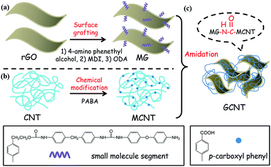 | ||
| Fig. 1 Covalent combination between rGO and CNT including (a) surface grafting of rGO, (b) chemical modification of CNT and (c) preparation of GCNT by amidation reaction between MG and MCNT. | ||
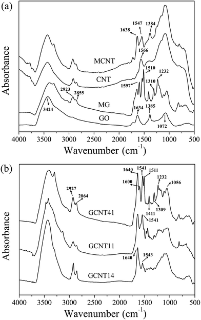
To characterize the chemical composition of the resulting nanoparticles, several analysis methods such as FTIR, Raman spectra, XRD and TGA were applied. Fig. 2a gives the comparison of FTIR spectra between GO, MG, CNT and MCNT. The characteristic bands at 3424, 1634, 1385 and 1072 cm−1 for GO correspond to O–H stretching vibration, C![[double bond, length as m-dash]](https://www.rsc.org/images/entities/char_e001.gif) O stretching vibration, O–H in-plane bending vibration and C–O stretching vibration, respectively. After grafting, several new absorptions for MG arise from the introduction of phenyl ethanol groups and amino groups. For example, the doublet at 2923 and 2855 cm−1 belongs to C–H asymmetric stretch of methylene groups and the bands at 1597, 1510, 1310 and 1232 cm−1 are assigned to phenyl skeleton stretching vibration, N–H in-plane bending vibration, C–N stretching vibration and C–O–C stretching vibration, respectively. These changes indicate that small molecule segments containing amino groups were effectively grafted onto GO surface. Detailed proof of successful chemical modification of MG can been found in our previous work.33 Besides, regarding the diazonium addition between PABA and CNT, the band at 1566 cm−1 for N–H in-plane bending vibration (regarding that CNT used here contains amino groups as raw material) disappears in the spectra for MCNT, whereas new absorptions at 1638 cm−1 (C
O stretching vibration, O–H in-plane bending vibration and C–O stretching vibration, respectively. After grafting, several new absorptions for MG arise from the introduction of phenyl ethanol groups and amino groups. For example, the doublet at 2923 and 2855 cm−1 belongs to C–H asymmetric stretch of methylene groups and the bands at 1597, 1510, 1310 and 1232 cm−1 are assigned to phenyl skeleton stretching vibration, N–H in-plane bending vibration, C–N stretching vibration and C–O–C stretching vibration, respectively. These changes indicate that small molecule segments containing amino groups were effectively grafted onto GO surface. Detailed proof of successful chemical modification of MG can been found in our previous work.33 Besides, regarding the diazonium addition between PABA and CNT, the band at 1566 cm−1 for N–H in-plane bending vibration (regarding that CNT used here contains amino groups as raw material) disappears in the spectra for MCNT, whereas new absorptions at 1638 cm−1 (C![[double bond, length as m-dash]](https://www.rsc.org/images/entities/char_e001.gif) O stretching vibration), 1547 cm−1 (phenyl skeleton stretching vibration) and 1384 cm−1 (O–H in-plane bending vibration) appear, manifesting that carboxyl-functionalized CNT has been successfully prepared.
O stretching vibration), 1547 cm−1 (phenyl skeleton stretching vibration) and 1384 cm−1 (O–H in-plane bending vibration) appear, manifesting that carboxyl-functionalized CNT has been successfully prepared.
An in-depth study of the chemical distinctions between GCNT assemblies with different reaction ratios is significant to understand the diverse structures of these particles. Fig. 2b shows the FTIR spectra for GCNT41, GCNT11 and GCNT14. The characteristic bands for GCNT41 are roughly coincident with those for MG and MCNT, such as the absorptions at 1640 cm−1 (C![[double bond, length as m-dash]](https://www.rsc.org/images/entities/char_e001.gif) O stretching vibration from MCNT), 1541 cm−1 (phenyl skeleton stretching vibration from MCNT), 1511 cm−1 (N–H in-plane bending vibration from MG), 1411 cm−1 (O–H in-plane bending vibration from MCNT) and 1309 cm−1 (C–N stretching vibration from MG). However, with the reaction ratio of MG to MCNT declining, the intensity of the bands at 1511 and 1411 cm−1 decreases in the spectra for GCNT11, and these two bands are almost imperceptible for GCNT14, indicating that the extent of amidation reaction got improved. Besides, an obvious doublet exists around 3300 cm−1 (N–H stretching vibrations for amino group) in the spectra for GCNT41, while the feature of doublet weakens for GCNT11 and even disappears for GCNT14 (the singlet around 3400 cm−1 representing the N–H stretching vibration for amide bonds), further illustrating the differences in amidation reaction extent. As the notable steric hindrance effect of MG could decrease the contact probability of the reactive groups with MCNT, the raised amount of MCNT helps expand the interlayer distance of graphene sheets and thus excite the reaction activity, which will be further discussed hereinafter.
O stretching vibration from MCNT), 1541 cm−1 (phenyl skeleton stretching vibration from MCNT), 1511 cm−1 (N–H in-plane bending vibration from MG), 1411 cm−1 (O–H in-plane bending vibration from MCNT) and 1309 cm−1 (C–N stretching vibration from MG). However, with the reaction ratio of MG to MCNT declining, the intensity of the bands at 1511 and 1411 cm−1 decreases in the spectra for GCNT11, and these two bands are almost imperceptible for GCNT14, indicating that the extent of amidation reaction got improved. Besides, an obvious doublet exists around 3300 cm−1 (N–H stretching vibrations for amino group) in the spectra for GCNT41, while the feature of doublet weakens for GCNT11 and even disappears for GCNT14 (the singlet around 3400 cm−1 representing the N–H stretching vibration for amide bonds), further illustrating the differences in amidation reaction extent. As the notable steric hindrance effect of MG could decrease the contact probability of the reactive groups with MCNT, the raised amount of MCNT helps expand the interlayer distance of graphene sheets and thus excite the reaction activity, which will be further discussed hereinafter.
Raman spectrum analysis was conducted to examine the structural parameters of these as-prepared particles, as shown in Fig. S2.† As know, the intensity ratio of D band to G band in the Raman spectra of carbon-based nano-materials represents the graphitization degree, which has a great influence on their performance as additives. The ID/IG value of GCNT11 (1.48) is higher than that of MG (1.36) and MCNT (1.33), demonstrating that GCNT assemblies contain more lattice defects than these two precursor particles.37 In addition, the location of G band moves to a lower frequency position when MG and MCNT incorporated into GCNT. As the higher frequency of G band corresponds to the less number of graphene layers, this result further confirms that MCNT has been immobilized onto MG surface.38
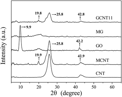
Detailed crystal structures of nanoparticles were manifested in XRD patterns, as presented in Fig. 3. The XRD pattern for CNT exhibits an obvious diffraction peak at 25.8°, corresponding to an inner-walls distance of 0.36 nm. After modification with PABA, some new peaks with weak intensity appear in the pattern for MCNT, among which the peak at 19.9° (consistent with an interlayer spacing of 0.45 nm) is relatively more obvious. This indicates that the outer layer of CNT may split open during the diazonium addition reaction, resulting the lattice defects as revealed by Raman spectra. Besides, a sharp diffraction peak at 9.9° (corresponding to an interlayer spacing of 0.90 nm) exists in the pattern for GO,20 while after grafting, no obvious peak shows on the XRD trace of MG, suggesting the stacking of MG is disordered.39 Furthermore, the XRD pattern for GCNT11 is basically the same as MCNT, which means that MCNT is distributed on the surface of MG and no significant stacking of MG occurs.
In order to explore the combinational architecture of the GCNT assemblies, we obtained the FESEM images of these nanoparticles (Fig. 4). The average lateral dimension of MG is ∼500 nm, as reported in our previous work33 and some aggregation can be observed in bulk status, according to Fig. 4a. The MCNTs have a diameter of ∼20 nm and formed a web-like tangle due to the long length and π–π interaction, as shown in Fig. 4b. Regarding the dimensional differences between MG and MCNT, the GCNT assemblies may possess diverse structures with the changed reaction ratio and fortunately such meaningful phenomenon has been observed in this work. GCNT41 particles present the hybrid architecture as graphene-shelled CNT microspheres (Fig. 4c and d), because each MCNT fiber is likely to react with more than one graphene sheets and the connected platelets wrapped around the clew of MCNTs to form the stable structure. With the reaction ratio of MG to MCNT going down, graphene sheets have the increased opportunity to be covered by MCNTs through surface grafting thus get separated from each other. As expected, GCNT11 particles show the graphene/CNT multilayer sandwich-like structure (Fig. 4e and f), while GCNT14 particles have the appearance as CNT-coated few-layer graphene nanosheets (Fig. 4g and h). Furthermore, the size distribution by number of these three hybrid particles was measured by dynamic light scattering, as shown in Fig. S3,† and the average sizes of GCNT41, GCNT11 and GCNT14 are about 650, 1100 and 220 nm, respectively. The remarkable reduction in particle size of GCNT14 indicates that an appropriate content of MCNT in GCNT hybrid can prevent the restacking of MG and consequently contributes the homogeneous dispersion in polymer matrix (isolation effect of MCNT). The properties of polymer nanocomposites depend strongly on the size and shape of additives, so such great difference in geometry of GCNT assemblies would contribute to the varying enhancement performance discovered in this work.
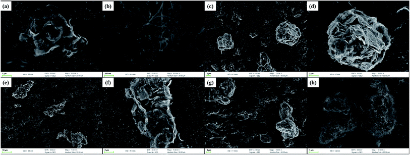 | ||
| Fig. 4 FESEM images of nanoparticles: (a) MG, (b) MCNT, (c) and (d) GCNT41, (e) and (f) GCNT11 and (g) and (h) GCNT14. | ||
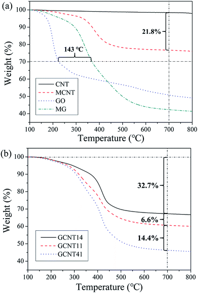
To evaluate the extent of chemical modification and the thermostability of the as-prepared nanoparticles, TGA measurements were conducted with the results presented in Fig. 5. Compared to CNT, 21.8 wt% content of p-carboxyl phenyl (a grafting density of 1 COOH per 42 carbon atoms) is observed in MCNT after diazonium addition, which furnishes a mass of reactive sites for further reaction with MG. In addition, a high grafting density of 1 NH2 per 34 carbon atoms was achieved in the grafting process of MG (demonstrated in our previous work33). Furthermore, the grafted small molecular segments are more thermotolerant than the initial oxygen-containing groups formed in the hydrothermal process, because the 30% weight-loss temperature of MG is 143 °C higher than that of GO. The sufficient modification degree and high thermostability of grafted functional groups would benefit the further incorporation of MCNT with MG and improve the interfacial compatibility with polymer matrix.
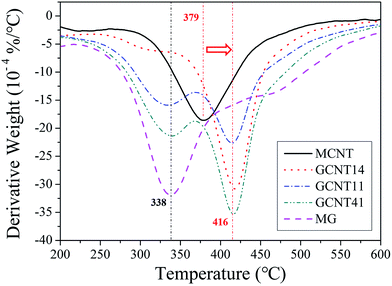
GCNT assemblies with different reaction ratios possess diverse thermostability (Fig. 5b), GCNT41 with the higher MG content shows the larger weight loss at high temperature compared to GCNT11 and GCNT14. Subtle variations of thermal behaviors of these nanoparticles can be distinguished through the derivative TG (DTG) plots (Fig. 6). Two major mass-loss peaks of GCNTs can be observed: the peak at approximately 338 °C results from the decomposition of MG, and the peak at 416 °C from MCNT. Noting that the original mass-loss peak temperature of MCNT is 379 °C, the elevation of the decomposition temperature indicates that the thermostability of amide bonds got improved when carboxyl groups of MCNT reacted with the amino groups on MG.40 Therefore, the mass-loss ratio at 379 °C can represent the amount of unreacted amino groups in GCNT hybrids. The mass-loss ratio of GCNT41 at 379 °C is much greater compared to GCNT11 and GCNT14, consistent with the result of FTIR spectra, which indicates the poor reaction extent of amidation in GCNT41. The special combinational structure of GCNT41 has a great influence on the reaction process: MCNT clews in GCNT41 were cladded by MG sheets, and only a few of MCNTs assembled outside the hybrid balls, as presented in Fig. 4d, so most of the MCNT fibers in the inner of clew did not have the access to contact with MG. Besides, it is also noteworthy that in the case of GCNT14, the peak at 338 °C is almost absent in the DTG plot, further illustrating that the amino groups have completely reacted with the carboxyl groups. As shown in Fig. 4h, the surfaces of GCNT14 sheets have been wholly covered by MCNTs with amide bonds. This structure is critical to fulfill the optimal synergistic effect of graphene and CNT, which will be discussed later.
3.2 Reinforcing effect of GCNT
Mechanical and thermodynamic properties of nanocomposites have a great influence on the tribological behavior,41,42 so comparative analysis of these properties is necessary to understand the tribological mechanism. Fig. 7 shows the relationships between mechanical properties and different additives of PI composites. GCNT11/PI and GCNT14/PI composites possess enhanced tensile strength and elongation at break compared to virgin PI and MG/PI, while the mechanical properties of GCNT41 present varying degrees of degradation, indicating that the structure as graphene-shelled CNT microsphere of GCNT41 is comparatively unhelpful to provide reinforcing effect. As revealed in our previous work,33 an oriented distribution of MG in PI matrix was observed and MG sheets aligned parallel to the film surface can effectively transmit tensile stress, avoiding the formation of stress concentrative point. While in the case of GCNT41/PI, the poor compatibility with matrix, as shown in Fig. 8d, caused some stress points around the hybrid particles, resulting in the reduction of mechanical properties.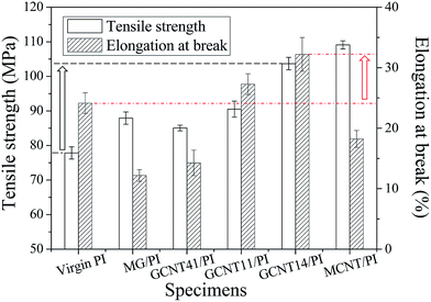 | ||
| Fig. 7 Tensile strength and elongation at break of virgin PI, MG/PI, GCNT41/PI, GCNT11/PI, GCNT14/PI and MCNT/PI specimens. | ||
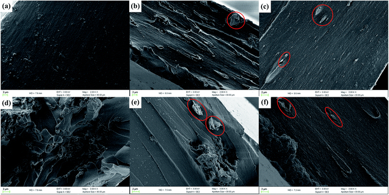 | ||
| Fig. 8 FESEM images showing fracture surfaces of (a) virgin PI, (b) MG/PI, (c) MCNT/PI, (d) GCNT41/PI, (e) GCNT11/PI and (f) GCNT14/PI. | ||
Because of the unavoidable aggregation of nanoparticles and the consequent poor interfacial interaction, the elongation at break of MG/PI and MCNT/PI as well as GCNT41/PI is lower than that of virgin PI. However, GCNT11/PI and GCNT14/PI specimens show improved ductility with the better elongation at break compared to virgin PI, which means moderate content of MG in GCNT hybrids helps separate the tangled MCNT clews, and immobilized MCNTs could in turn improve the mechanical interlocking of MG with the matrix. Sun et al.43–45 manifested that CNTs can get disentangled with exfoliated ZrP nanoplatelets using a nanoplatelet-assisted dispersion approach, and it is credible to speculate that MG exerted a similar influence in adjusting the aggregation state of MCNT, since MG sheets possess the analogous flake shape with ZrP and the mixture solution of MG and MCNT was ultrasonic treated for hours before reaction. As a result, GCNT14/PI composite shows the best mechanical properties in this study, with the tensile strength and elongation at break increase by 33.3% and 33.6%, respectively, compared to virgin PI, demonstrating the synergistic effect of MG and MCNT.
As know, the mechanisms of strengthening effect of nanoparticles are closely related to the interfacial interaction and microstructure between nanoparticles and polymer matrix, such as mechanical interlocking, nucleating effect and networked connection, as well as the dispersion and compatibility of nanoparticles in the matrix.46,47 Therefore, FESEM images of fracture surfaces were obtained to give a visualized evaluation of the compatibility of the additives. As shown in Fig. 8a and c, the fracture surfaces of virgin PI and MCNT/PI specimens are relatively smooth and only a few MCNT fibers exposed the ends out of the matrix during the tensile fracture process, while obvious gullies with partly bare MG sheets exist on the facture surface of MG/PI specimens and some MG sheets even got pulled out of the matrix (Fig. 8b). These results manifest that the interfacial compatibility of MCNT is much better than that of MG, corresponding to the changes in mechanical properties. In addition, the fracture surfaces of GCNT41/PI, GCNT11/PI and GCNT14/PI exhibit quite different figures. Many irregular hollows appear on the fracture surface of GCNT41/PI (Fig. 8d), and some half-open as well as intact graphene-CNT balls can be found outside the matrix (Fig. S4†), indicating the poor compatibility of GCNT41 and the heterogeneous internal structure. In spite of some minor aggregation of GCNT11 particles, the fracture surface of GCNT11/PI is much smoother than that of GCNT41/PI, while still some graphene-CNT sandwiches were peeled off from the matrix (Fig. 8e). Comparatively, GCNT14/PI specimen shows a flat appearance without significant aggregation, and GCNT14 sheets embedded tightly in the matrix (Fig. 8f). As discussed in our previous work,28,29 surface modification of graphene and the CNT-coated few-layer structure of GCNT14 contribute to the construction of strong interfacial layer, where mechanical unlocking can occur during the stretching process due to disentanglement of grafted CNT chains, thus improving the ductility of GCNT14/PI composite.
Thermo-mechanical properties are especially critical for wear-resistant materials, as the friction heat would cause a rapid rise of temperature on the worn surface during the high-speed friction process. Temperature dependence of activation energy for relaxation, as well as the damping spectra allow us to get more detailed information about the movements of polymer chains,48 so DMA experiments were conducted to further explore the reinforcing mechanism and the interfacial feature. Fig. 9a shows the storage modulus of virgin PI and PI composites as a function of temperature. MCNT/PI composite possesses the highest storage modulus below 180 °C, about 40% greater compared to virgin PI, while the storage modulus of MG/PI is relatively lower, but still greater than that of virgin PI (Fig. S5†). An interesting discovery is that GCNT41/PI and GCNT11/PI composites possess reduced storage modulus; however, GCNT14/PI composite has the value of storage modulus between MCNT/PI and MG/PI. Regarding the difference in geometry appearance of these GCNT assemblies, this result indicates that superfluous content of MG in GCNT facilitates the incorporation of large-scale particles which impairs the interfacial compatibility and heat transmission, and thus damages the thermo-mechanical performance of GCNT41 and GCNT11. On the contrary, the storage modulus of GCNT14/PI specimen is 33% greater than that of virgin PI at 150 °C, and more significantly, 2-fold greater at 200 °C (Fig. S5†). Furthermore, the storage modulus of GCNT14/PI at 200 °C is even greater compared to MCNT/PI and MG/PI, because of the strong interfacial mechanical interlocking offered by the particular combinational structure, as well as the excellent thermal conductivity (5000 W m−1 K−1) of graphene.49
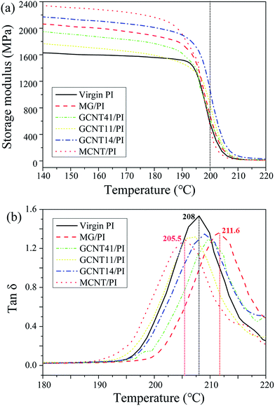 | ||
| Fig. 9 (a) Storage modulus of virgin PI and PI composites as a function of temperature. (b) Damping spectra of virgin PI and PI composites. | ||
Representative damping spectra (tan![[thin space (1/6-em)]](https://www.rsc.org/images/entities/char_2009.gif) δ versus temperature) for virgin PI and PI composites are presented in Fig. 9b. The value of tan
δ versus temperature) for virgin PI and PI composites are presented in Fig. 9b. The value of tan![[thin space (1/6-em)]](https://www.rsc.org/images/entities/char_2009.gif) δ represents the loss modulus to storage modulus ratio, which is closely related to the response of polymer segments to imposed load. Around the Tg region (damping spectra peaks), the tan
δ represents the loss modulus to storage modulus ratio, which is closely related to the response of polymer segments to imposed load. Around the Tg region (damping spectra peaks), the tan![[thin space (1/6-em)]](https://www.rsc.org/images/entities/char_2009.gif) δ values of PI composites are lower compared to virgin PI, as the segment confinement gets enhanced due to immobilization of polymer chains near the particle surface. GCNTs possess much higher stiffness compared to PI matrix, resulting the impairment of damping capacity.
δ values of PI composites are lower compared to virgin PI, as the segment confinement gets enhanced due to immobilization of polymer chains near the particle surface. GCNTs possess much higher stiffness compared to PI matrix, resulting the impairment of damping capacity.
The peak temperature of damping spectra can be regarded as Tg value. The Tg value of MG/PI specimen is higher than that of virgin PI, ascribed to strong covalent adhesion between MG and PI matrix. This result indicates a high grafting efficiency of PI chains on the MG surface, as demonstrated in our previous work.33 However, when compounded with MCNT, the Tg values of GCNT/PI composites declined compared to MG/PI. Such similar phenomenon has also been observed by Lin et al.,32 where polyvinyl alcohol/graphene composites possess the highest Tg value compared to those incorporated with additional MWCNTs. A reasonable interpretation is that the addition of nanoparticles into PI matrix has a two-sided effect on glass–rubber transition. On the one hand, nanoparticles restricted the movements of polymer chains by steric hindrance or mechanical interlocking, while on the other hand, some nanoparticles may be deleterious to the growth of polymer chains or the crosslinking process during in situ polymerization. The latter probably plays the main role in the case of MCNT, as proton exchange could happen between the carboxyl groups on MCNT surface and the anhydride groups of BPADA, which would degrade the imidization reaction and lessen the rigidity of PI chains. Regarding GCNT particles, GCNT41 and GCNT14 show the Tg elevation effect, because MCNTs have been cladded by MG sheets in the case of GCNT41 and the carboxyl groups on MCNT in the case of GCNT14 reacted sufficiently with MG, as discussed in the preceding section. The above-mentioned changes in thermo-mechanical properties of GCNT/PI composites intensely reveal the close connection between the architecture of nanoparticle assemblies and the reinforcing performance of nanocomposites.
3.3 Tribological effect of GCNT
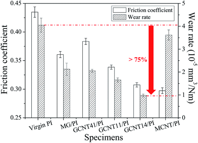
GCNT assemblies derive the characteristics of high mechanical strength from MCNT and interfacial confinement effect from MG, and thus appear to be probable self-lubricating and anti-wear additives for polymer composites. To investigate the tribological performance of GCNTs, friction tests were performed on as-prepared specimens using a reciprocating friction and wear testing machine. As shown in Fig. 10, the friction coefficient and wear rate of GCNT/PI composites exhibit a continuous downward trend with the increasing MCNT content. GCNT14/PI specimen shows the reduction about 29% in friction coefficient and 76% in wear rate compared to virgin PI. Meanwhile, only 17% reduction is obtained in friction coefficient of MG/PI specimen and the enhancement in abrasive resistance of MCNT/PI is negligible. The obviously improved tribological performance indicates that GCNT14 takes the advantage of high wear resistance and lubricating effect, from MG and MCNT, respectively.It is worth mentioning that in the case of GCNT41/PI specimen, the friction coefficient is higher than MG/PI, ascribe to the special combinational structure. As discussed above, most of the MCNT clews have been covered by MG sheets in GCNT41 (Fig. 4c and d), which hinders the lubricating effect of MCNT. In contrast, MG sheets are coated by MCNT or assembled into interlayer structure with MCNT in GCNT14 and GCNT11, making MCNTs easily expose on the worn surface during friction, thus achieving outstanding lubricity. Besides, the few-layer shape of GCNT14 (Fig. 4e and f) is much more analogous to the flake of MG, which is crucial to take advantage of the protective and suppressive effect of MG. As revealed in our previous work,33 MG tends to present an oriented configuration parallel to the film surface, attributed to solvent evaporation induced orientation, casting induced orientation and thickness confinement. On the one hand, the parallelly distributed MG sheets on the worn surface provide direct protection against the normal force/load (protective effect), considering the high modulus (0.25 TPa) and intrinsic strength (125 GPa) of graphene. On the other hand, the tightly packed MG sheets, which possess strong interfacial interaction with the PI matrix, can effectively hinder the desquamation of large-sized wear debris against the tangential force/friction force (suppressive effect), resulting in the enhanced wear resistance.
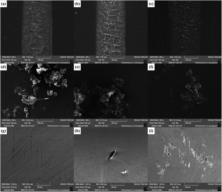
SEM observations of worn surfaces, wear debris and surfaces of coupled parts are helpful to understand the related tribological mechanism. As shown in Fig. S6a and e,† the worn surfaces of virgin PI and MCNT/PI are relatively flat and display signs of adhesive wear, as some inconspicuous embossments exist. However, the worn surface of MG/PI reflects some typical feature of fatigue deformation, such as some compact furrows and shallow cracks (Fig. S6c†). For GCNT/PI specimens, the characteristic of adhesive wear (some embossments on the worn surface) is more evident in GCNT41/PI specimen (Fig. 11a), while the wear type of GCNT11/PI and GCNT14/PI is the typical fatigue wear, noting that the cracks on worn surface have intersected into a network (Fig. 11b and c). The changes in wear type coincide well with the differences in wear rate, as the flat and tough few-layer GCNT14 assemblies on the worn surface can effectively protect the composite from plastic deformation, but the ball-like GCNT41 assemblies do not have such function.
Meanwhile, the wear width of GCNT/PI specimens is narrower (about 200 μm) than that of virgin PI (about 250 μm) (Fig. S6a†), indicating that after the incorporation of GCNT, the real contact area during the friction process got a large reduction, which contributes to the observed decrease in friction coefficient.50 SEM images of wear debris further confirm the changes in wear performance, as shown in Fig. 11 and S6.† After the incorporation of MG and GCNT, the morphology of wear debris transformed from lager pieces into small sheets, while wear debris shape of MCNT/PI specimen is more similar to virgin PI, consistent with the wear type as discussed above. Furthermore, the size of wear debris of GCNT14/PI composite is smallest among these specimens, which can be attributed to the suppressive effect of MG and the enhanced mechanical properties.
To further investigate the tribological effect of GCNTs, SEM images showing surfaces of coupled parts are also presented in Fig. 11. Some slight scratches can be observed on the surface of coupled part for GCNT41/PI composite (Fig. 11g), indicating that the GCNT41 balls possess certain rigidity and got exposed during friction, thus causing the abrasion of the coupled part. Besides, the coupled part surface of GCNT11/PI shows some spots of adhered particles (Fig. 11h), and that of GCNT14/PI has more transferred sheets, forming a discontinuous transfer film (Fig. 11i). The differences in the appearance of coupled part surfaces manifest that the increased content of MCNT contributes to the transfer of GCNT particles from the polymer matrix onto the coupled part (transfer effect of MCNT). Just as explained above, there are only a few MCNT fibers immobilized outside the GCNT41 assemblies, and thus no particle adhered on the coupled part surface of GCNT41/PI. The formation of transfer film can efficiently hinder the direct contact and scratching between the coupled part and specimen, thereby reducing the friction coefficient.51–53
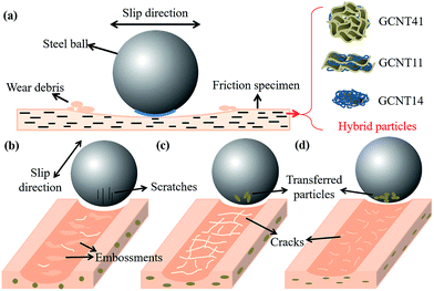
A classic study on the mechanisms of surface deformation of high performance polymers by Friedrich et al.54 revealed that there is not a simple correlation of the scratch resistance with other material properties, which is reasonable as well in the field of friction and wear, since tribological behavior of polymer composites can be subjected to numerous factors, such as dispersion and geometry of filler, interfacial adhesion, mechanical and thermo-mechanical properties, transfer film, processing technology and so on.55 In this work, we mainly focus on the differences in tribological mechanisms of GCNT41, GCNT11 and GCNT14 assemblies, which can be illustrated using Fig. 12 as model.
By adjusting the reaction ration of MG and MCNT, diverse combinational structures have been successfully established and the geometric shape as well as the combinational structure of the hybrids shows a great influence on tribological performance. In the case of GCNT41 (Fig. 12b), the lack of mechanical interlocking result in the poor interfacial compatibility with the matrix, and the ball-like shape impaired the protective effect of MG, which result in the relatively high friction coefficient. The graphene-covered structure of GCNT41 also shown up the scratching behavior during friction, as some slight scratches appeared on the coupled part. The embossments on the worn surface indicate that the wear type of GCNT41/PI is more like adhesive wear, similar to virgin PI, which means GCNT41 cannot exert the suppressive effect. By raising the content of MCNT, the GCNT assemblies tend to form the layered structure, like the multilayer sandwich structure of GCNT11 and the few-layer sheet structure of GCNT14. The latter offers an adequate platform to fulfill the protective and suppressive effect of MG and the isolation and transfer effect of MCNT (Fig. 12d), where the strong load-bearing capacity, the inhibition of large-size wear debris, the reduced particle size and the transferred particles on the coupled part combined together, realizing the optimal tribological performance in this system. Furthermore, the comparison of the tribological mechanisms of different GCNT assemblies is beneficial for us to have insight into the complicated relations between the structures of multidimensional nano-hybrids like GCNTs and the anticipatory enhancement effect. The performance of nanoparticle assemblies is more than a simple function of the intrinsic characteristics of precursor nanoparticles, and the combinational structure plays a significant role in achieving synergistic effect, as revealed in this work.
4. Conclusion
In this work, GCNT assemblies with diverse combinational structures were fabricated by adjusting the reaction ratio of MG and MCNT using covalent bonding method. To investigate the differences in enhancement performance related to structure, GCNT/PI composites were prepared by in situ polymerization and the mechanical, thermal-mechanical and tribological properties have been studied in detail. In the cases of GCNT11 and GCNT14, MG and MCNT show a synergistic effect with respect to elongation at break and wear rate and a complementary effect with respect to tensile strength and friction coefficient. Furthermore, the 0.5 wt% GCNT14 addition into PI resulted in a 29.3% reduction in friction coefficient and a 75.8% reduction in wear rate, ascribing to the suppressive and protective effect of graphene sheets as well as the isolation and transfer effect of MCNTs. However, properties of GCNT41/PI specimen, like tensile strength, storage modulus and lubricity, got degraded compared to MG/PI and MCNT/PI. This considerable change indicates that, as multidimensional nano-hybrids, the geometric structure of GCNT assemblies has a crucial influence on achieving optimal performance. In conclusion, this work gives an ingenious insight into the relationship between the microstructure and macro-properties, which has an important implication for the fabrication of nanoparticle assemblies.Conflict of interest
The authors declare no competing financial interest.Acknowledgements
This work was financially supported by the National Basic Research Program of China (Grant 2011CB605704).References
- T. Hanemann and D. V. Szabo, Materials, 2010, 3, 3468–3517 CrossRef CAS.
- S. C. Tjong, Mater. Sci. Eng., R, 2006, 53, 73–197 CrossRef.
- M. T. Mo, W. J. Zhao, Z. F. Chen, Q. X. Yu, Z. D. Zeng, X. J. Wu and Q. Xue, RSC Adv., 2015, 5, 56486–56497 RSC.
- H. Yan, S. Li, Y. Jia and X. Y. Ma, RSC Adv., 2015, 5, 12578–12582 RSC.
- Z. Y. Sui, Q. H. Meng, X. T. Zhang, R. Ma and B. Cao, J. Mater. Chem., 2012, 22, 8767–8771 RSC.
- Z. Bin, J. Mater. Sci.: Mater. Electron., 2016, 27, 10421–10426 CrossRef.
- J. Y. Kim, J. Lee, W. H. Lee, I. N. Kholmanov, J. W. Suk, T. Y. Kim, Y. F. Hao, H. Chou, D. Akinwande and R. S. Ruoff, ACS Nano, 2014, 8, 269–274 CrossRef CAS PubMed.
- A. Salam, L. A. Lucia and H. Jameel, ACS Appl. Mater. Interfaces, 2013, 5, 11029–11037 CAS.
- M. Yoonessi, J. A. Peck, J. L. Bail, R. B. Rogers, B. A. Lerch and M. A. Meador, ACS Appl. Mater. Interfaces, 2011, 3, 2686–2693 CAS.
- M. Naffakh, A. M. Diez-Pascual, C. Marco, G. J. Ellis and M. A. Gomez-Fatou, Prog. Polym. Sci., 2013, 38, 1163–1231 CrossRef CAS.
- M. M. J. Treacy, T. W. Ebbesen and J. M. Gibson, Nature, 1996, 381, 678–680 CrossRef CAS.
- X. Huang, Z. Y. Yin, S. X. Wu, X. Y. Qi, Q. Y. He, Q. C. Zhang, Q. Y. Yan, F. Boey and H. Zhang, Small, 2011, 7, 1876–1902 CrossRef CAS PubMed.
- Y. Chen, Y. M. Zhang and Y. Liu, Chem. Commun., 2010, 46, 5622–5633 RSC.
- S. Q. Liu and Z. Y. Tang, J. Mater. Chem., 2010, 20, 24–35 RSC.
- H. L. Ma, L. Zhang, Y. W. Zhang, S. J. Wang, C. Sun, H. Y. Yu, X. M. Zeng and M. L. Zhai, Radiat. Phys. Chem., 2016, 118, 21–26 CrossRef CAS.
- C. Tang, Q. Zhang, M. Q. Zhao, G. L. Tian and F. Wei, Nano Energy, 2014, 7, 161–169 CrossRef CAS.
- P. Feng, S. P. Peng, P. Wu, C. D. Gao, W. Huang, Y. W. Deng, T. Xiao and C. J. Shuai, Int. J. Nanomed., 2016, 11, 3487–3500 CrossRef PubMed.
- Z. Li, G. L. Fan, Q. Guo, Z. Q. Li, Y. S. Su and D. Zhang, Carbon, 2015, 95, 419–427 CrossRef CAS.
- Y. Hwang, M. Kim and J. Kim, J. Mater. Sci., 2013, 48, 7011–7021 CrossRef CAS.
- J. Y. Oh, Y. S. Kim, Y. Jung, S. J. Yang and C. R. Park, ACS Nano, 2016, 10, 2184–2192 CrossRef CAS PubMed.
- Y. Xiao, L. Liu, C. B. He, W. S. Chin, T. T. Lin, K. Y. Mya, J. C. Huang and X. H. Lu, J. Mater. Chem., 2006, 16, 829–836 RSC.
- S. J. Guo, D. Wen, Y. M. Zhai, S. J. Dong and E. K. Wang, ACS Nano, 2010, 4, 3959–3968 CrossRef CAS PubMed.
- D. Z. Zhang, Y. E. Sun, P. Li and Y. Zhang, ACS Appl. Mater. Interfaces, 2016, 8, 14142–14149 CAS.
- K. E. Prasad, B. Das, U. Maitra, U. Ramamurty and C. N. R. Rao, Proc. Natl. Acad. Sci. U. S. A., 2009, 106, 13186–13189 CrossRef CAS PubMed.
- S. Y. Yang, W. N. Lin, Y. L. Huang, H. W. Tien, J. Y. Wang, C. C. M. Ma, S. M. Li and Y. S. Wang, Carbon, 2011, 49, 793–803 CrossRef CAS.
- S. Chatterjee, F. Nafezarefi, N. H. Tai, L. Schlagenhauf, F. A. Nuesch and B. T. T. Chu, Carbon, 2012, 50, 5380–5386 CrossRef CAS.
- X. L. Yang, Y. Q. Zhan, J. Yang, J. C. Zhong, R. Zhao and X. B. Liu, J. Polym. Res., 2012, 19, 6 CrossRef.
- Y. S. Xin, T. S. Li, D. F. Gong, F. L. Xu and M. M. Wang, RSC Adv., 2017, 7, 6323–6335 RSC.
- T. Huang, T. S. Li, Y. S. Xin, B. C. Jin, Z. X. Chen, C. Su, H. M. Chen and S. Nutt, RSC Adv., 2014, 4, 19814–19823 RSC.
- T. X. Wang, L. Yuan, G. Z. Liang and A. J. Gu, Appl. Surf. Sci., 2015, 359, 754–765 CrossRef CAS.
- J. Y. Oh, G. H. Jun, S. Jin, H. J. Ryu and S. H. Hong, ACS Appl. Mater. Interfaces, 2016, 8, 3319–3325 CAS.
- J. H. Lin, Z. I. Lin, Y. J. Pan, C. K. Chen, C. L. Huang, C. H. Huang and C. W. Lou, Macromol. Mater. Eng., 2016, 301, 199–211 CrossRef CAS.
- T. Huang, Y. S. Xin, T. S. Li, S. Nutt, C. Su, H. M. Chen, P. Liu and Z. L. Lai, ACS Appl. Mater. Interfaces, 2013, 5, 4878–4891 CAS.
- I. Gofman, B. D. Zhang, W. C. Zang, Y. Zhang, G. L. Song, C. H. Chen and Y. Li, J. Polym. Res., 2013, 20, 258 CrossRef.
- X. J. Shen, X. Q. Pei, Y. Liu and S. Y. Fu, Composites, Part B, 2014, 57, 120–125 CrossRef CAS.
- C. E. Sroog, Prog. Polym. Sci., 1991, 16, 561–694 CrossRef CAS.
- M. S. Dresselhaus, A. Jorio, M. Hofmann, G. Dresselhaus and R. Saito, Nano Lett., 2010, 10, 751–758 CrossRef CAS PubMed.
- M. S. Dresselhaus, G. Dresselhaus and M. Hofmann, Philos. Trans. R. Soc., A, 2008, 366, 231–236 CrossRef CAS PubMed.
- Y. W. Cao, Z. L. Lai, J. C. Feng and P. Y. Wu, J. Mater. Chem., 2011, 21, 9271–9278 RSC.
- T. Huang, R. Lu, C. Su, H. Wang, Z. Guo, P. Liu, Z. Huang, H. Chen and T. Li, ACS Appl. Mater. Interfaces, 2012, 4, 2699–2708 CAS.
- W. Brostow, H. E. H. Lobland and M. Narkis, J. Mater. Res., 2006, 21, 2422–2428 CrossRef CAS.
- X. Z. K. Loy and S. K. Sinha, Wear, 2012, 296, 681–692 CrossRef CAS.
- D. Sun, W. N. Everett, C. C. Chu and H. J. Sue, Small, 2009, 5, 2692–2697 CrossRef CAS PubMed.
- K. L. White, M. Shuai, X. Zhang, H. J. Sue and R. Nishimura, Carbon, 2011, 49, 5124–5131 CrossRef CAS.
- X. Zhang, H. J. Sue and R. Nishimura, J. Mater. Chem., 2012, 22, 6156–6164 RSC.
- C. C. Chu, K. L. White, P. Liu, X. Zhang and H. J. Sue, Carbon, 2012, 50, 4711–4721 CrossRef CAS.
- P. Liu, K. L. White, H. Sugiyama, J. Xi, T. Higuchi, T. Hoshino, R. Ishige, H. Jinnai, A. Takahara and H. J. Sue, Macromolecules, 2013, 46, 463–473 CrossRef CAS.
- P. Liu, M. Mullins, T. Bremner, J. A. Browne and H. J. Sue, Polymer, 2016, 93, 88–98 CrossRef CAS.
- R. J. Young, I. A. Kinloch, L. Gong and K. S. Novoselov, Compos. Sci. Technol., 2012, 72, 1459–1476 CrossRef CAS.
- P. Samyn, G. Schoukens, F. Verpoort, J. Van Craenenbroeck and P. De Baets, Macromol. Mater. Eng., 2007, 292, 523–556 CrossRef CAS.
- K. Tanaka, Y. Uchiyama and S. Toyooka, Wear, 1973, 23, 153–172 CrossRef CAS.
- G. W. Yi and F. Y. Yan, Wear, 2007, 262, 121–129 CrossRef CAS.
- H. Wang, R. Lu, T. Huang, Y. Ma, P. Cong and T. Li, Mater. Sci. Eng., A, 2011, 528, 6878–6886 CrossRef CAS.
- K. Friedrich, H. J. Sue, P. Liu and A. A. Almajid, Tribol. Int., 2011, 44, 1032–1046 CrossRef CAS.
- I. M. Hutchings, in Tribology: Friction and Wear of Engineering Materials, Elsevier Limited, London, 1992 Search PubMed.
Footnote |
| † Electronic supplementary information (ESI) available: Schematic diagram of the contact configuration of the reciprocating friction and wear testing machines; Raman spectra of MG, MCNT and GCNT11; size distribution of GCNT41, GCNT11 and GCNT14; FESEM images showing half-open and intact graphene–CNT balls outside the fracture surface of GCNT41/PI specimen; storage modulus of PI composites at 150 °C and 200 °C; SEM images of worn surfaces and wear debris of virgin PI, MG/PI and MCNT/PI specimens. See DOI: 10.1039/c7ra02149f |
| This journal is © The Royal Society of Chemistry 2017 |

