 Open Access Article
Creative Commons Attribution 3.0 Unported Licence
High-flux, continuous oil spill collection by using a hydrophobic/oleophilic nanofibrous container†
Shanshan Qiu‡
a,
Lanlan Hou‡a,
Jingchong Liua,
Fengyun Guoa,
Yuanyuan Zhanga,
Lihua Zhangb,
Kai Liua,
Nü Wang *a and
Yong Zhao
 a
a
aKey Laboratory of Bioinspired Smart Interfacial Science and Technology of Ministry of Education, Beijing Key Laboratory of Bioinspired Energy Materials and Devices, School of Chemistry and Environment, Beihang University, Beijing 100191, China. E-mail: wangn@buaa.edu.cn; Fax: +86-10-82317801
bCollaborative Innovation Center for Nanomaterials & Optoelectronic Devices, College of Physics, Qingdao University, Qingdao 266071, China
First published on 3rd April 2017
Abstract
A hydrophobic/superoleophilic nanofibrous container was designed for the purpose of collecting oil spills. The device could continuously collect various kinds of oils from the surface of water and retain excellent stability when exposed to corrosive media. This work might provide a new strategy for designing fibrous membranes and applying them to the collection of oil spills.
With frequent oil spillage accidents occurring, removal of oil from such spills has become an urgent issue.1 The common methods for cleaning up after oil spills include mechanical extraction, oil skimming, in situ burning, chemical dispersion, and so on.2–4 However, these technologies have various limitations. Mechanical extraction requires a considerable consumption of energy and expenditure of time; oil skimmers are expensive and inefficient; and in situ burning results in secondary pollution. So it is urgent to develop a new technology for a continuous, in situ separation of oil from water and collection of the spilled oil.
Inspired by super-wetting surfaces in nature (e.g., the lotus leaf), plenty of materials with special wettability properties have been prepared and have achieved outstanding performances in oil/water separation.5,6 These materials are mainly classified into two categories: absorption materials (powders, sponges, aerogels, etc.) and filtration materials (membranes, meshes, fabrics, etc.). Of the various absorption materials, superhydrophobic and superoleophilic sponge materials7–10 have been particularly widely studied and considered as the preferential candidate for oil spill cleanups because of their direct absorption of oils from the surface of water. Unfortunately, the absorbed oils need to be mechanically extruded from these materials for these materials to be re-used, and such a process is cumbersome when contending with an oil spill. Recently, researchers11 realized a continuous separation of oil from water by connecting the porous hydrophobic/oleophilic materials (e.g., carbon-based sponges and functional polymer sponges) to a pump. However, operations based on these designs might damage the internal structure of the materials, and hence diminish their stability for long-term use.
The other strategy for cleaning up after oil spills involves taking advantage of filtration materials in the forms of mesh-based materials,10,12–14 ceramic microfiltration membranes,15,16 filter paper,17,18 fabric,19,20 and polymer membranes.21–23 Since Jiang and co-workers24 first reported a superhydrophobic/superoleophilic Teflon-coated metal mesh for separating oil from water, numerous filtration materials with special wettability properties have been proposed for oil/water mixture separation. However, the water forms a barrier layer on the membranes that, for the light oil/water mixtures, prevents the oil from passing through during the separation process. So the surface oil must be collected first and then separated,17,25,26 which is energy intensive and impractical in in situ oil spill cleanups. Recently, some investigations have been reported in which the materials were utilized after they had been modified for in situ oil spills cleanups. For example, an automatically operating oil/water separation apparatus was designed by folding a modified copper mesh into a mini “oil boat”, which could float freely on the water surface and separate oil from the water surface in situ.27 Shao et al. designed a boat made of fabric for automatic oil spill cleanups by modifying the polydopamine on the fabric surface.28 Nevertheless, the large-scale fabrication and practical application of these materials are limited since most of the fabrication processes require complex and high-cost treatments such as hydrothermal disposal, phase deposition, electrochemical methods, colloidal deposition and so forth.19,29–31 Thus, an ideal device designed for oil spill cleanups need to satisfy the following three conditions: (1) be made of materials that are inexpensive and easy to fabricate on a large scale; (2) show continuous and efficient separation abilities for a wide variety of oils; and (3) be stable when exposed to complex environmental conditions so that it can be used for long-term applications.
Herein, a facile poly(vinylidene fluoride–hexafluoropropylene) (PVDF–HFP) nanofibrous container was designed via a simple electrospinning method that is easy to scale up. The nanofibrous container could realize in situ, self-driven and continuous collection of oil spills. Moreover, the fibrous container showed the advantages of high flux, an ability to nearly exclusively collect oil from an oil–water mixture with the oil contents of the collected oil being more than 99%, and excellent stability toward strong acid, alkali and salt media in the environment. Thus, we expect the fibrous membrane design developed in this work to find practical applications in dealing with oil spills.
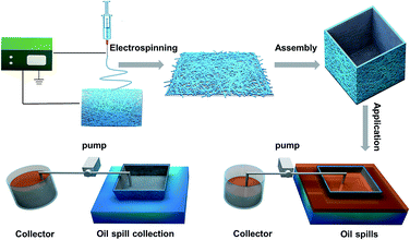
Scheme 1 shows a schematic diagram of the process used to fabricate our fibrous oil spill container and its application in the collection of oil spills. First, the PVDF–HFP nanofibrous membrane was electrospun onto a stainless steel mesh and folded to form a fibrous container. Then the container was put into mixtures of water and oil in which the oil could penetrate into the container. By connecting the container to a pump, the separated oil could be continuously removed from the fibrous container and collected. The whole separation process could continue without interruption until the surface of the water was clean.
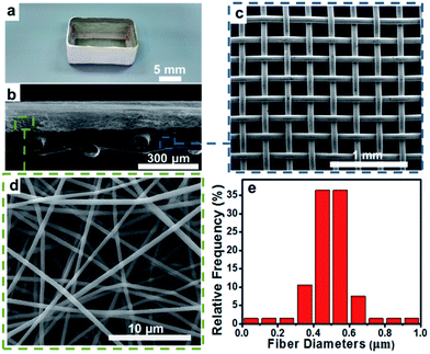
The structure of the electrospun fibrous container is shown in Fig. 1. Fig. 1a shows an optical photograph of the fibrous container, the outer layer of which is a PVDF–HFP nanofibrous membrane. The cross-sectional scanning electron microscopy (SEM) image of the dual-layer film is shown in Fig. 1b; a uniform layer of PVDF–HFP nanofibers was electrospun onto the stainless steel mesh to yield the dual-layer structure. The tensile strength of the dual-layer film was nearly the same as that of the single-layer stainless stain mesh, which overcame the difficulty of applying the single PVDF–HFP membrane in the environment (Fig. S1†). SEM images of the stainless steel mesh and PVDF–HFP membrane were also acquired and are shown in Fig. 1c and d. The stainless steel mesh was observed to have a square pore structure with a pore size of about 225 μm; such a pore size would not hinder the flux through the fibrous membrane (Fig. S2†). The PVDF–HFP membrane exhibited non-woven surfaces with numerous interconnected micropores, and consisted of many relatively uniform nanofibers with an average diameter of 500 nm (Fig. 1e).
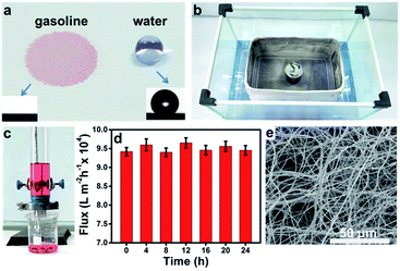
The wetting behavior of the fibrous container was studied by taking contact angle (CA) measurements. The untreated stainless steel mesh was found to be amphiphilic, while the PVDF–HFP membrane showed different levels of wettability towards water and oil. As shown in Fig. 2a, a gasoline droplet (dyed red with Sudan II) wet the membrane within 0.8 s, while the water droplet (dyed lilac with Crystal Violet) showed a spherical shape on the membrane and exhibited a water contact angle (WCA) of 134.0 ± 3.2° (other OCAs are shown in Fig. S3†). Furthermore, the fibrous container freely floated on the water surface even when loaded with five times its own weight (200 g), and no water penetrated into the container through the pores (Fig. 2b). The above results demonstrated the good hydrophobicity/superoleophilicity of the PVDF–HFP membrane. It has been shown that the pores of the nanofibrous membrane can easily become blocked by impurities in the oil, resulting in a decrease in flux32 and hence hindering the practical application of the membrane. In order to test the effectiveness of the PVDF–HFP membrane, experiments measuring flux through of the membrane were carried out using a home-made setup (Fig. 2c). The results showed that the flux through the PVDF–HFP membrane to be inversely proportional to the thickness of the membrane and the viscosity of the liquid (Fig. S4 and S5†), consistent with the predictions of the Hagen–Poiseuille equation.33,34 By comparing the durability and separation flux of a series of membranes, an electrospinning time of 60 min was selected as optimal. Moreover, the flux of gasoline remained greater than 9.4 × 10⁴ L m−2 h−1 over the course of 24 h (Fig. 2d), demonstrating the high flux stability of the PVDF–HFP membrane. The PVDF–HFP membrane maintained its non-woven mats and three-dimensional porous structures even after being immersed in gasoline for 24 h (Fig. 2e).
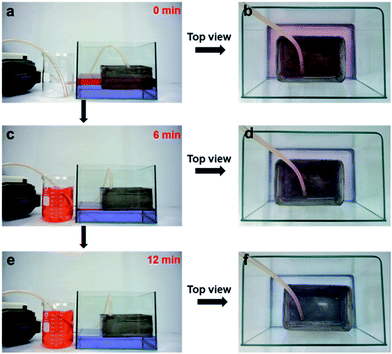
In order to test the feasibility of using the fibrous container, a continuous in situ oil–water separation system was designed. As Fig. 3 shows, gasoline dyed red was used to simulate an oil spill, while the water was dyed lilac. As the fibrous container contacted the gasoline surface of the mixture, the gasoline quickly penetrated into the container through the pores due to its superoleophilicity. When the pump was turned on, oil was continuously extracted from the fibrous container, and finally collected in the beaker until the gasoline on the water surface was almost completely collected (see the movie in the ESI† and see Fig. 3a, c and e). Additionally, Fig. 3b, d, and f show optical images of the top of the oil/water mixture during the separation process. When the entire process was finished, clean water was left without gasoline stains visible, and no water droplet was observed in the collected gasoline as well. Thus the device could realize a continuous in situ collection of oil from the surface of water. It is worth noting that the whole separation process required no manual operation, and this automatic feature is beneficial when dealing with oil spills in complex environments.
The continuous separation was modeled to be largely driven by the action of the pressure difference (ΔP) caused by the difference between the levels of the liquids (ΔH). As Fig. 4a and b illustrate, the oil could permeate into the fibrous container under a ΔP until the height of the oil in the fibrous container reached the same level of the oil layer on the outside water surface. After extracting the oil from the “fibrous container”, the level of the oil layer decreased, resulting in a decrease in the ΔP, according to the proposed mechanism, and a corresponding reduction of the collection rate (Fig. 4c–e). Note that a certain level of ΔH remained throughout the whole collection process, caused by the depth of the container in the water which is caused by the gravity of the container. As the process continued, the suction force according to the proposed mechanism became the major driver of the residual continuous separation process until the oil layer vanished, which would further improve the separation efficiency of this design compared to other separation designs.27,28
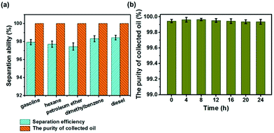
In order to verify the oil–water selectivity of the fibrous container, separation efficiencies for various kinds of oils and organic solvents were measured. As shown in Fig. 5a, the separation efficiencies of gasoline, hexane, petroleum ether, dimethylbenzene, and diesel were measured to be 97.93%, 97.71%, 97.49%, 98.32%, and 98.43%, respectively. During the separation process, the oils inevitably evaporated, which reduced the separation efficiency. The separation efficiency tests were thus also conducted in a sealed environment. The separation efficiencies in the sealed environment were found to be 0.29–1.01% better than those in the exposed environment, depending on the volatility of the sample tested (Fig. S6†). Moreover, the purity levels of the oils collected in the sealed environment were all greater than 99.99% (Fig. 5a). The results taken together showed that the as-prepared fibrous container could efficiently collect various kinds of oils and organic solvents from the water surface, and is hence suitable for dealing with various types of oil spill accidents. Besides the high oil–water selectivity, the durability of the as-prepared fibrous container was also investigated. The purity of a collected oil (gasoline) sample remained greater than 99.99% over the course of 24 h (Fig. 5b), demonstrating the excellent durability of the fibrous container.
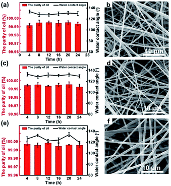
Another important feature of our fibrous container is its resistance to becoming corroded in actual marine environments and some special high-corrosion settings. A series of tests aimed at separating gasoline from corrosive solutions were conducted and corresponding WCAs were measured. Fig. 6a, c, and e show the effects of the separation time on the purity of the collected gasoline and on the WCA of the membranes in conditions containing various corrosive media, specifically 1 M HCl, 1 M NaOH, and 1 M NaCl. For each case, the purity of the collected oil was greater than 99.99%, and the WCA of the PVDF–HFP membrane was larger than 130.0° after immersing in the corrosive solution for 24 h. More importantly, the morphologies of the membranes immersed in these corrosive solutions for 24 h were observed to be similar to those of the membranes before being immersed, having retained the non-woven morphology (Fig. 6b, d and f). All of these results indicated the fibrous container to have excellent structural stability even when exposed to corrosive media.
Conclusion
We employed the electrospinning method to produce a PVDF–HFP fibrous container that was found to be easy to use for the collection of oil after oil spills. The results of our experiments demonstrated that the fibrous container could continuously collect various kinds of oils rapidly without any extra manual intervention. Furthermore, the container showed high separation selectivity, with the purity of the collected oil above 99% after the container was operating continuously for 24 h. More importantly, the separation ability of the container was shown to be highly stable even when the container was exposed to various corrosive media. Therefore, the fibrous container designed in this work might find practical applications in cleanup after oil spills and in wastewater treatment.Acknowledgements
The authors acknowledge the NSFC (21433012, 21374001, 21134003, 21222309), the National Instrumentation Program (2013YQ120355), the Program for New Century Excellent Talents in University of China, the Fundamental Research Funds for the Central Universities and the China Scholarship Council (201506025110).References
- M. A. Shannon, P. W. Bohn, M. Elimelech, J. G. Georgiadis, B. J. Marinas and A. M. Mayes, Nature, 2008, 452, 301–310 CrossRef CAS PubMed.
- J. Aurell and B. K. Gullett, Environ. Sci. Technol., 2010, 44, 9431–9437 CrossRef CAS PubMed.
- R. Boopathy, S. Shields and S. Nunna, Appl. Biochem. Biotechnol., 2012, 167, 1560–1568 CrossRef CAS PubMed.
- M. Roulia, K. Chassapis, C. Fotinopoulos, T. Savvidis and D. Katakis, Spill Sci. Technol. Bull., 2003, 8, 425–431 CrossRef CAS.
- B. Wang, W. Liang, Z. Guo and W. Liu, Chem. Soc. Rev., 2015, 44, 336–361 RSC.
- H. Bellanger, T. Darmanin, E. Taffin de Givenchy and F. Guittard, Chem. Rev., 2014, 114, 2694–2716 CrossRef CAS PubMed.
- N. Chen and Q. Pan, ACS Nano, 2013, 7, 6875–6883 CrossRef CAS PubMed.
- D. D. Nguyen, N.-H. Tai, S.-B. Lee and W.-S. Kuo, Energy Environ. Sci., 2012, 5, 7908–7912 CAS.
- J. Li, C. Xu, Y. Zhang, R. Wang, F. Zha and H. She, J. Mater. Chem. A, 2016, 4, 15546–15553 CAS.
- J. Li, L. Yan, H. Li, J. Li, F. Zha and Z. Lei, RSC Adv., 2015, 5, 53802–53808 RSC.
- J. Ge, Y.-D. Ye, H.-B. Yao, X. Zhu, X. Wang, L. Wu, J.-L. Wang, H. Ding, N. Yong, L.-H. He and S.-H. Yu, Angew. Chem., Int. Ed., 2014, 53, 3612–3616 CrossRef CAS PubMed.
- Z. Xue, S. Wang, L. Lin, L. Chen, M. Liu, L. Feng and L. Jiang, Adv. Mater., 2011, 23, 4270–4273 CrossRef CAS PubMed.
- C. R. Crick, J. A. Gibbins and I. P. Parkin, J. Mater. Chem. A, 2013, 1, 5943–5948 CAS.
- S. Zhang, F. Lu, L. Tao, N. Liu, C. Gao, L. Feng and Y. Wei, ACS Appl. Mater. Interfaces, 2013, 5, 11971–11976 CAS.
- J. Cui, X. Zhang, H. Liu, S. Liu and K. L. Yeung, J. Membr. Sci., 2008, 325, 420–426 CrossRef CAS.
- S. H. Hyun and G. T. Kim, Sep. Sci. Technol., 1997, 32, 2927–2943 CrossRef CAS.
- S. Wang, M. Li and Q. Lu, ACS Appl. Mater. Interfaces, 2010, 2, 677–683 CAS.
- M. Zhang, C. Wang, S. Wang, Y. Shi and J. Li, Appl. Surf. Sci., 2012, 261, 764–769 CrossRef CAS.
- B. Cortese, D. Caschera, F. Federici, G. M. Ingo and G. Gigli, J. Mater. Chem. A, 2014, 2, 6781–6789 CAS.
- X. Zhou, Z. Zhang, X. Xu, F. Guo, X. Zhu, X. Men and B. Ge, ACS Appl. Mater. Interfaces, 2013, 5, 7208–7214 CAS.
- W. Ma, Q. Zhang, D. Hua, R. Xiong, J. Zhao, W. Rao, S. Huang, X. Zhan, F. Chen and C. Huang, RSC Adv., 2016, 6, 12868–12884 RSC.
- J. Zhang and S. Seeger, Adv. Funct. Mater., 2011, 21, 4699–4704 CrossRef CAS.
- X. Tang, Y. Si, J. Ge, B. Ding, L. Liu, G. Zheng, W. Luo and J. Yu, Nanoscale, 2013, 5, 11657–11664 RSC.
- L. Feng, Z. Zhang, Z. Mai, Y. Ma, B. Liu, L. Jiang and D. Zhu, Angew. Chem., Int. Ed., 2004, 43, 2012–2014 CrossRef CAS PubMed.
- D. Tian, X. Zhang, X. Wang, J. Zhai and L. Jiang, Phys. Chem. Chem. Phys., 2011, 13, 14606–14610 RSC.
- B. Wang, Y. Zhang, W. Liang, G. Wang, Z. Guo and W. Liu, J. Mater. Chem. A, 2014, 2, 7845–7852 CAS.
- F. Wang, S. Yu, M. Xue, J. Ou and W. Li, New J. Chem., 2014, 38, 4388–4393 RSC.
- Z. Wang, Y. Xu, Y. Liu and L. Shao, J. Mater. Chem. A, 2015, 3, 12171–12178 CAS.
- J. Li, L. Shi, Y. Chen, Y. Zhang, Z. Guo, B.-l. Su and W. Liu, J. Mater. Chem., 2012, 22, 9774–9781 RSC.
- C. Su, Y. Xu, W. Zhang, Y. Liu and J. Li, Appl. Surf. Sci., 2012, 258, 2319–2323 CrossRef CAS.
- C. Tan, Q. Li, Y. Li, C. Zhang and L. Xu, RSC Adv., 2016, 6, 53813–53820 RSC.
- J. Wei, G. S. Helm, N. Corner-Walker and X. Hou, Desalination, 2006, 192, 252–261 CrossRef CAS.
- K. Scott, Handbook of industrial membranes, Elsevier, 1995 Search PubMed.
- J. R. V. Wazer, J. W. Lyons, K. Y. Kim, R. E. Colwell and H. Leaderman, Phys. Today, 1964, 17, 66–70 CrossRef.
Footnotes |
| † Electronic supplementary information (ESI) available. See DOI: 10.1039/c7ra01990d |
| ‡ These authors contributed equally to this work. |
| This journal is © The Royal Society of Chemistry 2017 |

