 Open Access Article
Creative Commons Attribution 3.0 Unported Licence
A new insight into the rechargeable mechanism of manganese dioxide based symmetric supercapacitors
Hongyuan Chen a,
Sha Zengab,
Minghai Chen*a,
Yongyi Zhanga and
Qingwen Lia
aDivision of Advanced Nanomaterials, Key Lab of Nanodevices and Applications, Suzhou Institute of Nano-Tech and Nano-Bionics, Chinese Academy of Sciences, Suzhou 215123, P. R. China. E-mail: mhchen2008@sinano.ac.cn; Fax: +86 512 62872806; Tel: +86 512 62872806
bUniversity of Chinese Academy of Sciences, Beijing, 100049, P. R. China
First published on 26th January 2017
Abstract
Pseudocapacitive symmetric supercapacitors, where both the cathode and the anode have the same pseudocapacitive material, have been widely investigated for developing high-performance supercapacitors. However, being different from electrochemical double-layer (EDL) capacitive electrodes, the charge storage of pseudocapacitive materials relies on reversible redox reactions that change the ion valence status, which is not the case for EDL capacitors (EDLCs). In this research, as a typical inorganic pseudocapacitive material for supercapacitors, a manganese dioxide (MnO2) based symmetric supercapacitor was carefully investigated by using a flexible and ultra-light carbon nanotube (CNT) film as the current collector and substrate for MnO2 electrodeposition. The results indicated that the pristine active material on the positive electrode showed no change after cyclic charging/discharging, but only served as a stable counter electrode and reference electrode. The main redox reaction for the energy storage of the supercapacitor occurred on the negative electrode. Furthermore, the dissolved Mn2+ ions on the negative electrode were deposited onto the positive electrode, which induced an increase in mass of the positive electrode and a decrease in mass of the negative electrode. This research could give new insight into the working mechanism of MnO2 electrodes and other pseudocapacitive materials in symmetric supercapacitors.
Introduction
Nowadays, air pollution and global warming trends largely accelerate the development of effective conversion and storage technologies for clean energy.1 It remains a key aim to develop energy storage devices with high capacities and high energy densities which also meet other requirements such as having environmentally friendly properties, low costs and long lifetimes.2,3 Supercapacitors have attracted much attention for their superior power densities and lifetimes in comparison with other batteries.4–6 However, the specific capacitance of a commercialized supercapacitor based on electrochemical double-layer (EDL) charge storage was much lower than peoples’ expectations.6 In order to further increase the specific capacitance of supercapacitors, pseudocapacitive materials with reversible electrochemical redox reactions were tested as the electrodes of supercapacitors.7 These pseudocapacitive materials mainly include inorganic metallic compounds (oxides, hydroxides, sulfides and others)8–10 and conductive polymers.11 Symmetric pseudocapacitive supercapacitors with the same pseudocapacitive material in both the positive and negative electrodes have simple structures and could be easily assembled with higher specific capacitances than EDL capacitors (EDLCs), thus they have been widely used to exhibit the electrochemical capacitive performance of pseudocapacitive materials,12–29 and they have a large potential as high-capacitance supercapacitors. Various pseudocapacitive materials such as polyaniline,12–15 manganese dioxide (MnO2),16–22 Ni/Co based oxides and hydroxides (including NiO,23 Co3O4,24 NiCo2O4,25,26 NiMnO4,27 NiFe2O4,28 CoMn hydroxide,29 etc.) have already been tested for use in symmetric supercapacitors.However, pseudocapacitive materials have different charge storage mechanisms than porous EDL materials, thus the working process of full cell symmetric supercapacitors based on pseudocapacitive electrodes has not been explained as simply as the process for EDLCs. The charge storage of pseudocapacitive materials relies on the reversible redox reaction of the electrode materials, such as the valence change of the metallic ions in metallic compounds.8 Therefore, the voltage increase of the symmetric supercapacitor in the charging process is dependent on the oxidation and reduction of the electrodes. However, for many metallic compounds such as metallic oxides, the metallic ion valences are at their highest or lowest values, and cannot be further oxidized or reduced. Typically, MnO2, which has been widely used in the electrodes of pseudocapacitive symmetric supercapacitors, has the highest valence among manganese oxides, thus it cannot be further oxidized as the positive electrode, but can be reduced to Mn3+ compounds in negative electrodes.30–32 Similarly, nickel compounds with Ni2+ ions (such as NiO and Ni(OH)2) could be oxidized to Ni3+ and Ni4+, but cannot be further reduced.33 As a result, it still remains an unanswered problem as to what role these metallic compounds serve in an electrode when they cannot be further oxidized or reduced.
In this research, the working process of a MnO2 based symmetric supercapacitor was investigated by using a flexible carbon nanotube (CNT) film as the conductive substrate for MnO2 electrodeposition. The results indicated that there was no obvious Mn compound precipitation in the electrolyte of the symmetric supercapacitor, which is largely different from MnO2 based electrodes in a three-electrode system. Structure analysis revealed that there were no obvious redox reactions for pristine MnO2 on the positive electrodes. In another word, pristine oxidation MnO2 on the positive electrode served only as a reference electrode that maintains a high oxidation status, while MnO2 on the negative electrode was reduced to Mn3+ compounds during the charging process which increased the voltage of the device from 0 V to 1 V. Furthermore, soluble Mn2+ generated from the disproportionation reaction and the excessive reduction of Mn3+ could migrate from the negative electrode to the positive electrode and be oxidized to Mn3+ compounds and MnO2 on the positive electrode, which could induce performance fading of the device. These results reveal the low utilizing efficiency of the materials and the fading mechanism of MnO2 based symmetric supercapacitors, and are valuable for the design of pseudocapacitive symmetric supercapacitors.
Experimental
A flexible CNT film, prepared via a floating catalyst chemical vapour deposition (FCCVD) method (supplied by Suzhou Creative Nano Carbon Co., Ltd.), was chosen as the conductive substrate for the electrodeposition of MnO2 onto it for the construction of a composite electrode. MnO2 was deposited onto the CNT film by a typical galvanostatic electrodeposition method in a two-electrode system, in which a graphite sheet that had the same area as the CNT film in the electrolyte was both the counter electrode and the reference electrode,34 and the current density was 5.0 mA cm−2 with 20 min deposition. This CNT film substrate was chemically stable and light, thus it was an ideal material for the observation of MnO2 on it with a high loading mass.The morphologies and microstructures of the samples were systematically investigated by field emission scanning electron microscopy (FE-SEM, Quanta 400 FEG, FEI) and X-ray diffraction (XRD, D8 Advance Powder X-ray diffractometer, Bruker AXS). Electrochemical experiments were carried out on a CHI-660C electrochemical workstation and using LANHE CT2001A electrochemical cell test equipment. A three-electrode system was used to test the electrochemical performance of the electrode without any other current collectors, polymer binders or conductive fillers. A platinum wire was used as the counter electrode, and a calomel electrode was used as the reference electrode. 1 M Na2SO4 aqueous solution was chosen as the electrolyte. The symmetric supercapacitor test was carried out in a beaker with 1 M Na2SO4 aqueous solution, and two pieces of CNT film with MnO2 were immersed into the beaker to serve as the positive and negative electrodes. These open test conditions with abundant electrolyte were beneficial for the observation of the symmetric supercapacitor working process. This experimental design is shown in Fig. 1(a).
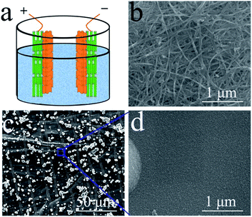 | ||
| Fig. 1 The scheme of the pseudocapacitive symmetric supercapacitor test design (a); SEM morphology of pristine CNT film (b) and the MnO2 nanosheets coated on a CNT film substrate (c, d). | ||
Results and discussion
The morphology of the pristine CNT film is shown in Fig. 1(b). The image reveals that the CNT film was formed by a dense CNT network with CNT bundles, which should be attributed to its special growth mechanism. These bundles contain thin CNTs with few wall numbers. The dense network with thin CNTs induced the high conductivity and excellent mechanical performance of the film. However, the hydrophobic surface of the film prevented the electrolyte from penetrating into the film, thus most of the MnO2 was deposited on the surface of the film, which only served as a light and conductive film substrate without pores. The resultant MnO2 nanostructure is shown in Fig. 1(c) and (d). The thin MnO2 nanosheets assembled into a thick layer on the CNT film. These thin nanosheets with high surface areas can largely increase the utilization of MnO2 as a pseudocapacitive material.35 The loading mass of MnO2 on the composite film was about 90 wt% (27 mg per electrode). With the aim of increasing the practical capacitance of the electrodes, carbonous materials are better than metallic substrates as the current collector for MnO2 based electrodes in supercapacitors.36 This composite film can be effectively used to investigate the electrochemical performance of the single electrode and the symmetric supercapacitor.Fig. 2(a) shows a typical cyclic voltammetry (CV) curve of the symmetric supercapacitor at a scan rate of 2 mV s−1. This curve reveals an excellent shape for supercapacitors, and is similar to the shape observed for EDLCs based on porous carbonous electrodes, which should be attributed to the continuous oxidation/reduction of Mn4+/Mn3+ in the oxide electrodes. As a typical pseudocapacitive metallic oxide, MnO2 stores electrochemical energy in the following redox reactions:
| (MnO2)surface + C+ + e− ↔ (MnOOC)surface | (1) |
| MnO2 + C+ + e− ↔ MnOOC | (2) |
C+ is the electrolyte cation (H+, Li+, Na+ and K+), and it is the cations but not the protons in the electrolyte that largely affect the practical capacitance of MnO2.37 Eqn (1) and (2) are the two different mechanisms of the MnO2 pseudocapacitive reactions that have been put forward to explain the energy storage mechanism of MnO2, and represent the surface faradaic reaction and the bulk faradaic reaction, respectively. The surface faradaic reaction mainly occurs on the surface of MnO2, while the bulk faradaic reaction relies on the intercalation or deintercalation of electrolyte cations in the bulk of the MnO2.30 However, both of the mechanisms rely on the reduction of Mn4+ to Mn3+. Experimental results revealed that the pseudocapacitive reaction happened in a very thin layer of MnO2,38 thus thin MnO2 nanosheets grown on CNT film can exhibit higher practical capacitance than thick particles.
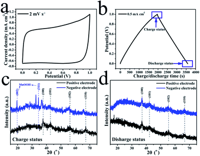
As is mentioned above, the oxidizing valences of the Mn ion in the positive and negative electrodes are both near 4+, which is the highest valence in MnOx oxides; only a tiny valence difference resulted in a small voltage between the two electrodes (usually lower than 10 mV), which can be used to divide the two electrodes into the positive electrode and negative electrode. However, to charge the device with an enlarged voltage, there must be reversible reactions on the electrodes, which should induce a change in the crystal structures. An experiment was designed to investigate this change. Four pieces of composite electrodes with the same structure and MnO2 content were produced. The symmetric supercapacitor with two composite electrodes was charged to 1 V and subsequently the two electrodes were lifted out of the solution to be washed clean and then tested by XRD analysis. The other electrodes were charged to 1 V and discharged to 0 V, and then washed for XRD testing. The charging/discharging current density of the two tests was 0.5 mA cm−2 and the stop positions of the two tests are shown in Fig. 2(b), which also shows a typical charging/discharging curve of a supercapacitor, with a perfect triangle shape and an ultra-low IR drop. The XRD patterns of the positive and negative electrodes in their charging (1 V) and discharging (0 V) statuses are shown in Fig. 2(c) and (d), respectively. The results reveal that the crystal structure of MnO2 on the positive electrode is similar to γ-MnO2 with four typical diffraction peaks (2θ: 37° for (100), 42° for (101), 56° for (102) and 67° for (110), ICDD/JCPDS PDF no. 30-0820). However, the pattern of the negative electrode in its charging status is largely different from that of the positive electrode as shown in Fig. 2(c), which indicated that a phase change happened only on the negative electrode and not on the positive electrode. All of the four main diffraction peaks of the MnO2 negative electrodes moved to the left, which should be attributed to the enlargement of interplanar spacing induced by the intercalation of H+/Na+ in the electrolyte. Furthermore, new diffraction peaks were displayed for the negative electrode, which may correspond to MnOOH (2θ: 19° for (002) and 34° for (311), ICDD/JCPDS PDF no. 18-0804) and the remnant Na2SO2 from the electrolyte. This means that the voltage enlargement of the symmetric supercapacitor was achieved by the reduction of MnO2 on the negative electrode, but no redox reactions occurred on the positive electrode. In the discharging status as shown in Fig. 2(d), the two electrodes have similar XRD patterns to γ-MnO2, which indicates that Mn compounds on the negative electrode were oxidized back to MnO2. From these XRD pattern comparisons, it is clear that only MnO2 on the negative electrode had an obvious redox reaction in the electrochemical charging/discharging process of the symmetric supercapacitors, and MnO2 on the positive electrode served as a reference electrode with high valence Mn ions (4+). Certainly, the electrodeposited MnO2 usually had a little lower valence than 4+, thus the charging process can further oxidize the Mn ions of MnO2 on the positive electrodes to the highest Mn ion valence in MnOx (4+). This reveals that only the capacity of one MnO2 electrode was utilized, which limited the practical capacitance of the full device.
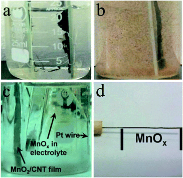
The optical observation of the MnO2 based symmetric supercapacitor and the MnO2 electrode in a three-electrode system also reveals an obvious difference, as shown in Fig. 3. The electrolyte of the symmetric supercapacitor remained clean even after more than 500 cycles of charging/discharging at a current density of 0.5 mA cm−2 (see Fig. 3(a)). However, the same MnO2/CNT composite in a three-electrode system (−0.1 to 0.8 V vs. SCE) exhibited serious Mn compound precipitation after fewer than 50 cycles of charging/discharging, as shown in Fig. 3(b). The precipitates should be the compounds of Mn3+ (MnOOH or MnOONa). In the three-electrode system, the dissolution of MnO2 into the electrolyte is a common phenomenon, which largely induces the poor cyclic performance of the electrode, and can be optimized by the heat treatment of MnO2 and using fresh electrolyte.36 To further investigate whether the precipitate was separated from the MnO2 electrode, observations were focused on the three-electrode system. The results are shown in Fig. 3(c) and (d). Fig. 3(c) reveals that the yellow/brown precipitate was generated beside the Pt wire counter electrode but not the MnO2 electrode. Besides being a possible dissolution–re-deposition mechanism for MnO2 pseudocapacitive energy storage,39,40 it is also an important side reaction for the disproportionation reaction of Mn3+ in MnO2 when used as the electrode of supercapacitors.41 In this reaction, Mn3+ can convert to Mn4+ and Mn2+ as shown in the following equation, and the latter ion is soluble in the electrolyte:
| Mn3+ ⇒ Mn2+ + Mn4+ |
The excess reduction of Mn4+ may also generate Mn2+. The dissolved Mn2+ ions were mainly generated in the discharging process of this electrode, and could easily migrate towards the Pt wire in the electrical field which served as the positive electrode in the discharging process. The positive charge on the Pt wire can oxidize these Mn2+ ions to Mn3+ compounds and MnO2. However, the low specific area of the Pt wire cannot provide enough surface area for continuous Mn compound deposition, thus some of the precipitate was separated from the Pt wire and moved into the electrolyte. Finally, the precipitate aggregated and was deposited into the bottom of a beaker as shown in Fig. 3(b). Fig. 3(d) shows the optical morphology of the Pt wire after the electrochemical charging/discharging cyclic tests. It exhibits a black color in the part of the Pt wire that was immersed in the electrolyte, which should be deposited MnO2. This observation reveals that there exists mass migration from MnO2 to the Pt wire. In the MnO2 based symmetric supercapacitor, this mass migration may also exist in the charging/discharging process, and should be investigated in designed experiments.
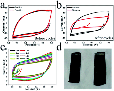
A symmetric supercapacitor was also constructed as shown in Fig. 1(a). As stated above, the initial loading mass of MnO2 on both of the two electrodes was 27 mg per electrode. The electrochemical capacitive performances of the positive and negative electrodes were tested in three-electrode systems by a CV method before and after 50 cycles of charging/discharging at 0.5 mA cm−2 for the full device, respectively. The results are shown in Fig. 4. Nearly the same CV curves are seen for the two electrodes at a scan rate of 5 mV s−1 before the cyclic test, as shown in Fig. 4(a). The specific capacitances can be calculated from the CV curves. According to Fig. 4(a), the initial specific capacitance of the single electrode at a 5 mV s−1 scan rate was 89 F g−1. However, after 50 cycles of charging/discharging, the cycle area of the CV curve for the negative electrode was much smaller than the cycle area for the positive electrode, while the latter exhibits an area similar to that of the electrode before the cyclic test (see Fig. 4(b)). This indicates the large capacitance fading of the negative electrode after the test, which may be attributed to the loss of mass of the negative electrode. In contrast, nearly no capacitance loss occurred on the positive electrode. The CV curves of the full supercapacitor for the first eight cycles are shown in Fig. 4(c). The initial specific capacitance of the symmetric supercapacitor was 22 F g−1. These results reveal the fast capacitance fading in this process, which should be attributed to the capacitance fading of the negative electrode. However, there is no obvious precipitation in the electrolyte after the cyclic test as shown in Fig. 3(a), which means that at least most of the lost mass of the negative electrode was not dissolved into the electrolyte. The optical morphologies of the two electrodes after 50 cycles are shown in Fig. 4(d), in which the positive electrode seems much more black than the negative electrode. Weighing the electrodes revealed that the mass of the positive electrode was 30 mg but that of the negative electrode was 24 mg, although the area of the positive electrode was even a little lower than that of the negative electrode. There surely existed a large mass difference between the two electrodes after the electrochemical cycles. Considering the capacitance fading of the negative electrode, this indicated that the mass on the negative electrode may have migrated onto the positive electrode in the electrochemical cyclic process.
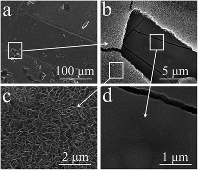
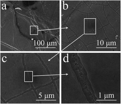
Fig. 5 and 6 show the surface morphologies of the two electrodes after the cyclic test. Fig. 5 shows the morphologies of the positive electrode. Compared with its initial morphology as shown in Fig. 1(b), a new layer of MnO2 was deposited on the positive electrode. The scale of the MnO2 nanosheets is much larger than on the pristine electrode, similar to the morphologies of the dissolution–re-deposition converted MnO2 nanosheets in a three-electrode system.38,41 From the broken area of this layer, the pristine MnO2 layer formed by thin nanosheets can be seen in Fig. 5(b). The morphology comparison of the new layer and the pristine layer is shown in Fig. 5(c) and (d), which reveals a large difference. The porous surface with large pores for the new MnO2 layer made it black as shown in Fig. 4(d). It can be assumed that this new layer was electrodeposited onto the positive electrode, but not from the conversion of the pristine MnO2 layer, because the latter layer was intact, as seen in the SEM images in Fig. 5(b) and (d). Furthermore, there were no Mn ions in the pristine Na2SO4 aqueous electrolyte. Thus this new layer may be from the negative electrode. The SEM images of the negative electrode as shown in Fig. 6 confirmed this suspicion. Wrinkles are exhibited on the negative electrode as shown in Fig. 6(a), and the depth of the cracks on the MnO2 layer largely decreased. The CNT layer under MnO2 can even be seen from the cracks as shown in Fig. 6(c) and (d). All of this evidence proved the loss of MnO2 from the negative electrode, which was converted to a new rough layer on the positive electrode. Undoubtedly, this mass migration was the main reason for the performance fading of the symmetric supercapacitor.
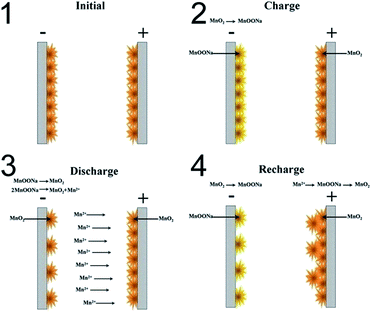
According to the analysis above, a working mechanism of the MnO2 based symmetric supercapacitor was developed and is exhibited in Fig. 7. In the charging process, MnO2 on the positive electrode shows no change, while MnO2 on the negative electrode is reduced to Mn3+ compounds which enlarges the voltage, and some of these compounds are converted to soluble Mn2+ ions. These Mn2+ ions migrate to the positive electrode through the electrolyte by with the help of the electrical field force. In the recharging process, these Mn2+ ions in the electrolyte near the positive electrode are oxidized to MnO2 on the positive electrode, thus achieving a migration of mass from the negative to the positive electrode. The pristine MnO2 on the positive electrode shows no large change but is only being oxidized to complete 4+ valences in the charging process. As a result, in the cyclic charging/discharging process of the MnO2 based symmetric supercapacitor, a new layer of MnO2 is coated on the pristine MnO2 layer of the positive electrode, and the mass of MnO2 on the negative electrode becomes less and less.
Conclusions
In summary, a pseudocapacitive symmetric supercapacitor based on a MnO2 electrode only utilized the active materials on the negative electrode for the reversible redox reaction, thus its material utilization is lower than that of EDLCs. Furthermore, MnO2 on the negative electrode can migrate onto the positive electrode through the diffusion of Mn2+ in the electrolyte, which induces a loss of mass from the negative electrode and the capacitance fading of the symmetric supercapacitor. These results reveal that the capacitance of the MnO2 based symmetric supercapacitor is largely limited by the electrochemical charging/discharging mechanism. Moreover, these results should be of interest to researchers for improving the stability of the negative electrode for enhancing the cyclic lifetime of the device.Acknowledgements
This work was supported by the National Science Foundation of China (No. 21203238), the National Basic Research Program (No. 2011CB932600-G), and the Knowledge Innovation Program (KJCX2.YW.M12) of the Chinese Academy of Sciences.References
- S. Chu and A. Majumdar, Nature, 2012, 488, 294 CrossRef CAS PubMed.
- B. Dunn, H. Kamath and J. M. Tarascon, Science, 2011, 234, 928 CrossRef PubMed.
- D. Larcher and J. M. Tarascon, Nat. Chem., 2015, 7, 19 CrossRef CAS PubMed.
- P. Simon and Y. Gogotsi, Nat. Mater., 2008, 7, 845 CrossRef CAS PubMed.
- J. R. Miller and P. Simon, Science, 2008, 321, 651 CrossRef CAS PubMed.
- P. Simon, Y. Gogotsi and B. Dunn, Science, 2014, 343, 1210 CrossRef CAS PubMed.
- X. Zhao, B. M. Sánchez, P. J. Dobson and P. S. Grant, Nanoscale, 2011, 3, 839 RSC.
- S. Liu, S. Sun and X. Z. You, Nanoscale, 2014, 6, 2037 RSC.
- X. Xia, Y. Zhang, D. Chao, C. Guan, Y. Zhang, L. Li, X. Ge, I. M. Bacho, J. Tu and H. J. Fan, Nanoscale, 2014, 6, 5008 RSC.
- X. Rui, H. Tan and Q. Yan, Nanoscale, 2014, 6, 9889 RSC.
- G. A. Snook, P. Kao and A. S. Best, J. Power Sources, 2011, 196, 1 CrossRef CAS.
- Y. Yin, C. Liu and S. Fan, J. Phys. Chem. C, 2012, 116, 26185 CAS.
- Z. Niu, P. Luan, Q. Shao, H. Dong, J. Li, J. Chen, D. Zhao, L. Cai, W. Zhou, X. Chen and S. Xie, Energy Environ. Sci., 2012, 5, 8726 CAS.
- J. Benson, I. Kovalenko, S. Boukhalfa, D. Lashmore, M. Sanghadasa and G. Yushin, Adv. Mater., 2013, 25, 6625 CrossRef CAS PubMed.
- G. Meng, C. Liu, L. Chen, C. Hu and S. Fan, Nano Lett., 2010, 10, 4025 CrossRef PubMed.
- Y. Gao, H. Jin, Q. Lin, X. Li, M. M. Tavakoli, S. F. Leung, W. M. Tang, L. Zhou, H. Lai, W. Chan and Z. Fan, J. Mater. Chem. A, 2015, 3, 10199 CAS.
- Y. He, W. Chen, X. Li, Z. Zhang, J. Fu, C. Zhao and E. Xie, ACS Nano, 2013, 7(1), 174 CrossRef CAS PubMed.
- L. Yuan, X.-H. Lu, X. Xiao, T. Zhai, J. Dai, F. Zhang, B. Hu, X. Wang, L. Gong, J. Chen, C. Hu, Y. Tong, J. Zhou and Z. L. Wang, ACS Nano, 2012, 6(1), 656 CrossRef CAS PubMed.
- X. Lang, A. Hirata, T. Fujita and M. Chen, Nat. Nanotechnol., 2011, 6, 232 CrossRef CAS PubMed.
- W. Chen, R. B. Rakhi, L. Hu, X. Xie, Y. Cui and H. N. Alshareef, Nano Lett., 2011, 11, 5165 CrossRef CAS PubMed.
- Y. Cheng, S. Lu, H. Zhang, C. V. Varanasi and J. Liu, Nano Lett., 2012, 12, 4206 CrossRef CAS PubMed.
- L. Hu, W. Chen, X. Xie, N. Liu, Y. Yang, H. Wu, Y. Yao, M. Pasta, H. N. Alshareef and Y. Cui, ACS Nano, 2011, 5(11), 8904 CrossRef CAS PubMed.
- Y. Qian, R. Liu, Q. Wang, J. Xu, D. Chen and G. Shen, J. Mater. Chem. A, 2014, 2, 10917 CAS.
- X. Zhou, A. Wang, Y. Pan, C. Yu, Y. Zou, Y. Zhou, Q. Chen and S. Wu, J. Mater. Chem. A, 2015, 3, 13011 CAS.
- Q. Wang, X. Wang, B. Liu, G. Yu, X. Hou, D. Chen and G. Shen, J. Mater. Chem. A, 2013, 1, 2468 CAS.
- W. Yang, Z. Gao, J. Ma, X. Zhang, J. Wang and J. Liu, J. Mater. Chem. A, 2014, 2, 1448 CAS.
- D. Guo, Y. Luo, X. Yu, Q. Li and T. Wang, Nano Energy, 2014, 8, 174–182 CrossRef CAS.
- Z.-Y. Yu, L.-F. Chen and S.-H. Yu, J. Mater. Chem. A, 2014, 2, 10889 CAS.
- J. Zhao, J. Chen, S. Xu, M. Shao, D. Yan, M. Wei, D. G. Evans and X. Duan, J. Mater. Chem. A, 2013, 1, 8836 CAS.
- W. Wei, X. Cui, W. Chen and D. G. Ivey, Chem. Soc. Rev., 2011, 40, 1697 RSC.
- M. Huang, X. L. Zhao, F. Li, L. L. Zhang and Y. X. Zhang, J. Power Sources, 2015, 277, 36 CrossRef CAS.
- M. Huang, R. Mi, H. Liu, F. Li, X. L. Zhao, W. Zhang, S. X. He and Y. X. Zhang, J. Power Sources, 2014, 269, 760 CrossRef CAS.
- G. Hu, C. Li and G. Gong, J. Power Sources, 2010, 195, 6977 CrossRef CAS.
- Y. Jin, H. Chen, M. Chen, N. Liu and Q. Li, ACS Appl. Mater. Interfaces, 2013, 5, 3408 CAS.
- W. Chen, R. B. Rakhi, Q. Wang, M. N. Hedhili and H. N. Alshareef, Adv. Funct. Mater., 2014, 24(21), 3130 CrossRef CAS.
- J. Yan, A. Sumboja, X. Wang, C. Fu, V. Kumar and P. S. Lee, Small, 2014, 10(17), 3568 CrossRef CAS PubMed.
- C. Xu, C. Wei, B. Li, F. Kang and Z. Guan, J. Power Sources, 2011, 196, 7854 CrossRef CAS.
- M. Toupin, T. Brousse and D. Belanger, Chem. Mater., 2004, 16, 3184 CrossRef CAS.
- W. Wei, X. Cui, W. Chen and D. G. Ivey, J. Power Sources, 2009, 186, 543 CrossRef CAS.
- W. Wei, X. Cui, W. Chen and D. G. Ivey, Electrochim. Acta, 2009, 54, 2271 CrossRef CAS.
- S. C. Pang, M. A. Anderson and T. W. Chapman, J. Electrochem. Soc., 2000, 147(2), 444 CrossRef CAS.
| This journal is © The Royal Society of Chemistry 2017 |

