DOI:
10.1039/C6RA25009B
(Paper)
RSC Adv., 2017,
7, 9854-9861
Fabrication and characterization of electrospun feather keratin/poly(vinyl alcohol) composite nanofibers
Received
10th October 2016
, Accepted 12th January 2017
First published on 2nd February 2017
Abstract
Feathers, which contain more than 90% of keratin, are valuable natural protein resources. Moreover, recycling waste feathers to develop biomaterials contributes to environmental protection. The aim of this study was to fabricate and characterize both random and aligned feather keratin (FK)/PVA composite nanofibers through an electrospinning process. The morphology, molecular interaction, crystallization behavior, and tensile properties of the nanofibers were investigated. The electrospinning process appeared stable and successful for solutions containing no more than 40 wt% of FK. Smooth and bead-free FK/PVA random nanofibers were obtained for all the experimental samples. The fiber average diameter decreased for the random nanofibers and the degree of fiber orientation increased for the aligned nanofibers as the FK content increased. The crystallinity of the nanofibers reduced with the incorporation of FK but the orientation of nanofibers was favorable to crystallization. Random nanofibers exhibited an increased tensile strength when the FK to PVA ratio increased. Tensile strength and elongation at break in the direction of the aligned fibers were improved compared to the random nanofibers at the same FK content. This work demonstrates the potential of expanding the application of nanofiber-based products in the biomaterial field.
1 Introduction
Electrospinning is a material-processing method widely used in the fabrication of polymeric nanofibers (NFs) by depositing a charged polymer jet onto a grounded collector. Due to their specific structural characteristics and functional properties, the nanofibers have shown great potential in various applications, including wound dressing, drug delivery, vascular tissue engineering, heavy metal ion adsorption, and antimicrobial active packaging.1–5 The natural polymers have cell-binding sites and biomolecular signatures that can mimic natural tissue. While the synthetic materials usually have good mechanical properties and limited cell affinity compared to the natural polymers. Therefore, in recent years the combination of natural and synthetic polymers for the production of nanofibers by electrospinning has gained increased attention. Shalumon et al.6 successfully electrospun chitosan (CS) together with poly(e-caprolactone) (PCL) into nanofibers from a novel solvent mixture composed of formic acid and acetone. The authors demonstrated that fibers obtained from a solution containing 1% CS and 8% PCL at a 1![[thin space (1/6-em)]](https://www.rsc.org/images/entities/char_2009.gif) :1 ratio resulted in slightly beaded fibers presenting a diameter of 116 ± 27 nm. In contrast, they obtained fine nanofibers exhibiting a diameter of 102 ± 24 nm when they used a 1:3 ratio composition. Besides, Vega-Lugo et al.7 studied the positive effects of poly(ethylene oxide) (PEO) on the electrospinning of whey protein isolate (WPI) solutions under different pH conditions, and revealed that the electrospinning–enabling properties of PEO on aqueous WPI solutions were attributed to physical chain entanglement between the two polymers, rather than specific polymer–polymer interactions. Moreover, Cho et al.8 found that the diameter and mechanical strength of the electrospun soy protein isolate (SPI)/poly(vinyl alcohol) (PVA) hybrid nanofibers decreased gradually as the SPI content increased, but the biodegradation rate of the hybrid nanofibers increased with the incorporation of SPI.
:1 ratio resulted in slightly beaded fibers presenting a diameter of 116 ± 27 nm. In contrast, they obtained fine nanofibers exhibiting a diameter of 102 ± 24 nm when they used a 1:3 ratio composition. Besides, Vega-Lugo et al.7 studied the positive effects of poly(ethylene oxide) (PEO) on the electrospinning of whey protein isolate (WPI) solutions under different pH conditions, and revealed that the electrospinning–enabling properties of PEO on aqueous WPI solutions were attributed to physical chain entanglement between the two polymers, rather than specific polymer–polymer interactions. Moreover, Cho et al.8 found that the diameter and mechanical strength of the electrospun soy protein isolate (SPI)/poly(vinyl alcohol) (PVA) hybrid nanofibers decreased gradually as the SPI content increased, but the biodegradation rate of the hybrid nanofibers increased with the incorporation of SPI.
Among the numerous natural polymers available, keratin is considered as one of the most abundant proteins in nature and can be used in various medical applications due to its biocompatibility and biodegradability.9–11 In addition, the poultry industry generates important annual volumes of by-produced feathers,12,13 representing a significant resource as they contain more than 90% in weight of keratin.14 Unfortunately, most of the feathers are discarded as solid waste in landfill sites without any pretreatment, causing severe environmental pollution. Therefore, recycling and utilizing feather keratin (FK) for the production of biomaterials could also contribute to the protection of the environment.
To date, many studies reported on electrospun nanofibers containing keratin from hair and wool, and the keratin used in these researches was generally extracted by a reduction method employing sodium metabisulfite or 2-mercaptoethanol.3,15–19 In the present study, feather keratin (FK) was extracted by partially oxidizing feathers with peracetic acid. The resulting FK was easily dispersed in water but could not be directly used for electrospinning due to the lack of sufficient entanglement or interactions. To overcome this issue, considering the hydrophilicity of partially oxidized keratin, we suggested blending FK with a water-soluble electrospinnable polymer, namely polyvinyl alcohol (PVA). It was expected that the affinity between PVA and FK would facilitate the fiber formation during the spinning process. The main objective of this work was to evaluate the feasibility of using FK and PVA from blended aqueous solutions to produce both random and aligned electrospun composite nanofibers by altering the rotating speed of the collector. Morphologies of the composite nanofibers and the interaction between FK and PVA were investigated by scanning electron microscopy (SEM) and Fourier transform infrared (FT-IR) spectroscopy. Thermal behaviors and tensile properties of the fibers with different ratios of FK and PVA were evaluated.
2 Experimental
2.1 Materials
The chicken feathers were collected from markets in Guangzhou city. Poly(vinyl alcohol) (PVA, degree of alcoholysis: 87–89%) was purchased from Aladdin industrial corporation (China). Peracetic acid was purchased from Tianjin Damao chemical reagents factory (China). All the chemicals were used without further purification. Double-distilled water was used as solvent.
2.2 Extraction of feather keratin
The chicken feathers collected from markets were firstly immersed in ethanol for 24 h, and then thoroughly washed with detergents and water respectively. Then the wet feathers were dried in an oven at 60 °C for 48 h. Next, FK was extracted according to the literature reported by Timmons et al. with slight modifications.20,21 The cleaned chicken feathers were added to a 16 wt% solution of freshly prepared peracetic acid (1:12, w/w), and the extraction was performed at 60 °C for 100 min under constant stirring. The resultant solution were passed through a nylon mesh (150 and 75 μm, respectively). The filtrates were subsequently dialyzed in dialysis tubes (Oso-T8280, 8000-14000, Union Carbide, USA) against distilled water at room temperature for a week, and the water was changed every 12 hours. The desired FK precipitated through dialysis. After filtration, washing and drying, FK was ground and stored in a sealed bag until further usage.
2.3 Preparation of polymer solutions for electrospinning
Polymer solutions for electrospinning were prepared by dissolving FK and PVA at different weight ratios in distilled water and maintaining the total weight of polymers in solution constant at 14 wt%. FK powders were dispersed in water and completely dissolved by slowly dropping a 1 mol L−1 NaOH solution under continuous stirring at 50 °C. Different weight ratios of PVA was added to the resulting FK solution and the pH value of the mixture was adjusted to 9.5 using a 0.1 mol L−1 NaOH solution. A series of FK/PVA solutions labeled FK0PVA10, FK1PVA9, FK2PVA8, FK3PVA7, and FK4PVA6 were prepared with FK:PVA weight ratios of 0:10, 1:9, 2:8, 3:7, and 4:6, respectively.
2.4 Characterization of the polymer solutions
The viscosity of the polymer solutions was determined by a digital viscometer (SNB-2, Shanghai Precision & Scientific Instrument Co. Ltd., China) at 25 °C. In addition, electrical conductivity of the solutions was measured by a digital conductivity meter (DDS-11A, Shanghai Leici-Chuangyi Instrument and Meter Co. Ltd., China).
2.5 Electrospinning of FK/PVA composite nanofibers
FK/PVA nanofibers were prepared using a electrospinning machine (ET-2535DC, Beijing Yongkang Leye Technology Development Co. Ltd., China) and the schematic representation is showed in Fig. 1. 10 mL of each polymer solution was loaded into a syringe equipped with a 22-gauge blunt-tipped needle. A rotating cylindrical mandrel wrapped with an aluminum foil was used as the fiber collector. The electrospinning process was performed at 9 kV applied voltage, 10 cm needle tip-to-collector distance, and 0.5 mL h−1 flow rate. The rotating speed of the collector was 80 rpm for the random nanofibers (RNFs) and 2800 rpm for aligned the nanofibers (ANFs).
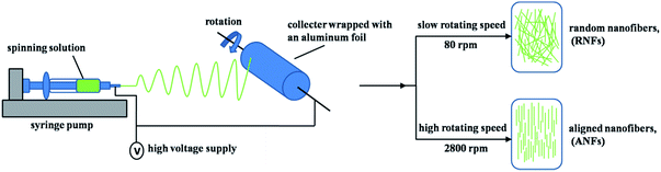 |
| | Fig. 1 Schematic representation of the applied electrospinnig process. | |
2.6 Scanning electron microscopy (SEM)
The morphologies of the electrospun nanofibers were observed by scanning electron microscopy (EVO 18, Carl Zeiss, Germany) at 10 kV accelerating voltage. The average fiber diameter and diameter distribution were determined by measuring 100 fibers selected randomly from each sample.
2.7 Attenuated total reflectance infrared spectroscopy (ATR-FTIR)
The FTIR spectra of the nanofiber samples were recorded with an infrared spectrometer (spectrum 100, Perkin-Elmer, USA), using attenuated total reflectance mode (ATR). A range of wavenumber from 4000–650 cm−1 and accumulation of 8 scans were used for each analysis.
2.8 Differential scanning calorimetry (DSC)
The thermal properties of the electrospun nanofibers were performed using a differential scanning calorimeter (DSC1, Mettler Toledo, Switzerland). One sample of each formulation was analyzed by being heated from 25 to 250 °C at a heating rate of 10 °C min−1.
2.9 Tensile properties
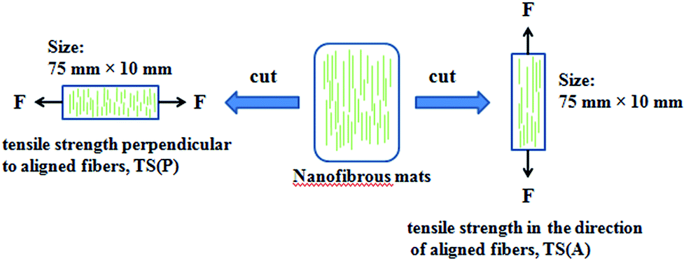
The tensile properties of the nanofibers including tensile strength (TS) and elongation at break (EAB) were determined using a universal testing machine (CMT6503, Shenzhen MTS Test Machine Company Ltd., China). A strain rate of 10 mm min−1 was used throughout the experiment, according to the ASTM standard D638. The nanofibers were cut into a size of 75 mm × 10 mm and the thicknesses of the samples were measured by a micrometer. Three replications of each formulation were performed and average values of the measurements were used. The schematic representation of the tensile performance test for aligned fibers is displayed in Fig. 2.
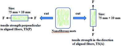 |
| | Fig. 2 Schematic representation of the tensile performance test applied on the aligned fibers. | |
3 Results and discussion
3.1 Physicochemical properties of the polymer solutions
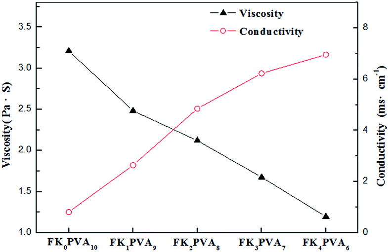
It has been wildly approved that the physicochemical properties of an electrospinning solution such as viscosity and conductivity play a decisive role in the formation of continuous fibers.22–24 These parameters determine the morphology and size of the fibers. The solution properties of the various FK/PVA compositions are represented in Fig. 3. During electrospinning, an appropriate viscosity of the solution is essential for the formation of fibers. A viscosity below a minimum threshold would form beads, while one above a maximum limit would not permit to achieve electro ejection. It could be observed that at a fixed total polymer concentration of 14 wt%, the pure PVA solution (FK0PVA10) presented the highest viscosity (3.210 Pa s). The viscosity of the electrospinning solution decreased when the FK proportion increased. The lowest viscosity of 1.195 Pa s was achieved with sample FK4PVA6.
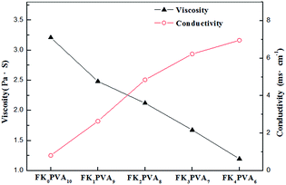 |
| | Fig. 3 Viscosity, and conductivity of the spinning solution as function of FK/PVA ratio. | |
Electrical conductivity determines the ability to transfer charge to the surface of the pendant droplet, and it directly affects the buildup of an electrostatic repulsion force that is critical to initiate jetting. As shown in Fig. 3, conductivity increased as the amount of FK increased inside the blend solution. This observation could be attributed to the presence of many polar groups such as amide and carboxylic groups existing in keratin, as reported for the case of keratin/poly(lactic acid) blends in the literature.25 The results indicated that the variation of conductivity with the increasing FK content was not linear, which could be due to the existence of contact resistance between both polymers.23
3.2 Morphologies
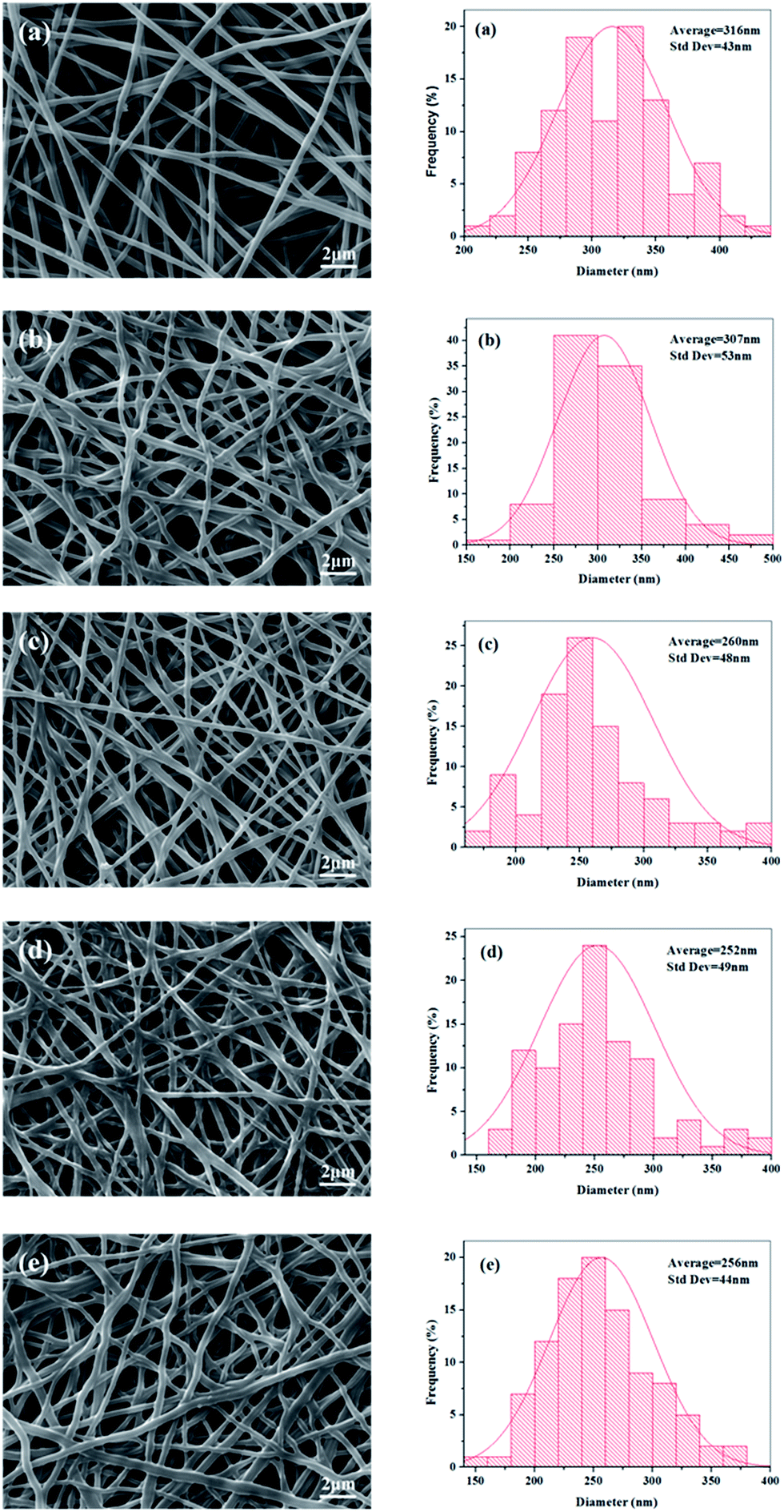
The electrospinning process appeared stable and successful for all the experimental groups at a total polymer concentration of 14 wt%. The SEM images of electrospun random nanofibers (RNFs) prepared at different ratio of FK and PVA are displayed in Fig. 4. The RNFs exhibited common features consisting of a porous and fibrous structure. The fibers were smooth, bead-free, and randomly oriented for all the PVA fibers and FK/PVA fibers. These observations implied that no obvious phase separation between FK and PVA occurred during the electrospinning process, supporting the favorable compatibility between the two phases. However, the addition of FK led to modifications in the surface morphologies of the fibers. Indeed, pure PVA nanofibers (RNFs–FK0PVA10) were straight with circular cross sections, while FK-incorporated RNFs exhibited more curved and belt-like morphologies and reduced inter-fiber space. These belt-like morphologies, which were also observed in the electrospinning of wool keratin in formic acid at 20 wt% and fibroin-based nanofibers from solutions presenting relatively high viscosity (about 0.5 Pa s),26,27 could be the consequence of an uneven evaporation of the solvent from the skin and the core of the jet during drawing, causing the collapse of the filament.28 Moreover, branching of the fibers appeared in the FK/PVA RNFs, which could be attributed to the uneven distribution of the charge carried by the jets, caused by jet elongation/bending and solvent evaporation. Indeed, jets could reduce their local surface charge density by ejecting smaller jets from the surface of the primary jets or by splitting into multiple smaller jets.22 The conductivity of the electrospinning solutions increased as the content of FK increased (Fig. 3), potentially leading to more uneven jet surface charge distribution, which consequently resulted in higher probability of jet branching.
 |
| | Fig. 4 SEM images and diameter distributions of electrospun random nanofibers (RNFs) with various blending ratios: (a) FK0PVA10, (b) FK1PVA9, (c) FK2PVA8, (d) FK3PVA7, (e) FK4PVA6. | |
We recorded the micrographs of the RNFs prepared from various blending FK/PVA ratios by SEM and analyzed their diameter distributions as illustrated in Fig. 4. The results showed that pure PVA nanofibers (NFs–FK0PVA10) presented the highest fiber average diameter and the lowest standard deviation (316 ± 43 nm) among all the tested fibers. Upon the addition of FK into the spinning solutions, we could observe a general trend of decreased average fiber diameter and wide distribution. The viscosity of the solutions decreased with the incorporation of FK, thus the interactions and entanglements between molecular chains were weakened. Furthermore, the conductivity increased as the ratio of FK to PVA increased. As a consequence, the jets generated by the blend solutions became less resistant to the stretching repulsive forces from the charge during the electrospinning process, resulting in the decrease in diameter of the composite electrospun fibers. Similar results were also obtained in the study of human hair keratin/polyurethane nanofibrous mats and soy protein isolate/PVA hybrid nanofibers.8,15
It should be pointed out that to obtain satisfactory fibers, the ratio of FK in the blend solution had to be less than or equal to 40 wt% (FK4PVA6). Electrospinning was not successful when the FK content increased further. Poor morphologies of fibers exhibiting many large beads were obtained and the fibers were difficult to handle (data not presented). Similarly, Yen et al.29 also found that the fibrous structure was not constructed by electrospinning keratin/fibroin blend solutions when the keratin content exceeded 35%. Therefore, only electrospun fibers from solutions containing no more than 40 wt% of FK were further considered in the present study.
The aligned nanofibers (ANFs) were reported to be able to instruct the cultured cells directionally growth, resulting in the elongation and alignment of cells along the major axis of the nanofibers.30–32 Thus the orientation of nanofibers provide nanofibers a broad range of applications in the biomaterial field. Several researchers have found out that the orientation of fibers could be modulated by the rotational speed of the collector and that by increasing the rotating rate, more uniform fibers were produced.33,34 Fig. 5 displays the SEM images of electrospun ANFs which were collected by rotating cylindrical mandrel at the speed of 2800 rpm. It can be seen that ANFs were fabricated by the higher rotating speed of collector, and the degree of the ANFs orientation increased as the FK content increased in the blends. In addition, it was interesting that when the weight fraction of FK in the solution was higher than 20 wt% (FK3PVA7 and FK4PVA6), the ANFs were found to be densely packed as the interstice between the fibers reduced. This result was probably due to the plasticizing effect of FK during the electrospinning process, facilitating orientation and flow of PVA by uncoiling and wrapping around PVA chains. A similar contribution was reported for pullulan in the pullulan/API electrospun fibers and PEO in the PEO/chitosan blends.24,35
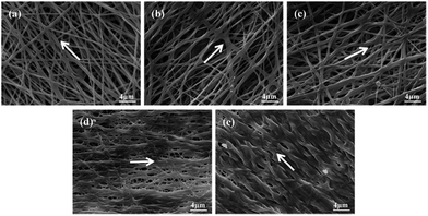 |
| | Fig. 5 SEM images of electrospun aligned nanofibers (ANFs) with various blending ratios: (a) FK0PVA10, (b) FK1PVA9, (c) FK2PVA8, (d) FK3PVA7, (e) FK4PVA6. Notes: the white arrow indicates the orientation of the ANFs. | |
3.3 FT-IR spectra
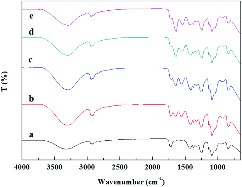
The molecular interactions between FK and PVA, together with the secondary structure of the keratin in the composite nanofibers were investigated by FTIR spectroscopy. As shown in Fig. 6, the characteristic absorption band of PVA, attributed to the O–H stretching vibration, was observed at 3319 cm−1 in the spectra of FK0PVA10.36 When FK was added into the spinning system, spectra of the resultant composite nanofibers exhibited new absorption peaks of amide I (C![[double bond, length as m-dash]](https://www.rsc.org/images/entities/char_e001.gif) O stretching vibration) and amide II (N–H bending and C–H stretching vibration), which were located at 1700–1600 and 1580–1480 cm−1, respectively.37 These bands confirmed the introduction of keratin inside the composite nanofibers. It was found that the wavenumbers of amide I and amide II shifted to a lower wavenumber and the intensities gradually increased as the proportion of FK increased. In addition, the characteristic absorption band of PVA at 3319 cm−1 also shifted to a lower wavenumber in the composite nanofibers. These results strongly indicated that the main interaction between FK and PVA in the fibers would be through the formation of hydrogen bonds, which improved the electrospinnability of FK/PVA composite nanofibers.
O stretching vibration) and amide II (N–H bending and C–H stretching vibration), which were located at 1700–1600 and 1580–1480 cm−1, respectively.37 These bands confirmed the introduction of keratin inside the composite nanofibers. It was found that the wavenumbers of amide I and amide II shifted to a lower wavenumber and the intensities gradually increased as the proportion of FK increased. In addition, the characteristic absorption band of PVA at 3319 cm−1 also shifted to a lower wavenumber in the composite nanofibers. These results strongly indicated that the main interaction between FK and PVA in the fibers would be through the formation of hydrogen bonds, which improved the electrospinnability of FK/PVA composite nanofibers.
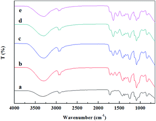 |
| | Fig. 6 FTIR spectra of the RNFs with various blending ratios: (a) RNFs–FK0PVA10, (b) RNFs–FK1PVA9, (c) RNFs–FK2PVA8, (d) RNFs–FK3PVA7, (e) RNFs–FK4PVA6. | |
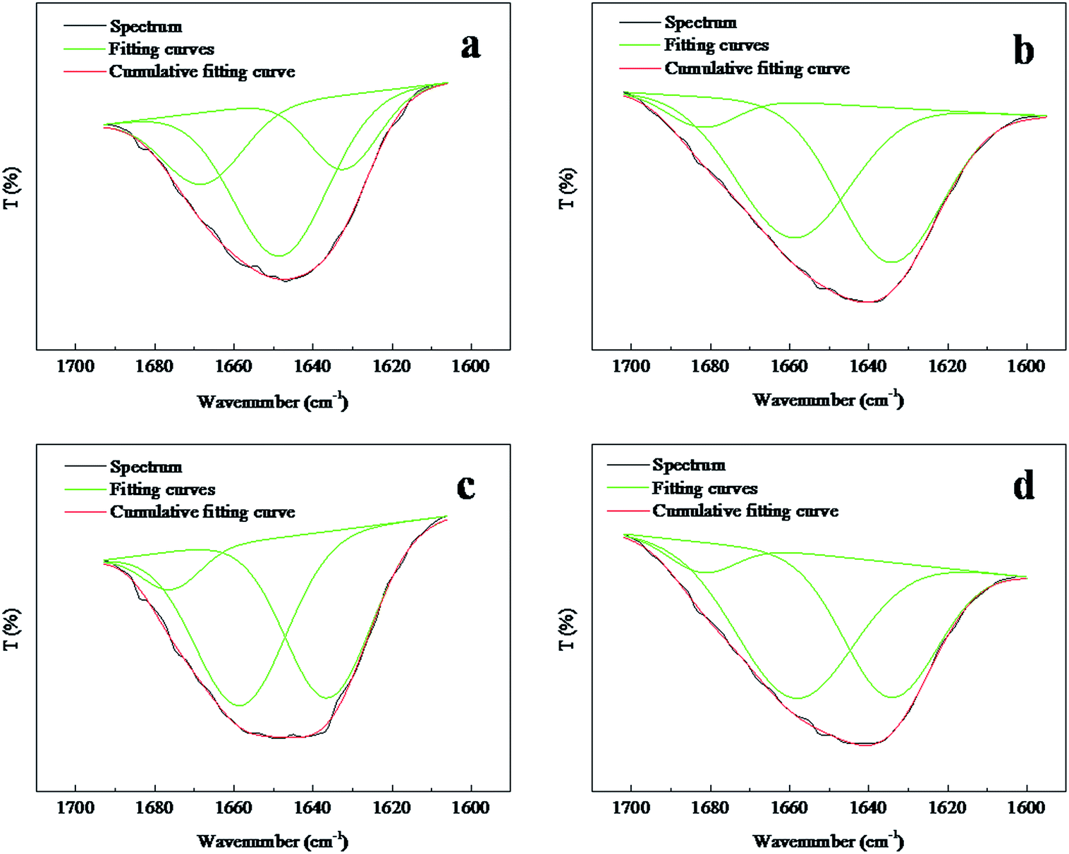
The amide I (1700–1600 cm−1) band is known to be especially sensitive to the secondary structure of the proteins.38 On the basis of the above spectral analysis, the position of the amide I transmission band was not disturbed by the absorption peaks generated by PVA. Therefore, the amide I band could characterize the secondary structure of the keratin inside the composite nanofibers. A closer look into the region of 1700–1600 cm−1 for both selected random and aligned FK/PVA nanofibers are presented in Fig. 7. The absorption band at ∼1650 cm−1 is characteristic of α-helix structures in keratin chains, whereas the peaks between 1610–1633 cm−1 are attributed to β-sheet structures.39–42 The areas of the peak's corresponding structure were calculated and summarized in Table 1. The results indicated that the ANFs–FK4PVA6 showed a lower band area of the β-sheet structure and a higher area of the α-helix structure, compared to the ANFs–FK1PVA9. This observation suggested that the molecular chains of keratin could be hindered by the PVA chains during the process of fiber alignment. A similar effect was reported for the keratin/poly(lactic acid) nanofiber mats.25 However, the contrary behavior was observed for the α-helix and β-sheet structure variation of the random nanofibers.
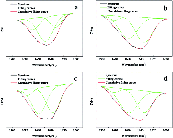 |
| | Fig. 7 Amide I region spectra of random and aligned nanofibers: (a) RNFs–FK1PVA9, (b) RNFs–FK4PVA6, (c) ANFs–FK1PVA9, (d) ANFs–FK4PVA6. | |
Table 1 Characteristics of the amide I bands of FK/PVA nanofibers
| Samples |
Secondary structure |
Area (%) |
| RNFs–FK1PVA9 |
α-Helix |
57 |
| β-Sheet |
20 |
| RNFs–FK4PVA6 |
α-Helix |
46 |
| β-Sheet |
48 |
| ANFs–FK1PVA9 |
α-Helix |
47 |
| β-Sheet |
46 |
| ANFs–FK4PVA6 |
α-Helix |
54 |
| β-Sheet |
40 |
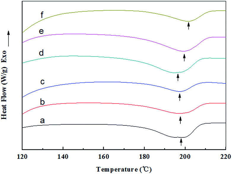
3.4 DSC analysis
The DSC curves together with the related peak temperatures and enthalpy values (ΔHm) of the random and aligned nanofibers are presented in Fig. 8 and Table 2. The endothermic peak observed at about 200 °C for all the samples was attributed to the crystalline melting (Tm) of the nanofibers, and the peak area represented the crystallinity of the nanofibers.43 The RNFs exhibited a melting peak (Tm) at approximately 198 °C, and the ΔHm value decreased from 35.29 (RNFs–FK0PVA10) to 18.81 J g−1 (RNFs–FK4PVA6) after adding 40 wt% of keratin. This result suggested that the crystallinity of the nanofibers reduced upon the incorporation of FK. Similar observation was reported for the case of keratin/PVA films by the casting process.44 The ΔHm values of the ANFs were markedly higher than that of the RNFs when compared at the same amount of keratin, indicating that the orientation of the nanofibers was favorable to crystallization.
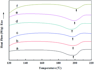 |
| | Fig. 8 DSC curves of random and aligned nanofibers: (a) RNFs–FK0PVA10, (b) RNFs–FK1PVA9, (c) RNFs–FK4PVA6, (d) ANFs–FK0PVA10, (e) ANFs–FK1PVA9, (f) ANFs–FK4PVA6. | |
Table 2 Peak temperatures and enthalpy values of the DSC analysis
| Samples |
Tm (°C) |
ΔHm (J g−1) |
| RNFs–FK0PVA10 |
198.55 |
35.29 |
| RNFs–FK1PVA9 |
197.20 |
28.45 |
| RNFs–FK4PVA6 |
197.18 |
18.81 |
| ANFs–FK0PVA10 |
194.59 |
41.79 |
| ANFs–FK1PVA9 |
198.89 |
39.47 |
| ANFs–FK4PVA6 |
201.23 |
24.61 |
3.5 Tensile properties
The results of the tensile tests in terms of tensile strength (TS) and elongation at break (EAB) of the nanofibers were summarized in Table 3 and 4. In the literature, different results are reported on the effect of protein content on the tensile properties of composite nanofibers. Li et al.45 reported that PCL/keratin composite nanofibrous mats showed an enhanced tensile strength when keratin was added. This observation was explained by the compatibility of keratin and PCL in a limited range or by the rigid-filler role of hard keratin.46 While Cho et al.8 found that the increase in the soy protein isolate (SPI) content induced the sharp reduction of both the breaking strength and elongation of the SPI/PVA hybrid nanofibers. This result corresponded with the fact that SPI protein could not produce strong fibers due to its globular structure. In the present study, the TS values of the FK/PVA composite RNFs were higher than that of the pure PVA fibers (RNFs–FK0PVA10). The increased TS was naturally coupled with a decrease of extensibility (EAB value). Reinforced strength was possibly related to the favorable compatibility and strong interactions between FK and PVA (Fig. 4 and 6), as well as the increased content of β-sheet structure in the keratin at higher FK content (Table 1). It is known that β-sheet structure could provide a more rigid structure than α-helix, and lead to high strength and small displacement characteristic of the materials.25
Table 3 Tensile properties of the RNFs
| Samples |
TS (MPa) |
EAB (%) |
| RNFs–FK0PVA10 |
5.59 ± 1.18 |
50.17 ± 6.05 |
| RNFs–FK1PVA9 |
6.15 ± 2.12 |
34.33 ± 7.09 |
| RNFs–FK2PVA8 |
6.87 ± 0.38 |
23.17 ± 5.97 |
| RNFs–FK3PVA7 |
6.82 ± 0.92 |
17.83 ± 5.35 |
| RNFs–FK4PVA6 |
6.71 ± 0.56 |
14.33 ± 3.51 |
Table 4 Tensile properties of the ANFs
| Samples |
TS (MPa) |
EAB (%) |
| In the direction of aligned fibers |
Perpendicular to aligned fibers |
In the direction of aligned fibers |
Perpendicular to aligned fibers |
| ANFs–FK0PVA10 |
8.54 ± 0.95 |
1.52 ± 0.28 |
154.17 ± 12.57 |
42.33 ± 4.51 |
| ANFs–FK1PVA9 |
8.93 ± 1.58 |
1.18 ± 0.33 |
77.00 ± 11.63 |
33.83 ± 7.82 |
| ANFs–FK2PVA8 |
9.44 ± 1.10 |
0.95 ± 0.18 |
87.83 ± 16.00 |
31.00 ± 4.36 |
| ANFs–FK3PVA7 |
10.53 ± 1.35 |
1.28 ± 0.16 |
110.67 ± 14.57 |
21.67 ± 6.51 |
| ANFs–FK4PVA6 |
10.71 ± 1.36 |
1.31 ± 0.31 |
111.10 ± 15.70 |
17.50 ± 3.77 |
With respect to the aligned nanofibers, the TS in the direction of the aligned fibers was higher and the TS perpendicular to the aligned fibers was lower, compared to the RNFs prepared at the same FK ratio. Moreover, extensibility (EAB value) in the direction of the aligned fibers was also significantly improved. These results could be explained by the orientation of the fibers, which is represented by a white arrow in Fig. 5.
4 Conclusion
Feather keratin (FK) extracted by partial oxidization using peracetic acid was blended with PVA at different weight fraction, while maintaining the total weight of polymer in the solution constant (14 wt%). The viscosity decreased and the electrical conductivity increased when the weight fraction of keratin in the blend solutions increased. The electrospinning process appeared stable and successful for FK/PVA blend solutions containing no more than 40 wt% of FK. Both random and aligned composite nanofibers (RNFs and ANFs) were fabricated by changing the rotating speed of the collector. All the nanofibers were found to be smooth and bead-free with favorable compatibility between FK and PVA. The FK/PVA RNFs exhibited a lower fiber average diameter and higher standard deviation compared to the pure PVA fibers. The degree of fiber orientation increased with the increase of the FK content in the blends for the ANFs. Formation of hydrogen bonds between the two components was confirmed by FTIR spectroscopy. The crystallinity of the nanofibers reduced with the incorporation of FK but the orientation of nanofibers was favorable to crystallization. The FK/PVA RNFs exhibited an increased tensile strength coupled with a decrease of extensibility when increasing the FK content. Tensile strength and elongation at break in the direction of the ANFs were higher compared to the RNFs at the same FK ratio. Overall, the present work demonstrated the possibility to incorporate FK into nanofibers that have the potential to be applied in the biomaterial field.
Acknowledgements
This work is supported by the National Natural Science Foundation of China (21176269), Science and Technology Plan project of Guangdong Province (2013B010403029), and Higher School Science and Technology Innovation project of Guangdong Province (2013KJCX0102).
Notes and references
- C. S. Ki, E. H. Gang, I. C. Um and Y. H. Park, J. Membr. Sci., 2007, 302, 20–26 CrossRef CAS.
- J. Li, Y. Li, L. Li, A. F. T. Mak, F. Ko and L. Qin, Polym. Degrad. Stab., 2009, 94, 1800–1807 CrossRef CAS.
- H.-L. Zhang, J. Wang, N. Yu and J.-S. Liu, J. Polym. Res., 2014, 21, 329–336 CrossRef.
- M. Boakye, N. Rijal, U. Adhikari and N. Bhattarai, Materials, 2015, 8, 4080 CrossRef.
- D. G. Yu, G. R. Williams, X. Wang, X. K. Liu, H. L. Li and S. W. A. Bligh, RSC Adv., 2013, 3, 4652–4658 RSC.
- K. T. Shalumon, K. H. Anulekha, C. M. Girish, R. Prasanth, S. V. Nair and R. Jayakumar, Carbohydr. Polym., 2010, 80, 413–419 CrossRef CAS.
- A.-C. Vega-Lugo and L.-T. Lim, J. Polym. Sci., Part B: Polym. Phys., 2012, 50, 1188–1197 CrossRef CAS.
- D. Cho, A. N. Netravali and Y. L. Joo, Polym. Degrad. Stab., 2012, 97, 747–754 CrossRef CAS.
- R. Li and D. Wang, J. Appl. Polym. Sci., 2013, 127, 2648–2653 CrossRef CAS.
- Y. W. Wu, C. Y. Han, J. H. Yang, S. X. Jia and S. G. Wang, Surf. Coat. Technol., 2011, 206, 506–510 CrossRef CAS.
- S. Reichl, Biomaterials, 2009, 30, 6854–6866 CrossRef CAS PubMed.
- E. Jin, N. Reddy, Z. Zhu and Y. Yang, J. Agric. Food Chem., 2011, 59, 1729–1738 CrossRef CAS PubMed.
- L. Zhao, H. Zhou and J. Hua, China Leather, 2011, 40, 36–40 CAS.
- N.-B. Song, J.-H. Lee, M. Al Mijan and K. B. Song, LWT–Food Sci. Technol., 2014, 57, 453–460 CrossRef CAS.
- Y. Wang, P. Li, P. Xiang, J. Lu, J. Yuan and J. Shen, J. Mater. Chem. B, 2016, 4, 635–648 RSC.
- J. Fan, T.-D. Lei, J. Li, P.-Y. Zhai, Y.-H. Wang, F.-Y. Cao and Y. Liu, Mater. Des., 2016, 104, 60–67 CrossRef CAS.
- C. Jawun, G. Panthi, L. Yanan, K. Jongwan, C. Su-Hyeong, L. Chohye, P. Mira and K. Hak-Yong, Polymer, 2015, 58, 146–152 CrossRef.
- S. Li and X.-H. Yang, Adv. Mater. Sci. Eng., 2014, 2014, 1–7 Search PubMed.
- A. Aluigi, C. Tonetti, C. Vineis, C. Tonin and G. Mazzuchetti, Eur. Polym. J., 2011, 47, 1756–1764 CrossRef CAS.
- S. F. Timmons, C. R. Blanchard and R. A. Smith, US pat. 006124265A, 2000.
- S. F. Timmons, C. R. Blanchard and R. A. Smith, EP pat. 1033953B1, 2008.
- X. Xu, L. Jiang, Z. Zhou, X. Wu and Y. Wang, ACS Appl. Mater. Interfaces, 2012, 4, 4331–4337 CAS.
- J. Colin-Orozco, M. Zapata-Torres, G. Rodriguez-Gattorno and R. Pedroza-Islas, Food Biophys., 2015, 10, 134–144 CrossRef.
- M. Aceituno-Medina, S. Mendoza, J. M. Lagaron and A. López-Rubio, Food Res. Int., 2013, 54, 667–674 CrossRef CAS.
- S. Isarankura Na Ayutthaya, S. Tanpichai and J. Wootthikanokkhan, J. Polym. Environ., 2015, 23, 506–516 CrossRef CAS.
- A. Aluigi, A. Corbellini, F. Rombaldoni, M. Zoccola and M. Canetti, Int. J. Biol. Macromol., 2013, 57, 30–37 CrossRef CAS PubMed.
- D. H. Baek, C. S. Ki, I. C. Um and Y. H. Park, Fibers Polym., 2007, 8, 271–277 CrossRef CAS.
- S. Koombhongse, W. X. Liu and D. H. Reneker, J. Polym. Sci., Part B: Polym. Phys., 2001, 39, 2598–2606 CrossRef CAS.
- K.-C. Yen, C.-Y. Chen, J.-Y. Huang, W.-T. Kuo and F.-H. Lin, J. Mater. Chem. B, 2016, 4, 237–244 RSC.
- J. Hu, L. L. Tian, M. P. Prabhakaran, X. Ding and S. Ramakrishna, Polymers, 2016, 8, 54–70 CrossRef.
- W. Zhu, F. Masood, J. O'Brien and L. G. Zhang, Nanomedicine: Nanotechnology, Biology and Medicine, 2015, 11, 693–704 CrossRef CAS PubMed.
- K. H. Zhang, C. Y. Wang, C. Y. Fan and X. M. Mo, J. Biomed. Mater. Res., Part A, 2014, 102, 2680–2691 CrossRef PubMed.
- Z. Wei, F. Masood, J. O'Brien and L. G. Zhang, Nanomedicine Nanotechnology Biology & Medicine, 2015, 11, 693–704 Search PubMed.
- N. Zander, J. A. Orlicki, A. M. Rawlett and T. Beebe, Biointerphases, 2010, 5, 149–158 CrossRef CAS PubMed.
- C. Kriegel, K. Kit, D. J. Mcclements and J. Weiss, Polymer, 2009, 50, 189–200 CrossRef CAS.
- M. Park, H. K. Shin, G. Panthi, M. M. Rabbani, A.-M. Alam, J. Choi, H.-J. Chung, S.-T. Hong and H.-Y. Kim, Int. J. Biol. Macromol., 2015, 76, 45–48 CrossRef CAS PubMed.
- F. Selmin, F. Cilurzo, A. Aluigi, S. Franzè and P. Minghetti, Results Pharma Sci., 2012, 2, 72–78 CrossRef PubMed.
- W. K. Surewicz, H. H. Mantsch and D. Chapman, Biochemistry, 1993, 32, 389–394 CrossRef CAS PubMed.
- S. I. N. Ayutthaya, S. Tanpichai, W. Sangkhun and J. Wootthikanokkhan, Int. J. Biol. Macromol., 2016, 85, 585–595 CrossRef PubMed.
- Y. Liu, X. Yu, J. Li, J. Fan, M. Wang, T.-D. Lei, J. Liu and D. Huang, J. Nanomater., 2015, 2015, 1–7 Search PubMed.
- M. Zoccola, A. Aluigi, C. Vineis, C. Tonin, F. Ferrero and M. G. Piacentino, Biomacromolecules, 2008, 9, 2819–2825 CrossRef CAS PubMed.
- A. Aluigi, C. Vineis, A. Varesano, G. Mazzuchetti, F. Ferrero and C. Tonin, Eur. Polym. J., 2008, 44, 2465–2475 CrossRef CAS.
- Y. Nakano, Y. Bin, M. Bando, T. Nakashima, T. Okuno, H. Kurosu and M. Matsuo, Macromol. Symp., 2007, 258, 63–81 CrossRef CAS.
- Y. Dou, B. Zhang, M. He, G. Yin, Y. Cui and I. N. Savina, Polymers, 2015, 7, 580–591 CrossRef CAS.
- Y. Li, Y. Wang, J. Ye, J. Yuan and Y. Xiao, Mater. Sci. Eng., C, 2016, 68, 177–183 CrossRef CAS PubMed.
- J. Lee, G. Tae, Y. H. Kim, I. S. Park, S. H. Kim and S. H. Kim, Biomaterials, 2008, 29, 1872–1879 CrossRef CAS PubMed.
|
| This journal is © The Royal Society of Chemistry 2017 |
Click here to see how this site uses Cookies. View our privacy policy here. 
 Open Access Article
 This Open Access Article is licensed under a Creative Commons Attribution-Non Commercial 3.0 Unported Licence
 a,
Buning Zhangb,
Yao Doua,
Guoqiang Yin*b,
Yingde Cuiac and
Xunjun Chenb
a,
Buning Zhangb,
Yao Doua,
Guoqiang Yin*b,
Yingde Cuiac and
Xunjun Chenb