Role of ion hydration for the differential capacitance of an electric double layer
Received
16th June 2016
, Accepted 21st September 2016
First published on 21st September 2016
Abstract
The influence of soft, hydration-mediated ion–ion and ion–surface interactions on the differential capacitance of an electric double layer is investigated using Monte Carlo simulations and compared to various mean-field models. We focus on a planar electrode surface at physiological concentration of monovalent ions in a uniform dielectric background. Hydration-mediated interactions are modeled on the basis of Yukawa potentials that add to the Coulomb and excluded volume interactions between ions. We present a mean-field model that includes hydration-mediated anion–anion, anion–cation, and cation–cation interactions of arbitrary strengths. In addition, finite ion sizes are accounted for through excluded volume interactions, described either on the basis of the Carnahan–Starling equation of state or using a lattice gas model. Both our Monte Carlo simulations and mean-field approaches predict a characteristic double-peak (the so-called camel shape) of the differential capacitance; its decrease reflects the packing of the counterions near the electrode surface. The presence of hydration-mediated ion–surface repulsion causes a thin charge-depleted region close to the surface, which is reminiscent of a Stern layer. We analyze the interplay between excluded volume and hydration-mediated interactions on the differential capacitance and demonstrate that for small surface charge density our mean-field model based on the Carnahan–Starling equation is able to capture the Monte Carlo simulation results. In contrast, for large surface charge density the mean-field approach based on the lattice gas model is preferable.
1 Introduction
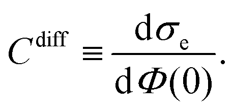
The presence of an electrode in an electrolyte solution changes the way ions are distributed. Mobile ions rearrange so as to screen the charge at the electrode surface, thus forming an electrical double layer (EDL) in this process. The EDL has great importance in biological, colloidal and polyelectrolyte sciences,1–5 surface conductivity,6 renewable energy systems,7,8 new methods for oil recovery,9 and in electrical double layer capacitors, a device that stores electrochemical energy through the EDL.10,11 The electrode is often approximately described by a perfectly planar charged surface, but other geometries have also been taken into account.12 The most simple model of an EDL is a parallel-plate capacitor, where one plate corresponds to the charged surface while the other plate represents the diffuse ion cloud formed by the mobile counter- and co-ions. Based on this, an EDL can be characterized by three quantities: the electrostatic potential at the surface Φ(0), the surface charge density σe, and the differential capacitance Cdiff = dσe/dΦ(0), which embodies the relationship between σe and Φ(0).
The differential capacitance Cdiff is often observed to initially increase and then pass through a maximum as |σe| increases. Yet, no maximum is predicted by the most simple and widely used theoretical model, which is based on the classical Poisson–Boltzmann (PB) theory.13,14 This discrepancy, which has motivated the advancement of theoretical models and the application of computer simulations, appears to be related to two approximations that are inherent in the classical PB theory:15–18 first, it treats the mobile ions as being point-like instead of accounting for their non-vanishing sizes and, second, it ignores the structure of the solvent by assuming a structureless medium of uniform dielectric constant.19
A simple approach to account for the finite size of the mobile ions goes back to Stern,20 who assumed that some of the mobile counterions adsorb onto the flat surface, thus creating a region that separates the charged surface from the diffuse part of the EDL. Stern proposed to treat that region as a planar capacitor with a constant thickness equal to the effective ion radius. The incorporation of steric effects directly into the diffuse ion layer on the basis of a lattice gas model dates back to Bikerman.21 Since then, several other approaches have been developed to include steric effects, such as different modified Poisson–Boltzmann equations,22–24 lattice-based models,25–27 integral equation theories,28–30 equations of state based on liquid-state theory for hard spheres mixtures31–34 and Monte Carlo simulations.35–38
Steric effects render the structure of the EDL ion-specific. However, ion specificity is also manifested by the formation of a hydration shell consisting of ordered water molecules in the vicinity of the mobile ions.39 Previous experimental1,40 and simulation studies41,42 have demonstrated that hydration-mediated ion–ion and ion–surface interactions are soft with a characteristic decay length corresponding to the size of a water molecule and can exhibit oscillatory behavior.43,44 For example, Baimpos et al.45 have observed that, depending on the type of salt and its concentration, the measured force between two mica surfaces becomes oscillatory when the plates approach each other.
Reducing the non-electrostatic ion–ion and ion–surface interaction in an EDL to steric repulsions between hard spheres can therefore not be expected to capture the full scope of ion specificity.46,47 In line with this, some efforts have been made recently to incorporate soft potentials as models for hydration-mediated ion–ion interactions into PB theory.48–50 One approach employs a Yukawa potential,51,52 which represents not only the most simple approximation to the soft ion–ion potentials extracted from recent simulations41,42 but is also consistent with the measured exponential decay of the hydration force between two planar surfaces as demonstrated by Israelachvili and Sornette.53 The Yukawa potential also emerges from the phenomenological hydration model of Marcelja and Radic.54 Based on this it was shown that a thin charge-depleted region similar to that proposed originally by Stern emerges naturally from the presence of a repulsive Yukawa potential between the surface and counterions.55
The present study pursues two objectives. First, we present a theoretical approach of incorporating hydration-mediated ion–ion interaction potentials into the PB formalism. We extend previous works51,52 by adding independent hydration-mediated cation–cation, cation–anion, and anion–anion potentials to the electrostatic Coulomb interactions. Moreover, we incorporate into our theoretical approach two frequently used methods of accounting for excluded volume interaction between ions. One is based on the Carnahan–Starling equation of state,56 and the other on the above-mentioned lattice gas model.21,26 Our second objective is to investigate how hydration-mediated interactions and their interplay with finite ion size effects affect the differential capacitance Cdiff. To this end, we have performed Monte Carlo simulations for different combinations of hydration-mediated and excluded volume interactions and compared their predictions with the corresponding mean-field approaches. We find our simulations and mean-field predictions to agree remarkably well when both include soft, hydration-mediated ion–ion interactions (but not in their absence), which suggests the importance of ion–ion correlations to be diminished by the additional soft hydration potential. Specifically, for low surface charge densities |σe| the agreement is best if excluded volume effects are modeled based on the Carnahan–Starling equation of state. For large |σ|, however, better agreement is obtained when accounting for excluded volume effects using the lattice gas model.
We point out that the present study focuses on symmetric hydration-mediated interactions, where Cdiff(σ) = Cdiff(−σ), leaving the analysis of asymmetric cases to a forthcoming study. In addition, while we include hydration-mediated interactions in the form of non-electrostatic potentials, we ignore changes in the dielectric constant through dielectric saturation19 and polarization effects.57
2 Theory
We consider an extended planar surface with surface charge density σe in contact with a symmetric 1![[thin space (1/6-em)]](https://www.rsc.org/images/entities/char_2009.gif) :1 electrolyte of bulk cation and anion concentrations n0 and dielectric constant εW ≈ 80. The planar surface, which represents a flat electrode, is located at position x = 0 of a Cartesian coordinate system that has its x-axis point into the electrolyte; see Fig. 1 for a schematic illustration. Mobile ions interact with each other through their excluded volume and through a combination of electrostatic and hydration-mediated interactions. Hydration interactions reflect the formation of hydration shells around ions and water structuring in the vicinity of charged surfaces. Inspired by a phenomenological approach developed by Marcelja and Radic,54 Molecular Dynamics simulations,42,58 and previous mean-field models,51,55 we represent hydration-mediated interactions by a Yukawa potential. Specifically, we use for the combined Coulomb and Yukawa pair potentials the expressions Uaa = kBT(lB + ae−κ(r−a))/r (for the anion–anion interaction), Uac = kBT(−lB + be−κ(r−b))/r (for the anion–cation interaction), and Ucc = kBT(lB + ce−κ(r−c))/r (for the cation–cation interaction). Here r denotes the center-to-center distance between two ions, kB the Boltzmann constant, T the absolute temperature, and 1/κ a characteristic length associated with the hydration interaction potential. The Bjerrum length lB = e2/(4πεWε0kBT) corresponds to the separation at which the electrostatic interaction energy between two water-immersed elementary charges e equals the thermal energy kBT (ε0 is the permittivity of free space). Analogously, the hydration interaction strength equals kBT at distance a between two anions, at distance b between an anion and a cation, and at distance c between two cations. In the following, we develop a mean-field formalism that consistently incorporates Uaa, Uac, and Ucc.
:1 electrolyte of bulk cation and anion concentrations n0 and dielectric constant εW ≈ 80. The planar surface, which represents a flat electrode, is located at position x = 0 of a Cartesian coordinate system that has its x-axis point into the electrolyte; see Fig. 1 for a schematic illustration. Mobile ions interact with each other through their excluded volume and through a combination of electrostatic and hydration-mediated interactions. Hydration interactions reflect the formation of hydration shells around ions and water structuring in the vicinity of charged surfaces. Inspired by a phenomenological approach developed by Marcelja and Radic,54 Molecular Dynamics simulations,42,58 and previous mean-field models,51,55 we represent hydration-mediated interactions by a Yukawa potential. Specifically, we use for the combined Coulomb and Yukawa pair potentials the expressions Uaa = kBT(lB + ae−κ(r−a))/r (for the anion–anion interaction), Uac = kBT(−lB + be−κ(r−b))/r (for the anion–cation interaction), and Ucc = kBT(lB + ce−κ(r−c))/r (for the cation–cation interaction). Here r denotes the center-to-center distance between two ions, kB the Boltzmann constant, T the absolute temperature, and 1/κ a characteristic length associated with the hydration interaction potential. The Bjerrum length lB = e2/(4πεWε0kBT) corresponds to the separation at which the electrostatic interaction energy between two water-immersed elementary charges e equals the thermal energy kBT (ε0 is the permittivity of free space). Analogously, the hydration interaction strength equals kBT at distance a between two anions, at distance b between an anion and a cation, and at distance c between two cations. In the following, we develop a mean-field formalism that consistently incorporates Uaa, Uac, and Ucc.
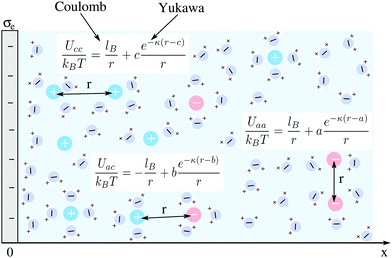 |
| | Fig. 1 Schematic illustration of a planar surface with surface charge density σe in contact with an aqueous solution containing monovalent ions of bulk cation and anion concentrations n0 and dielectric constant εW ≈ 80. Mobile ions interact with each other through their excluded volume, through a Coulomb potential, and through a Yukawa potential. The latter two account for electrostatic and hydration-mediated interactions, respectively. They are specified by the relationships Uaa(r), Uac(r), and Ucc(r) for anion–anion, anion–cation, and cation–cation interactions, respectively, where r is the ion-to-ion distance; see the text for details. The strength of the electrostatic interaction equals kBT if two ions are separated by a distance lB. Similarly, the strength of the hydration interaction equals kBT for an anion–anion pair at distance a, for an anion–cation pair at distance b, and for a cation–cation pair at distance c away from each other. | |
2.1 Mean-field theory
Our model starts with the total free energy,| | | Ftot = Uel + Uhyd + Fmix, | (1) |
that accounts for electrostatic interactions (Uel), for hydration interactions (Uhyd) and for an ideal or non-ideal mixing entropy contribution (Fmix) of the ions in solution. We discuss each term individually.
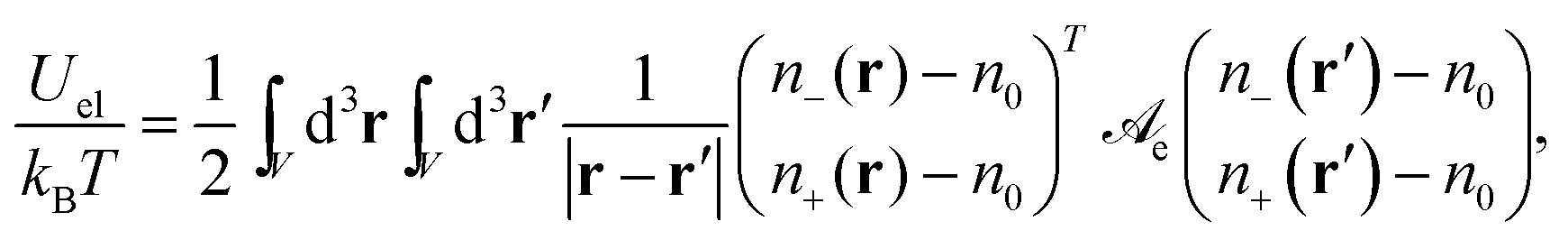
The electrostatic energy (in units of kBT) of the electrolyte can be expressed as
| | 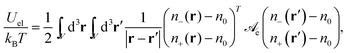 | (2) |
where
n−(
r) and
n+(
r) are the local concentrations of anions and cations, respectively, as function of the position vector
r. The two integrations are carried out over the volume
V that contains the ions. The electrostatic interaction matrix in
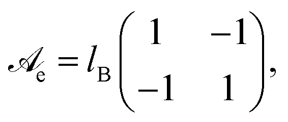
eqn (2),
| |  | (3) |
specifies the prefactors for the 1/
r-Coulomb potential between two cations and two anions (the diagonal elements), and between an anion and a cation (the non-diagonal elements). Recall that both ions are monovalent. The Bjerrum length is
lB = 0.7 nm for an aqueous medium (
εW ≈ 80) at room temperature. From
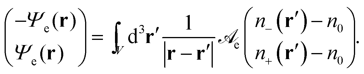
eqn (2) we define a dimensionless electrostatic potential
Ψe through
| |  | (4) |
The reason why only one single electrostatic potential appears in
eqn (4) is the vanishing determinant of
![[scr A, script letter A]](https://www.rsc.org/images/entities/char_e520.gif) e
e. We note the relation
Ψe =
eΦ/
kBT between the dimensionless electrostatic potential
Ψe and the electrostatic potential
Φ. As is well known, applying the Laplace operator ∇
2 to
eqn (4) and using Green's function
G(
r) = −1/(4π|
r|) yields the Poisson equation
| | | ∇2Ψe(r) = −4πlB[n+(r) − n−(r)]. | (5) |
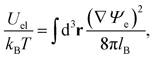
When expressed in terms of the dimensionless electrostatic potential, the electrostatic interaction energy reduces to the familiar expression
| | 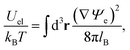 | (6) |
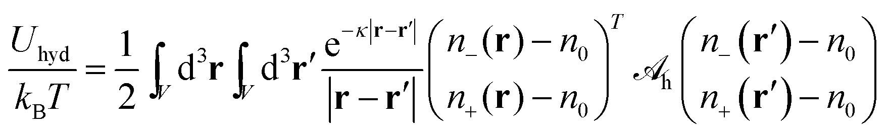
where the integration runs over all space. The energy due to Yukawa-like interaction potentials can be expressed in analogy to
eqn (2) by
| | 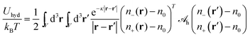 | (7) |
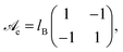
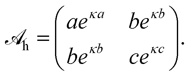
with a hydration interaction matrix
| | 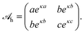 | (8) |
Recall that the constants
a,
b, and
c represent the distances where the interaction between an anion–anion, anion–cation, and cation–cation pair, respectively, equals
kBT. The values for
a,
b, and
c contribute to the specificity of the ion–ion interaction. In our present work we do not attempt to determine these parameters. Instead, we simply assume
a =
b =
c, thus leaving the analysis of asymmetric interactions and the identification with specific ions to be worked out in future studies. We also note that the parameter 1/
κ = 0.3 nm accounts for the characteristic decay length of ordered water layers.
1 Based on
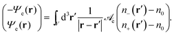
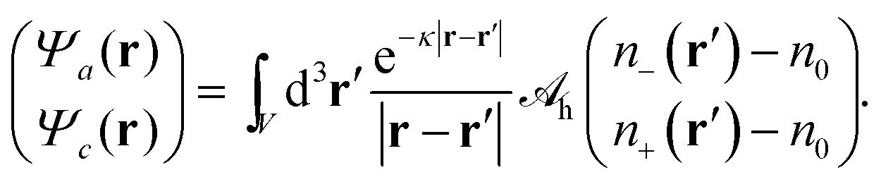
eqn (7), we define two non-electrostatic (hydration) potentials
Ψa and
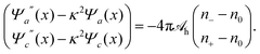
Ψcvia| |  | (9) |
Generally, there are indeed two independent hydration potentials because the determinant of the hydration interaction matrix, det(
h), may be non-vanishing. Special cases with det(
h) = 0 have been introduced and discussed in previous works. Specifically, Bohinc
et al.52 have used
h =
lne
κln{{(1 −
α)
2, −(1 −
α2)}, {−(1 −
α2), (1 +
α)
2}} with fixed constants
ln and
α. Brown
et al.55 have used
h =
lhe
κln{{0,0}, {0,1}} with a single fixed constant
lh. As already exercised for the electrostatic interaction, see the transition from
eqn (4) to (5), we can find an operator that produces a Yukawa-like Green's function. The operator is ∇
2 −
κ2 and the corresponding Green's function
G(
r) = −e
−κ|r|/(4π|
r|). With that we can cast
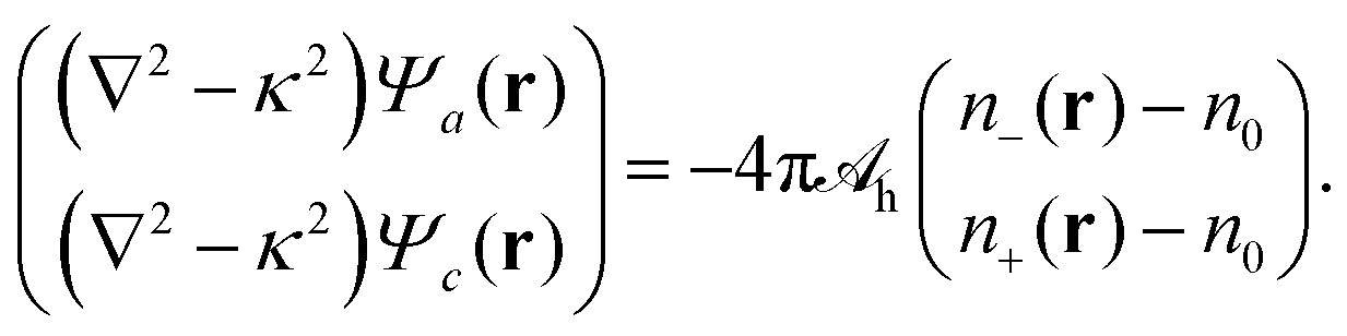
eqn (9) into the local form
| | 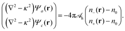 | (10) |
We refer to
eqn (10) as Helmholtz equations (with complex wavenumber and a source term). When expressed in terms of the potentials
Ψa and
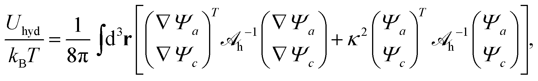
Ψc, the energy associated with hydration-mediated interactions becomes
| | 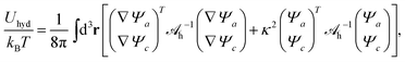 | (11) |
where the integration runs over all space and where
h−1 is the inverse of
h.
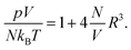
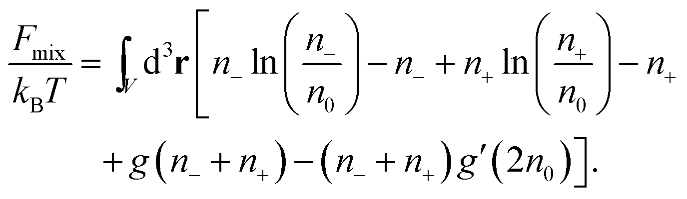
Consider finally the mixing entropy contribution Fmix in eqn (1). We express Fmix as the sum of an ideal mixing contribution of the mobile anions and cations and a non-ideal contribution that depends only on the total concentration n− + n+ but is otherwise general
| | 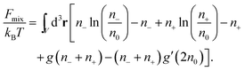 | (12) |
The function
g(
n) appears in the thermal equation of state
pV/(
NkBT) = 1 − (
V/
N)
g(
N/
V) +
g′(
N/
V) of a gas that exerts a pressure
p at fixed particle number
N, volume
V, and temperature
T. The choice
g(
n) = 0 leads to an ideal gas. Note that a prime denotes the first derivative; for example
g′(
n0) = [d
g(
n)/d
n]
n=n0. The function
g(
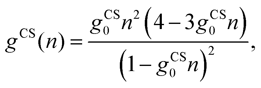
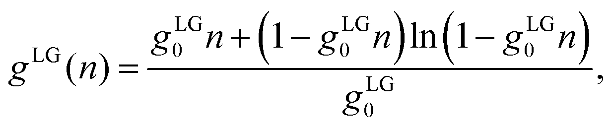
n) can be used to account for finite ion sizes. We consider two different choices,
g =
gCS(
n) and
g =
gLG(
n). The first one,
| | 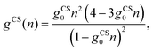 | (13) |
employs the Carnahan–Starling (CS) equation of state,
31,33,56 which treats all mobile ions as identical spherical particles of radius
R and corresponding volume
gCS0 = 4π
R3/3. The second one,
| | 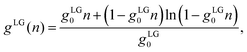 | (14) |
has been introduced by Bikerman and others;
21,26 it embodies a lattice gas model in which each cell occupies a volume
gLG0 = (2
R)
3 that hosts no more than one single ion of spatial extension 2
R.
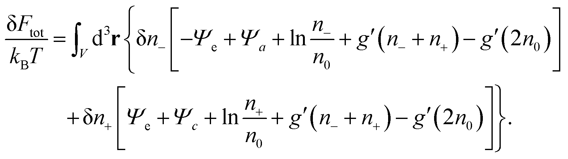
With all three contributions to the free energy in eqn (1) being specified (see eqn (6), (11) and (12)), we can carry out the first variation δFtot[Ψe(n−,n+), Ψa(n−,n+), Ψc(n−,n+), n−,n+], subject to the potentials Ψe, Ψa, Ψc being related to the ion concentrations through eqn (5) and (10). This results in
| |  | (15) |
Thermal equilibrium demands δ
Ftot = 0, which can only be fulfilled if each of the two expressions enclosed by square brackets in
eqn (15) vanishes identically,
| |  | (16) |
These two, generally transcendental, equations define the two relations
n− =
n−[
Ψe(
r),
Ψa(
r),
Ψc(
r)] and
n+ =
n+[
Ψe(
r),
Ψa(
r),
Ψc(
r)] which upon insertion into the Poisson and Helmholtz equations,
eqn (5) and (10), yield a system of three differential equations that define the mean-field potentials
Ψe(
r),
Ψa(
r), and
Ψc(
r).
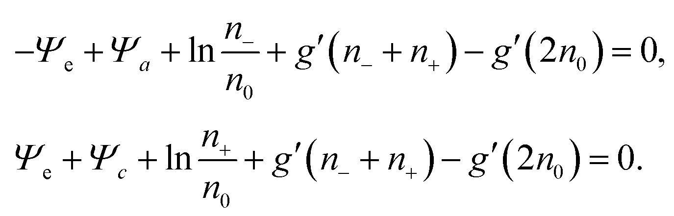
Previous models that include hydration-mediated interactions52,55 have focused on an ideal mixing free energy, Fmix, which results from setting g(n) = 0 in eqn (12). This implies the Boltzmann distributions n−(r) = n0eΨe(r)−Ψa(r) and n+(r) = n0e−Ψe(r)−Ψc(r). We refer to this specific case as the Poisson–Helmholtz–Boltzmann (PHB) approach.51 The corresponding PHB equations result from inserting the Boltzmann distributions into the Poisson and Helmholtz equations.
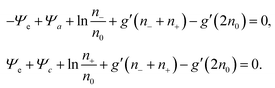
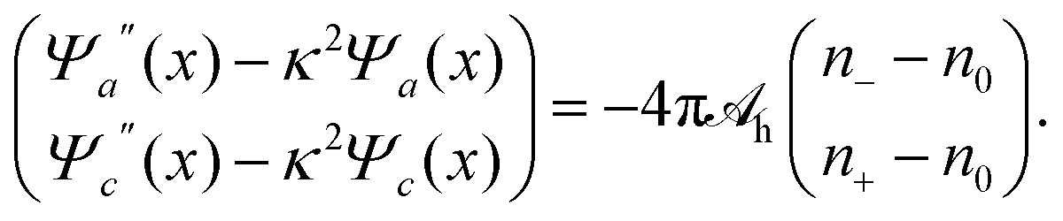
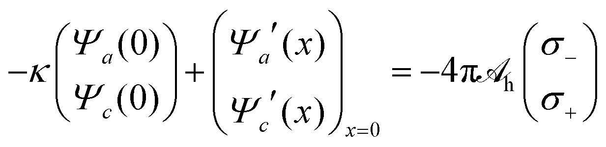
Because for our geometry (see Fig. 1) all system properties depend only on the x-coordinate, we replace the argument r by x. That is, Ψe/a/c(r) → Ψe/a/c(x), and n±(r) → n±(x). Eqn (16) then define the relations n− = n−[Ψe(x), Ψa(x), Ψc(x)] and n+ = n+[Ψe(x), Ψa(x), Ψc(x)] that enter the Poisson and Helmholtz equations
| Ψe′′(x) = −4πlB(n+ − n−), |
| |  | (17) |
where a prime denotes the derivative with respect to
x. These three second-order differential equations must be solved subject to appropriate boundary conditions, which follow from applying the Poisson and Helmholtz equations to an infinitely small region in the vicinity of
x = 0. The boundary conditions for solving Poisson's equation are
Ψe′(
x)|
x→0 = −4π
lBσe/
e and
Ψe′(
x)|
x→∞ = 0, and those for solving the Helmholtz equations are
| |  | (18) |
and
Ψa′(
x)|
x→∞ =
Ψc′(
x)|
x→∞ = 0. The quantities
σ+ and
σ− represent the surface densities of the sources responsible for the hydration-mediated interaction with mobile cations and anions, respectively. In our present work we identify the sum
σ− +
σ+ with the density of ordered water molecules in immediate contact to the electrode. Because the hydration-mediated ion–surface interaction is of non-electrostatic origin, it may be viewed as one contribution (among others, such as dispersion forces) to specific ion adsorption. We note the presence of the first term on the left-hand side of
eqn (18). It originates in the absence of mobile ions for
x < 0, which implies the exponential functions
Ψa(
x) =
Ψa(0)
eκx and
Ψc(
x) =
Ψc(0)
eκx in this region.
Once the potentials Ψe(x), Ψa(x), and Ψc(x) are known, we can compute the relation between the surface charge density σe and the surface potential Φ(0) = kBTΨe(0)/e, and from that, the differential capacitance
| |  | (19) |
Recall that studying the influence of hydration-mediated interactions on
Cdiff is one of the main objectives of the present work. Below we discuss
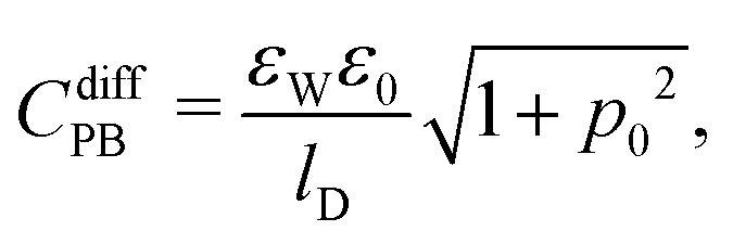
Cdiff based on seven different mean-field models that emerge as special cases from the formalism presented so far. Based on the identification P-Poisson, B-Boltzmann, H-Helmholtz, CS-Carnahan–Starling, and LG-lattice gas, we refer to these models as: classical PB, PB-Stern, PCS-Stern, PLG-Stern, PHB, PHCS, and PHLG. The first four models all ignore the presence of hydration-mediated interactions. The most simple case, the classical PB model, emerges upon assuming
g(
n) = 0 in
eqn (12). The ensuing differential capacitance is
| |  | (20) |
where we have introduced the definition
p0 = 2π
lBlDσe/
e. Here,
lD = (8π
lBn0)
−1/2 is the Debye screening length of the electrolyte. Adding a Stern layer (that is, a planar capacitor of capacitance
CStern =
εWε0/
dStern, where the Stern layer thickness
dStern =
R equals the ion radius
R) to the classical PB model produces a differential capacitance
CdiffPBCStern/(
CdiffPB +
CStern). We refer to this as the PB-Stern model. Adding a Stern layer to the Carnahan–Starling model (that is,
g(
n) =
gCS(
n) in
eqn (12)) yields a differential capacitance
CdiffCSCStern/(
CdiffCS +
CStern). We refer to this as the PCS-Stern model. Note that no closed-form expression for
CdiffCS is available. Adding a Stern layer to the lattice gas model (that is,
g(
n) =
gLG(
n) in
eqn (12)) yields a differential capacitance
CdiffLGCStern/(
CdiffLG +
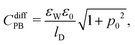
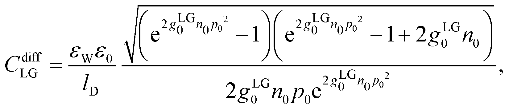
CStern). We refer to this as the PLG-Stern model. Here, a closed-form expression for the differential capacitance in the absence of a Stern layer is available,
19,26| | 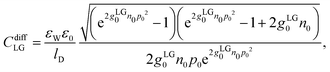 | (21) |
where we recall
gLG0 = (2
R)
3 and
p0 = 2π
lBlDσe/
e. The final three models all include the presence of hydration-mediated interactions but they differ in the expressions for
Fmix. Using
g(
n) = 0 (that is, ideal mixing for
Fmix) gives rise to the PHB model. Similarly, the choices
g(
n) =
gCS(
n) and
g(
n) =
gLG(
n) are referred to as the PHCS and PHLG models, respectively. Note that the inclusion of hydration-mediated interactions removes the need to explicitly add a Stern layer.
55
2.2 Monte Carlo simulations
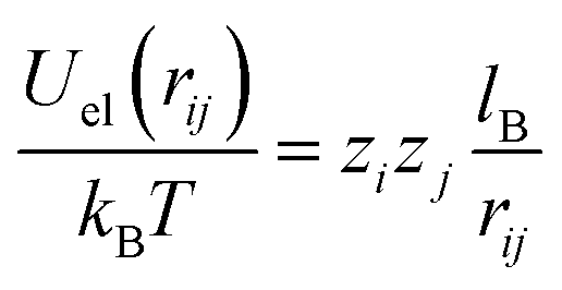
We have also carried out Metropolis Monte Carlo simulations in the canonical ensemble for a 1:1 electrolyte of bulk concentration n0 confined between two perfectly smooth and impenetrable walls placed at x = 0 and x = H. In order to describe the same system as in our mean-field approach, the surface located at x = 0 carries uniform surface densities of electric charges, σe, and of sources for the hydration-mediated interaction, σ+ and σ−. All simulations were performed in a rectangular simulation cell of dimensions H × L × L, with H = 30 nm and L = 10 nm. Periodic boundary conditions are applied in the L directions, and overall electroneutrality is ensured by the addition of neutralizing counterions. The electrolyte solution is modeled within the framework of the primitive model,59 where all ions are treated as charged hard spheres of radius R immersed in a medium of uniform dielectric constant εW. Hence, the electrostatic interaction energy between two distinct ions i and j is given by| | 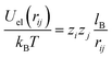 | (22) |
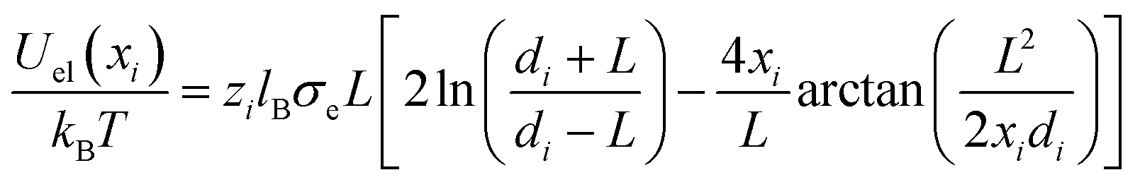
if rij ≥ 2R and Uel(rij) → ∞ otherwise. Here, zi and zj are the respective valencies and rij is the nearest-image distance between ions i and j. The electrostatic interaction energy of a given ion i at distance xi away from the charged surface is| | 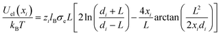 | (23) |
if xi ≥ R and Uel(xi) → ∞ for xi < R. In eqn (23) we have defined  .
.
Due to the long-range nature of the Coulomb potential, the total electrostatic energy of our system is not only given by the sum of Uel(rij) in eqn (22) over interactions of ions in the central cell with each other, but also with ions in the image cells. The same argument applies to the interaction of an ion with the fixed charges on the surface; see eqn (23). In order to include these contributions, we used the so-called External Potential Method (EPM) developed by Torrie and Valleau.35 According to this method, each ion in the central cell interacts with the image cells by means of the usual minimum image convention and with an external electrostatic potential given by the average ionic distributions in the image cells, including the charges located at the surface (we assume that the ionic distributions in the image cells are identical to those evaluated in the central cell).30,35,38,60
To incorporate hydration-mediated interactions into our simulations, we added the Yukawa-like interaction energies Uhyd(rij)/kBT = ae−κ(rij−a)/rij for an anion–anion pair, Uhyd(rij)/kBT = be−κ(rij−b)/rij for an anion–cation pair, and Uhyd(rij)/kBT = ce−κ(rij−c)/rij for a cation–cation pair. Similarly, for an anion interacting with the charged surface at distance xi away, we added the hydration-mediated interaction energy
| |  | (24) |
The expression for a cation that interacts with the surface is analogous,
Uhyd(
xi)/
kBT = 2π(
bσ−eκb +
cσ+eκc)
e−κxi/
κ. We point out that the total interaction potentials used in the Monte Carlo simulations between anion–anion, anion–cation, and cation–cation pairs are identical to the respective interactions
Uaa,
Uac, and
Ucc as introduced in
Fig. 1, supplemented by an additional excluded volume repulsion.
For each value of σe, our simulations yield the ionic distributions, n−(x) and n+(x). We used the corresponding charge density e[−n−(x) + n+(x)] to numerically solve the Poisson equation and thus to obtain the electrostatic potential Ψe(x). In order to compute the differential capacitance (Cdiff as defined in eqn (19)), we first created a set of discrete points representing the surface charge density, σe, and the corresponding electrostatic surface potential, Ψe(0) (see inset of Fig. 2). Then, the values of Cdiff are determined using the algorithm developed by Lamperski and Zydor.38 In Fig. 2, the results obtained from this algorithm and those predicted by obtaining the derivative simply through the slope of two neighboring data points (i.e., the two-point derivative) are shown as black bullets and blue-colored bar chart, respectively. We note that the Lamperski–Zydor algorithm is able to smoothen fluctuations resulting from the simulations and provides a reliable continuous derivative.
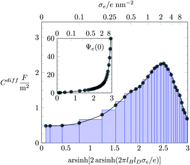 |
| | Fig. 2 Monte Carlo simulation results for the differential capacitance Cdiff = dσe/dΦ(0) as function of the surface charge density σe, obtained by two different methods: the Lamperski–Zydor algorithm (black bullets) and the two-point derivative (blue-colored bar-chart). The inset shows the variation of the dimensionless electrostatic surface potential, Ψe(0) = eΦ(0)/kBT, as function of σe. (Abscissa labels in the inset and main figure are identical.) The blue-colored bar-chart illustrates the intervals used for the two-point derivative. The displayed example is based on an ion radius of R = 0.2 nm and the absence of hydration interactions (a = b = c = 0). | |
2.3 Parameter selection
The present work focuses on hydration interactions that are symmetric. That is, the distance at which the hydration interaction strength equals kBT is the same for anion–anion, anion–cation, and anion–cation pairs, implying a = b = c in eqn (8). We also assume the ion–surface hydration interactions do not distinguish between anions and cations; this entails σ+ = σ−. The total source density σ− + σ+ = 5.0 nm−2 reflects the area density of water molecules that are bound to a flat surface.55 Throughout this work (with the exception of Fig. 8) we consider a 0.1 M salt concentration; this corresponds to a bulk concentration of n0 = 0.057 nm−3 or, equivalently, to a Debye screening length of lD = 1.0 nm. As already pointed out above, we fix the Bjerrum length lB = 0.7 nm and the characteristic decay length of the hydration potential κ−1 = 0.3 nm.
3 Results and discussion
In the following, we present and discuss Monte Carlo simulation and mean-field results for the differential capacitance Cdiff as function of the surface charge density σe, first in the absence and then in the presence of hydration interactions.
3.1 Absence of hydration interactions
We first investigate the joint presence of electrostatic and excluded volume interactions, yet in the absence of hydration interactions. Fig. 3 shows Cdiff as function of the surface charge density σe for a fixed ion radius R = 0.2 nm. Monte Carlo simulation results are displayed by bullets in Fig. 3. We observe a characteristic camel-like shape, the origin of which has been discussed intensively in the past.15–19 The initial growth of Cdiff(|σe|) as function of increasing magnitude of σe is captured by the classical PB model (see eqn (20)), which is shown by the dotted line in Fig. 3. Note that for σe = 0, eqn (20) predicts Cdiff = εWε0/lD = 0.71 F m−2. After passing through a maximum, Cdiff(|σe|) decreases roughly according to Cdiff ∼ 1/|σe|. The decrease results from packing of the counterions due to their finite size. We capture the 1/σe-dependence by a simple model in which the counterions are forced to adopt a uniform density 1/(2R)3, leading for a surface with charge density σe to a counterion layer thickness d = (2R)3σe/e. This implies a differential capacitance Cdiff = 2ε0εW/d = 2ε0εW/[(2R)3(σe/e)], which is shown in Fig. 3 by the gray solid lines in the large |σe|-region. The formation of counterion layers for large |σe| is also demonstrated in the inset of Fig. 3, which displays Monte Carlo simulation results of n−(x) for the three specific values: σe = 1.6 e nm−2 (blue curve), σe = 3.2 e nm−2 (green), and σe = 6.4 e nm−2 (red). A second layer of counterions in the latter case is visible at x = 3R = 0.6 nm.
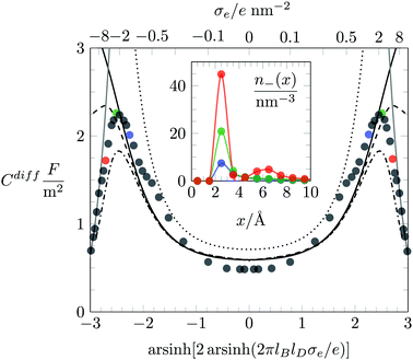 |
| | Fig. 3 Differential capacitance Cdiff as function of the surface charge density σe. Filled circles are results obtained by Monte Carlo simulations. The dotted, solid, dashed, and dash-dotted black lines correspond to the PB, PB-Stern, PCS-Stern, and PLG-Stern models, respectively. The thickness of the Stern layer, dStern = R, is equal to the ion radius R = 0.2 nm. The solid gray line is the result predicted by the approximation of dense ion packing, Cdiff = 2ε0εW/[(2R)3(σe/e)]. The inset shows Monte Carlo simulation results of the counterion concentration profiles n−(x) for various charge densities: σe = 6.4 e nm−2 (red), σe = 3.2 e nm−2 (green), and σe = 1.6 e nm−2 (blue). The same color scheme is used to mark the corresponding values of Cdiff in the main plot. | |
One striking feature of Fig. 3 is the inability of the classical PB model (dotted line, calculated according to eqn (20)) to reproduce the simulation results of Cdiff in the limit of small |σe|. Even upon the addition of a Stern layer of thickness dStern = R (the PB-Stern model – indicated by the solid line in Fig. 3), the discrepancy between simulation and theoretical model persists. Combining the Stern layer with a modified Poisson–Boltzmann model – namely the PCS-Stern model (the dashed line in Fig. 3) or the PLG-Stern model (the dash-dotted line in Fig. 3) – does produce a maximum in Cdiff for large |σe| but does not alter the prediction for Cdiff at small |σe|. The inability of the PB-Stern, PCS-Stern, and PLG-Stern models to reproduce Cdiff for small |σe| originates in the ad hoc assumption of adding a Stern layer whose thickness does not adjust as function of σe. We demonstrate below that our approach of incorporating hydration-mediated interactions in a consistent manner into the ion–ion interaction potential removes the need to invoke a Stern layer and leads to excellent agreement of mean-field predictions with the Monte Carlo simulation results. In particular, unlike for the exclusive presence of Coulomb and excluded volume interactions, where density functional theory is an established method to predict the differential capacitance,57,61 the additional presence of a soft hydration potential empowers mean-field models to successfully capture the behavior of Cdiff.
While Fig. 3 applies to a fixed ion radius of R = 0.2 nm, in Fig. 4 we show Cdiff(σe) for the three different choices R = 0.2 nm (black triangles), R = 0.4 nm (red diamonds), and R = 0.6 nm (green bullets), in each case together with a color-matching solid and dashed line that correspond to the PCS-Stern and PLG-Stern approaches, respectively. We first note that our simulations predict the maximum of Cdiff(|σe|) to move from a nonvanishing value of σe at low volume density of the ions (small R) to σe = 0 for high volume density (large R). This transition from a “camel”-shape to a “bell”-shape62 is consistent with predictions from theoretical modeling such as density functional theory,62,63 modified Grahame equations,19 and Monte Carlo simulations performed by Lamperski and coworkers.57,61,64,65
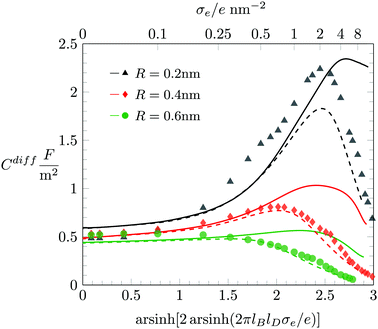 |
| | Fig. 4 Differential capacitance Cdiff as function of the surface charge density σe for various ion radii R when only electrostatics and finite ion size effects (but no hydration-mediated interaction, a = b = c = 0) are taken into account. Symbols mark results obtained from Monte Carlo simulations. Solid and dashed lines correspond to the PCS-Stern and PLG-Stern models, respectively. The Stern layer thickness is dStern = R. Different colors correspond to R = 0.2 nm (black), R = 0.4 nm (red), and R = 0.6 nm (green). | |
For |σe| ≪ 1 the two mean-field predictions coincide, and they are identical to the PB-Stern model. Due to the varying thickness dStern = R of the Stern layer, the differential capacitance of the PB-Stern model varies with R according to Cdiff = εWε0/(R + lD) for σe = 0. However, our simulation results suggest Cdiff(σe = 0) = 0.5 F m−2, virtually independent of R. Here again, as in Fig. 2, the Stern layer approach is not capable of reproducing the simulation results in the limit of small |σe|. To rationalize for why Cdiff(σe = 0) = 0.5 F m−2 remains independent of R we refer to our discussion in Fig. 7 below. From there it will become apparent that the predicted decrease of Cdiff for growing R according to the Stern model is counteracted (and effectively compensated) by a compression of the EDL due to a larger osmotic pressure exerted by the larger ions. Only when hydration interactions are accounted for does mean-field modelling appear to capture this mechanism.
In the other limit, that of large |σe|, we observe smaller Cdiff for larger ion radius R. In addition, while the PCS-Stern model qualitatively but not quantitatively agrees with the predictions of our simulations, the PLG-Stern model exhibits remarkably good agreement, and even better so with growing ion radius R.
3.2 Presence of hydration interactions
In the following, we discuss the influence of including hydration-mediated interactions on the differential capacitance Cdiff. Recall that we model hydration interactions as a soft, Yukawa-like, pair potential that is added to the Coulomb potential between any two mobile ions and between mobile ions and the surface. Fig. 5 displays Cdiff as function of σe for fixed R = 0.2 nm. The three differently colored sets of data points represent predictions from Monte Carlo simulations: a = b = c = 0.2 nm (black bullets), a = b = c = 0.4 nm (red diamonds), and a = b = c = 0.6 nm (green triangles). Clearly, growing hydration repulsion leads to larger ion–surface and ion–ion distances; this decreases Cdiff irrespective of σe. In the limit of large |σe|, all simulation results approach the limiting behavior Cdiff ≈ 2ε0εW/[(2R)3(σe/e)] (marked by the gray curve in Fig. 5), where hydration interactions become irrelevant because ions are densely packed. Note that the soft nature of the hydration interactions shifts the maximum of Cdiff(σe) to larger |σe|.
 |
| | Fig. 5 Differential capacitance Cdiff as function of the surface charge density σe for R = 0.2 nm and different values of a = b = c = 0.2 nm (black bullets), a = b = c = 0.4 nm (red diamonds), and a = b = c = 0.6 nm (green triangles). Monte Carlo simulation results are marked by the different symbols as indicated. The color-matching solid, and dash-dotted lines correspond to the PHB and PHLG models, respectively. For R = 0.2 nm we have also added a dashed line (in black), which displays the prediction of the PHCS model. The solid gray line marks the limiting behavior Cdiff = 2ε0εW/[(2R)3(σe/e)]. | |
Fig. 5 also shows results derived from the PHB (color-matching solid lines), PHCS (dashed lines) and PHLG models (dash-dotted lines). For |σe| ≪ 1, the different mean-field models (PHB, PHCS, and PHLG) coincide with each other and agree well with the Monte Carlo simulation results. We emphasize that no Stern layer is added. Instead, an ion depletion zone emerges naturally from the hydration-mediated repulsion between the ions and the surface.55 The effective thickness of the ion depletion zone adjusts so as to minimize the total free energy. As a result, the PHB model reproduces the trends of the simulation results for |σe| ≪ 1 quite accurately. For large |σe|, ion–ion correlations and ion packing effects become important. They can be described approximately by the PHLG model (the dash-dotted lines in Fig. 5), which predicts the function Cdiff(|σe|) to pass through a maximum. With growing a = b = c the maximum shifts to larger surface charge density |σe|. In other words, for stronger hydration-mediated interactions, Cdiff continues to grow up to higher |σe|. This indicates that the soft, hydration-mediated interactions render the diffuse counterion cloud more compressible, thus allowing its effective thickness to decrease as function of |σe|. However, for sufficiently large σe, Cdiff becomes independent of our choices for a = b = c, thus evidencing the saturation of counterion packing near the surface. Fig. 5 also shows the prediction of the PHB model (solid lines) and for R = 0.2 nm the prediction of the PHCS model (black dashed line).
In Fig. 6 we study how changing the ion radius R affects Cdiff at fixed a = b = c = 0.6 nm. Here again, Monte Carlo simulation results are marked by symbols as indicated in the figure legend. The color-matching solid and dashed lines display Cdiff according to the PHCS and PHLG models, respectively. It is notable that in the limit of small |σe| our Monte Carlo simulations predict Cdiff to increase with growing ion radius R. Based on the simple Stern layer model, one would expect Cdiff ∼ 1/R, which is in contrast to what is observed in the simulations. The PHLG model (dashed lines) predicts virtually no dependence of Cdiff on R for small |σe|, again in contrast to the simulation results. However, the PHCS model correctly captures the increase of Cdiff as function of R.
 |
| | Fig. 6 Differential capacitance Cdiff as function of the surface charge density σe when hydration-mediated interactions are present with a = b = c = 0.6 nm. Different colors correspond to different ion size R according to R → 0 nm (blue), R = 0.2 nm (black), R = 0.4 nm (red), R = 0.6 nm (green), and R = 0.8 nm (orange). Monte Carlo simulation results are marked by the different symbols as indicated. The color-matching solid, and dashed lines correspond to the PHCS and PHLG models, respectively. | |
The mechanism that explains why Cdiff increases with R for small |σe| originates in the increasing osmotic pressure of the ions in the bulk. The larger bulk pressure due to larger ion radius R tends to compactify the EDL and thus increases Cdiff. This assertion is supported by the upper diagram of Fig. 7, which shows the local anion concentration distribution n−(x) for fixed σe = 0. The black symbols correspond to R = 0.2 nm with a = b = c = 0 (filled circles) and a = b = c = 0.6 nm (open circles). The green symbols correspond to R = 0.6 nm with a = b = c = 0 (filled circles) and a = b = c = 0.6 nm (open circles). Note that anion and cation profiles are identical for σe = 0; no excess charge is present in this case at any point in the electrolyte. Clearly, the larger ions tend to accumulate more near the surface. In the absence of hydration-mediated interactions, the enhanced concentration of the larger ions compensates with the larger distance of the ion center to the surface so that Cdiff remains virtually unchanged (see Fig. 4). In the presence of soft, hydration-mediated interactions, the increase of the concentration n−(x) near the surface for larger R causes Cdiff to increase.
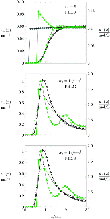 |
| | Fig. 7 Counterion concentration profile n−(x) near the charged planar surface, located at x = 0, for σe = 0 (upper diagram) and σe = 1.0 e nm−2 (middle and lower diagrams). Black and green circles/curves refer to R = 0.2 nm and R = 0.6 nm, respectively. Monte Carlo simulation data are indicated by filled circles for a = b = c = 0 and by open circles for a = b = c = 0.6 nm. Note that the Monte Carlo simulation results in the middle and lower diagrams are identical. In the upper and lower diagrams, dashed lines refer to the PHCS model. In the middle diagram, dash-dotted lines correspond to the PHLG model. Dotted horizontal lines at n = n0 = 0.057 nm−3 in the upper diagram correspond to the PB-Stern model. | |
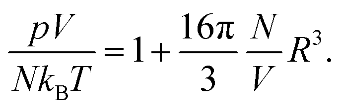
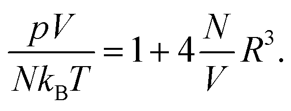
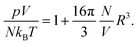
We address the question why for small and fixed |σe| the PHCS model, but not the PHLG model, captures the increase of Cdiff as function of R. The PHCS model is based on the Carnahan–Starling equation of state for a bulk fluid of spherical particles of radius R; it describes the bulk osmotic pressure of the finite-sized ions quite accurately. This is in contrast to the more restrictive PHLG model, which confines the number of states by introducing a lattice model where each cell can host exactly one or no particle. This results in a larger osmotic pressure of the particles in the PHCS model as compared to the PHLG model. More specifically, expanding the Carnahan–Starling equation of state31–33pV/(NkBT) = (1 + η + η2 − η3)/(1 − η)3, with η = (4/3)πR3N/V, in powers of the particle density N/V up to second order yields
| |  | (25) |
The same expansion for the lattice gas equation of state
pV/
kBT = −(
V/
v)ln(1 −
Nv/
V), with
v = (2
R)
3, leads to
| |  | (26) |
Hence the osmotic pressure exerted by the ions in the bulk is greater by roughly a factor of 4 when the PHCS model is compared to the PHLG model. This provides a rationale for the PHCS model being preferable over the PHLG model when predicting
Cdiff in the limit of small surface charge density |
σe|. Indeed, the black (in the limit
R → 0) and green (for
R = 0.6 nm) dashed lines in the upper diagram of
Fig. 7, which both refer to the PHCS model, differ only slightly, but they qualitatively follow the trends of the Monte Carlo simulations (larger counterion concentration close to the surface for larger ion radius
R).
We also discuss the behavior of Cdiff(σe) in Fig. 6 for large |σe|. In the limit R → 0 both the Monte Carlo simulations (filled blue squares) and the PHB model (blue solid line) predict Cdiff(|σe|) to monotonically increase. This is reminiscent of the classical PB model (see eqn (20)). Indeed, as σe grows to large positive values, the anion-to-anion distances in the EDL decrease until they are small compared to 1/κ, turning the Yukawa into a Coulomb interaction. The total anion–anion pair interaction is then lB/r + a/r, which implies similarity of the simulation data and the PHB prediction to the classical PB model, yet with a rescaled Bjerrum length lB → lB + a for large σe. As R grows, the simulation data predict Cdiff(|σe|) to pass through a maximum, which is captured better by the PHLG model than by the PHCS model. For R = 0.8 nm (the orange star symbol in Fig. 6), Cdiff(|σe|) decreases monotonously, which the PHLG model, but not the PHCS model, is able to reproduce. To understand the reason, we display in the middle and lower diagrams in Fig. 7 the local anion distribution n−(x) as predicted by Monte Carlo simulations (with R = 0.2 nm for the open black circles and R = 0.6 nm for the open green circles) and according to the PHLG model (dash-dotted lines in the middle diagram) and PHCS model (dashed lines in the lower diagram). The black and green colors refer to R = 0.2 nm and R = 0.6 nm, respectively. In addition, all data in the middle and lower diagrams of Fig. 7 refer to a = b = c = 0.6 nm and to σe = 1.0 e nm−2. Regarding the Monte Carlo simulation data, we observe that the larger counterions are more condensed onto the surface and form a second layer near x = 2 nm. The more pronounced condensation of the larger counterions results from the larger osmotic pressure of the ions in the bulk. Because at high ion concentrations in the EDL, ion–ion correlations become important, mean-field theory cannot be expected to even qualitatively capture the structural details of the counterion distribution n−(x). This is indeed not the case in Fig. 7, neither for the PHLG (middle diagram) nor the PHCS (lower diagram) model. However, the broader and more smeared out distribution for n−(x) predicted by the PHLG model appears to better account for the formation of a second (and other subsequent) ionic layers, thus placing the prediction for Cdiff closer to the Monte Carlo simulation data than the PHCS model is able to accomplish.
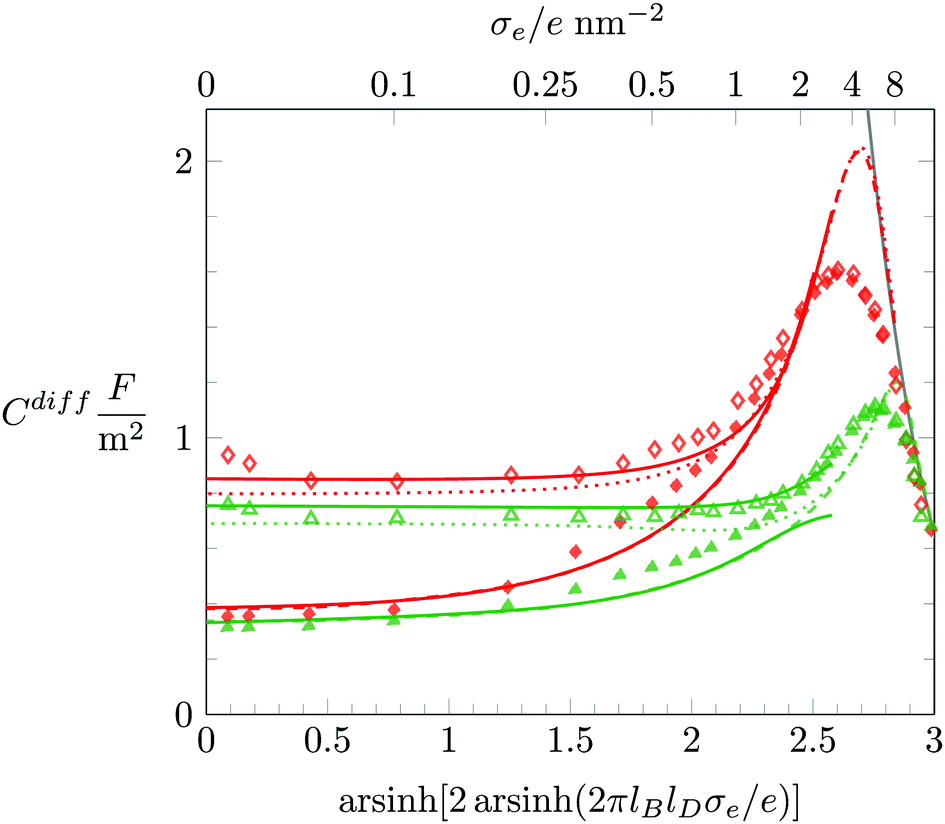
We conclude with a brief discussion about how Cdiff depends on the salt concentration n0. So far, all our results were derived for n0 = 0.1 M. In Fig. 8 we redisplay Monte Carlo simulation results for n0 = 0.1 M (filled symbols) and compare them with results for n0 = 1 M (open symbols), where the red and green coloring corresponds to a = b = c = 0.4 nm and a = b = c = 0.6 nm, respectively. We first recall that for highly charged surfaces counterions aggregate into a dense condensate, implying Cdiff ∼ σe−1. This limiting behavior is (again, as already in Fig. 3 and 5) shown as a solid gray line. The dense ion packing is independent of both the salt concentration and the degree of hydration repulsion. Hence, all simulation data for Cdiff fall onto a single curve at high σe. The PHLG model, which is shown as color-matching (red or green) dashed (for n0 = 0.1 M) and dotted (for n0 = 1 M) lines, captures this behavior, yet fails to quantitatively predict the maximum of Cdiff. For small σe the differential capacitance Cdiff grows with the salt content. As we have already observed in Fig. 6, the predictions of the PHCS model (the solid lines in Fig. 8) agree more closely with the simulation data than the predictions of the PHLG model. We note that for n0 = 0.1 M both simulation and mean-field description predict the minimum of Cdiff at σe = 0. In contrast, for n0 = 1 M the PHCS model predicts a (very shallow) minimum of Cdiff at around σe/e = 0.1 nm−2, which qualitatively agrees with the simulation data. The corresponding minimum for the PHLG model remains located at σe = 0. So, here again, the PHCS and PHLG models become the more favorable mean-field description in the low and high σe-regime, respectively.
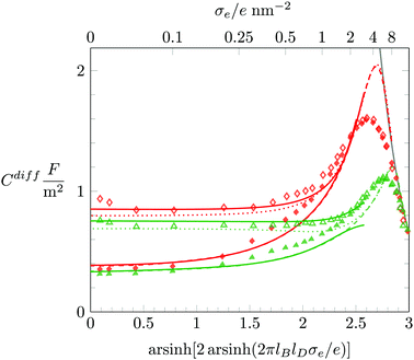 |
| | Fig. 8 Differential capacitance Cdiff as function of the surface charge density σe. Red and green coloring corresponds to a = b = c = 0.4 nm and a = b = c = 0.6 nm. Open and filled symbols correspond to predictions of Monte Carlo simulations for 1 M and 0.1 M bulk salt content, respectively. The solid lines refer to the PHCS model. The dashed (for n0 = 0.1 M) and dotted (for n0 = 1 M) lines refer to the PHLG model. The ion radius is R = 0.2 nm. The solid gray line marks the limiting behavior Cdiff = 2ε0εW/[(2R)3(σe/e)]. | |
4 Conclusion
In this work we have expanded our theoretical approach of incorporating hydration-mediated interactions into the mean-field Poisson–Boltzmann formalism. We have not only incorporated distinct hydration-mediated interactions for each pair of interacting ions, i.e., anion–anion, anion–cation and cation–cation, but we have also taken into account the finite size of the ions by using two different mean-field approaches based on the Carnahan–Starling equation of state and the lattice gas model.
We have studied the influence of hydration-mediated interactions on the differential capacitance using Monte Carlo simulations and compared them with our mean-field models. When hydration interactions are accounted for, a thin charge-depleted region that separates the surface from the diffuse part of the EDL emerges naturally.55 The electric potential in this thin region drops linearly, as it does in a Stern layer. However, unlike the thickness of the classical Stern layer, the charge-depleted zone is able to adjust its spatial extension. As a result we find good agreement of our simulation results with the mean-field predictions, for small surface charge density if a non-ideal mixing entropy according to the Carnahan–Starling equation is employed and for large surface charge density on the basis of the lattice gas approach.
Thus far, we have applied our mean-field model to symmetric hydration-mediated interactions, where all ion pairs exhibit the same interactions irrespective of their chemical nature. We plan to also investigate asymmetric systems with three independent interaction parameters, a, b, and c. Note that, so far, no dielectric saturation effects are taken into account in our model; the assumption of a uniform dielectric background is, in fact, what enabled us to perform Monte Carlo simulations conveniently. Dielectric saturation effects further decrease the differential capacitance.57 In the most simple case, for the PB-Stern model, the differential capacitance CdiffPBCStern/(CdiffPB + CStern) with CStern = εSternε0/dStern obviously decreases if the dielectric constant εStern inside the Stern layer is reduced. In the future, the combined effects of hydration-mediated ion–ion interactions and concomitant changes in the local (or non-local) dielectric constant should also be addressed.
Acknowledgements
All simulations were performed by resources supplied by the Center of Scientific Computing (NCC/GridUNESP) of the Sao Paulo State University (UNESP). Daniel L. Z. Caetano acknowledges the Sao Paulo Research Foundation (FAPESP, Process Grant No. 2015/03549-9) for the financial support. Guilherme V. Bossa acknowledges a doctoral scholarship from CAPES Foundation/Brazil Ministry of Education (Grant No. 9466/13-4). Vinicius M. de Oliveira was supported by the Conselho Nacional de Desenvolvimento Científico e Tecnológico (CNPq, Process Grant No. 141985/2013-5). Matthew A. Brown acknowledges the Swiss National Science Foundation for an International Short Visit travel grant (Grant No. 162320).
References
- J. N. Israelachvili and P. M. McGuiggan, Science, 1988, 241, 795–800 CAS.
-
A. G. Volkov, Liquid interfaces in chemical, biological and pharmaceutical applications, CRC Press, 2001 Search PubMed.
-
R. J. Hunter, Foundations of colloid science, Oxford University Press, 2001 Search PubMed.
- B. Hou, W. Bu, G. Luo, P. Vanysek and M. L. Schlossman, J. Electrochem. Soc., 2015, 162, H890–H897 CrossRef CAS.
- H. Ohshima, Sci. Technol. Adv. Mater., 2016, 1–13 Search PubMed.
- R. Parsons, Chem. Rev., 1990, 90, 813–826 CrossRef CAS.
- D. Brogioli, R. Zhao and P. Biesheuvel, Energy Environ. Sci., 2011, 4, 772–777 CAS.
- A. Härtel, M. Janssen, S. Samin and R. van Roij, J. Phys.: Condens. Matter, 2015, 27, 194129 CrossRef PubMed.
- F. Mugele, B. Bera, A. Cavalli, I. Siretanu, A. Maestro, M. Duits, M. Cohen-Stuart, D. van den Ende, I. Stocker and I. Collins, Sci. Rep., 2015, 5, 10519 CrossRef PubMed.
-
B. E. Conway, Electrochemical supercapacitors: scientific fundamentals and technological applications, Springer Science & Business Media, 2013 Search PubMed.
- C. Largeot, C. Portet, J. Chmiola, P.-L. Taberna, Y. Gogotsi and P. Simon, J. Am. Chem. Soc., 2008, 130, 2730–2731 CrossRef CAS PubMed.
- P. Attard, Adv. Chem. Phys., 1996, 92, 1–160 CrossRef CAS.
- G. Gouy, J. Phys., 1910, 9, 457–467 Search PubMed.
- D. L. Chapman, Philos. Mag. (1798–1977), 1913, 25, 475–481 CrossRef.
- G. Valette, J. Electroanal. Chem. Interfacial Electrochem., 1981, 122, 285–297 CrossRef CAS.
- A. A. Kornyshev, J. Phys. Chem. B, 2007, 111, 5545–5557 CrossRef CAS PubMed.
- G. Valette, J. Electroanal. Chem. Interfacial Electrochem., 1982, 138, 37–54 CrossRef CAS.
- M. Z. Bazant, M. S. Kilic, B. D. Storey and A. Ajdari, Adv. Colloid Interface Sci., 2009, 152, 48–88 CrossRef CAS PubMed.
- Y. Nakayama and D. Andelman, J. Chem. Phys., 2015, 142, 044706 CrossRef PubMed.
- O. Stern, Z. Elektrochem., 1924, 30, 1014–1020 Search PubMed.
- J. Bikerman, Philos. Mag. (1798–1977), 1942, 33, 384–397 CrossRef CAS.
- C. W. Outhwaite and L. B. Bhuiyan, J. Chem. Soc., Faraday Trans. 2, 1983, 79, 707–718 RSC.
- S. Lamperski and C. Outhwaite, Langmuir, 2002, 18, 3423–3424 CrossRef CAS.
- M. S. Kilic, M. Z. Bazant and A. Ajdari, Phys. Rev. E: Stat., Nonlinear, Soft Matter Phys., 2007, 75, 021502 CrossRef PubMed.
- V. Kralj-Iglič and A. Iglič, J. Phys. II, 1996, 6, 477–491 CrossRef.
- I. Borukhov, D. Andelman and H. Orland, Phys. Rev. Lett., 1997, 79, 435–438 CrossRef CAS.
- K. Bohinc, V. Kralj-Iglič and A. Iglič, Electrochim. Acta, 2001, 46, 3033–3040 CrossRef CAS.
- D. Henderson, L. Blum and W. R. Smith, Chem. Phys. Lett., 1979, 63, 381–383 CrossRef CAS.
- S. L. Carnie, D. Y. Chan, D. J. Mitchell and B. W. Ninham, J. Chem. Phys., 1981, 74, 1472–1478 CrossRef CAS.
- A. Martn-Molina, M. Quesada-Pérez and R. Hidalgo-Álvarez, J. Phys. Chem. B, 2006, 110, 1326–1331 CrossRef PubMed.
- T. Boublk, J. Chem. Phys., 1970, 53, 471–472 CrossRef.
- G. Mansoori, N. Carnahan, K. Starling and T. Leland Jr, J. Chem. Phys., 1971, 54, 1523–1525 CrossRef CAS.
- L. Lue, N. Zoeller and D. Blankschtein, Langmuir, 1999, 15, 3726–3730 CrossRef CAS.
- D. Antypov, M. C. Barbosa and C. Holm, Phys. Rev. E: Stat., Nonlinear, Soft Matter Phys., 2005, 71, 061106 CrossRef PubMed.
- G. Torrie and J. Valleau, J. Chem. Phys., 1980, 73, 5807–5816 CrossRef CAS.
- M. Valisko, D. Henderson and D. Boda, J. Phys. Chem. B, 2004, 108, 16548–16555 CrossRef CAS.
- P. Zarzycki, J. Colloid Interface Sci., 2006, 297, 204–214 CrossRef CAS PubMed.
- S. Lamperski and A. Zydor, Electrochim. Acta, 2007, 52, 2429–2436 CrossRef CAS.
-
W. Kunz, Specific ion effects, World Scientific, 2010, vol. 325 Search PubMed.
- J. N. Israelachvili and H. Wennerstrom, J. Phys. Chem., 1992, 96, 520–531 CrossRef CAS.
- I. Kalcher and J. Dzubiella, J. Chem. Phys., 2009, 130, 134507 CrossRef PubMed.
- I. Kalcher, J. C. F. Schulz and J. Dzubiella, Phys. Rev. Lett., 2010, 104, 097802 CrossRef PubMed.
- J. I. Kilpatrick, S.-H. Loh and S. P. Jarvis, J. Am. Chem. Soc., 2013, 135, 2628–2634 CrossRef CAS PubMed.
- I. Siretanu, D. Ebeling, M. P. Andersson, S. S. Stipp, A. Philipse, M. C. Stuart, D. Van Den Ende and F. Mugele, Sci. Rep., 2014, 4, 4956 CAS.
- T. Baimpos, B. R. Shrestha, S. Raman and M. Valtiner, Langmuir, 2014, 30, 4322–4332 CrossRef CAS PubMed.
- P. Koelsch, P. Viswanath, H. Motschmann, V. L. Shapovalov, G. Brezesinski, H. Mohwald, D. Horinek, R. R. Netz, K. Giewekemeyer, T. S. Alditt, H. Schollmeyer, R. von Klitzing, J. Daillant and P. Guenoun, Colloids Surf., A, 2007, 303, 110–136 CrossRef CAS.
- D. Ben-Yaakov, D. Andelman, D. Harries and R. Podgornik, J. Phys.: Condens. Matter, 2009, 21, 424106 CrossRef PubMed.
- J. Stafiej, D. Di Caprio and J. Badiali, J. Chem. Phys., 1998, 109, 3607–3618 CrossRef CAS.
- Y. Burak and D. Andelman, Phys. Rev. E: Stat. Phys., Plasmas, Fluids, Relat. Interdiscip. Top., 2000, 62, 5296 CrossRef CAS.
- E. Ruckenstein and M. Manciu, Langmuir, 2002, 18, 7584–7593 CrossRef CAS.
- K. Bohinc, A. Shrestha and S. May,
Eur. Phys. J. E: Soft Matter Biol. Phys., 2011, 34, 1–10 Search PubMed.
- K. Bohinc, A. Shrestha, M. Brumen and S. May, Phys. Rev. E: Stat., Nonlinear, Soft Matter Phys., 2012, 85, 031130 CrossRef PubMed.
- J. Israelachvili and D. Sornette, J. Phys., 1985, 46, 2125–2136 Search PubMed.
- S. Marcelja and N. Radic, Chem. Phys. Lett., 1976, 42, 129–130 CrossRef CAS.
- M. A. Brown, G. V. Bossa and S. May, Langmuir, 2015, 31, 11477–11483 CrossRef CAS PubMed.
- N. F. Carnahan and K. E. Starling, J. Chem. Phys., 1969, 51, 635–636 CrossRef CAS.
- C. W. Outhwaite, S. Lamperski and L. B. Bhuiyan, Mol. Phys., 2011, 109, 21–26 CrossRef CAS.
- A. Mirzoev and A. P. Lyubartsev, Phys. Chem. Chem. Phys., 2011, 13, 5722–5727 RSC.
-
T. L. Hill, An introduction to statistical thermodynamics, Courier Corporation, 2012 Search PubMed.
- B. Jönsson, H. Wennerstroem and B. Halle, J. Phys. Chem., 1980, 84, 2179–2185 CrossRef.
- S. Lamperski and D. Henderson, Mol. Simul., 2011, 37, 264–268 CrossRef CAS.
- D. Jiang, D. Meng and J. Wu, Chem. Phys. Lett., 2011, 504, 153–158 CrossRef CAS.
- D. Henderson, S. Lamperski, Z. Jin and J. Wu, J. Phys. Chem. B, 2011, 115, 12911–12914 CrossRef CAS PubMed.
- S. Lamperski, C. W. Outhwaite and L. B. Bhuiyan, J. Phys. Chem. B, 2009, 113, 8925–8929 CrossRef CAS PubMed.
- S. Lamperski, M. Płuciennik and C. W. Outhwaite, Phys. Chem. Chem. Phys., 2015, 17, 928–932 RSC.
|
| This journal is © the Owner Societies 2016 |
Click here to see how this site uses Cookies. View our privacy policy here. 
 Open Access Article
 This Open Access Article is licensed under a Creative Commons Attribution-Non Commercial 3.0 Unported Licence
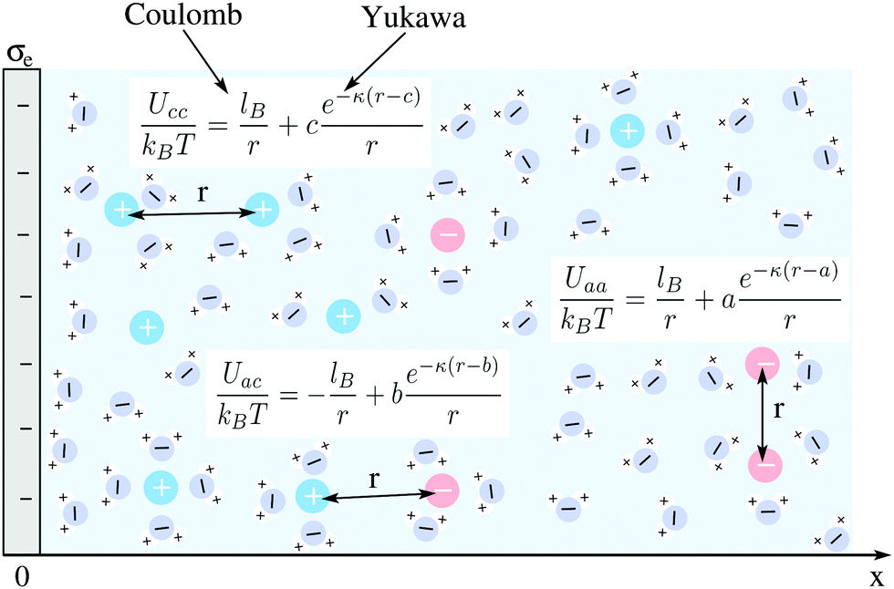
 .
.