 Open Access Article
Creative Commons Attribution 3.0 Unported Licence
Low-cost optical manipulation using hanging droplets of PDMS†
Craig
McDonald
* and
David
McGloin
SUPA, Division of Physics, University of Dundee, Nethergate, Dundee, Scotland. E-mail: cymcdonald@dundee.ac.uk
First published on 17th June 2015
Abstract
We propose and demonstrate a low-cost optical micromanipulation system that makes use of simple microfabricated components coupled to a smartphone camera for imaging. Layering hanging droplets of polydimethylsiloxane (PDMS) on microscope coverslips, and curing with a 100 W bulb, creates lenses capable of optical trapping. Optically trapped 3.93 μm silica beads were imaged with a second hanging droplet lens, doped with 1400 μg mL−1 Sudan II dye. Through doping, a lens with an integrated long-pass filter that effectively blocks the 532 nm trapping light was produced. Illumination was provided by shining a lamp into polystyrene foam packaging, perpendicular to the imaging path, producing a diffuse light source. We observed two dimensional trapping and report a Q value of ∼8.9 × 10⁻³. The techniques here are an addition to the growing body of work on low cost and adaptable microfluidics.
Introduction
Light microscopes have become ubiquitous in modern research laboratories. Through their combination with optical tweezers, high-end systems which provide insight into the physical, biological and chemical processes occurring in single molecules,1 aerosols2 and liquids3 have been created. However, these sophisticated systems come with an associated high cost, thus limiting their use both in research labs throughout the world (especially the developing world) but also in pedagogical settings.The development of elastomeric optics using polydimethylsiloxane (PDMS)4 has provided a high quality, low-cost, alternative to many optical components. PDMS has a high transparency (>95%) within the visible wavelength range and a high refractive index (n = 1.47–1.55), making it an ideal material to fashion lenses from. The low moulding temperature (<100 °C) of PDMS negates the need for specialised high temperature equipment, making it easy to work with in the lab.4 Elastomeric optics have found use in an increasing number of novel applications such as a rubber microscope,5 biologically inspired wide field lenses6 and a low-cost digital dermascope, which makes use of a mobile phone with added lenses fabricated from hanging droplets of PDMS.7
With the unprecedented growth of the mobile phone market, low-cost miniature microscopes that exploit the high quality digital camera of many mobile phones have been developed.8–11 Much recent work in the lab on a chip field makes use of smartphone sensing capabilities.12
Liquid droplets can be used to magnify small objects.13,14 A hanging droplet is formed when the interfacial energies (liquid, air and solid surface) and gravity reach equilibrium.14,15 By repeatedly adding and curing a hanging PDMS droplet, Lee et al. formed low-cost elastomer lenses which were able to resolve structures as small as 4 μm.7
In this paper, we present a low-cost and low-tech method of creating PDMS droplet lenses and use these droplet lenses as the basis of a basic optical trap. We use a second droplet lens, doped with Sudan II dye, and a commercial smartphone to image optically trapped 3.93 μm silica beads. Doping of PDMS with Sudan II dye, prior to moulding, produces a long pass filter with negligible autofluorescence.16 Integration of the imaging lens and long pass filter allowed for a more compact system, while still effectively blocking the 532 nm trapping light, preventing saturation of the phone camera. Illumination was provided by shining a lamp into polystyrene foam packaging, perpendicular to the imaging path, producing a diffuse light source that was sufficient for resolving the silica beads. At all stages of fabrication of the system we present methods which make use of materials that are often discarded or overlooked in the lab, or are easily attainable for a low cost. Neglecting the cost of a laser, which could be replaced by a laser pointer or other low cost alternative, our system can be constructed for approximately £23.23, a full cost breakdown of all components required is available in the ESI.† We also present measurements of the trapping ability and efficiency of a droplet lens based optical manipulation system.
Our work fits in very well with the burgeoning field of microfluidics for developing world, real world, applications17 and should integrate straightforwardly with existing optofluidic devices and urban sensing systems.
Materials and methods
Fabricating the trapping lens with a hanging droplet
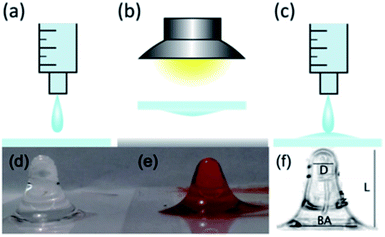
The trapping lens of our optical manipulation system was formed from hanging droplets of PDMS, which had been prepared using the typical soft lithography PDMS procedure, and followed similar steps as those outlined by Lee et al.,7 and shown in Fig. 1(a)–(c). That is to say, PDMS monomer and hardener were mixed at a ratio of 10![[thin space (1/6-em)]](https://www.rsc.org/images/entities/char_2009.gif) :
:![[thin space (1/6-em)]](https://www.rsc.org/images/entities/char_2009.gif) 1 v/v (Sylgard 184 Silicone Elastomer kit, Dow Corning, Coventry, UK) and then placed in a vacuum desiccator until all bubbles were removed. A 1 mL syringe (BD Plastipak, Ref: 300013) was carefully filled with PDMS and pressure applied until a single drop (<100 μL) fell from the syringe on to a microscope coverslip, thickness no. 1. The microscope slide was immediately inverted and suspended (∼20 mm) above a sheet of tin foil on the lab bench. Any excess PDMS falls from the slide until single drips are formed.
1 v/v (Sylgard 184 Silicone Elastomer kit, Dow Corning, Coventry, UK) and then placed in a vacuum desiccator until all bubbles were removed. A 1 mL syringe (BD Plastipak, Ref: 300013) was carefully filled with PDMS and pressure applied until a single drop (<100 μL) fell from the syringe on to a microscope coverslip, thickness no. 1. The microscope slide was immediately inverted and suspended (∼20 mm) above a sheet of tin foil on the lab bench. Any excess PDMS falls from the slide until single drips are formed.
An anglepoise lamp was used to lower a 100 W incandescent light bulb to ∼20 mm above the microscope slide, to provide heat for the curing step, while the tin foil reflected the heat back towards the droplet lens. Temperatures in excess of 100 °C could be reached, with temperature crudely controlled by raising and lowering the light bulb. Droplet lenses were left in the “oven” until set, which took up to 15 minutes, at temperatures ranging from 70–80 °C. In order to shorten the focal length and increase the numerical aperture (NA) of the lens, up to four droplets were layered one on top of each other, with each droplet cured before the next was applied. Due to the maximum surface tension that the droplet can hold before falling, the eventual droplet shape at the apex of the lens resembles that of a parabola, with a curvature that increases with layer number. The fabricated trapping lens is shown in Fig. 1(d) and cost approximately £0.06 per lens, including the microscope cover glass used as the support layer.‡
The length of the droplet lens (L) was found to vary, with typical measured values of 8.48 ± 0.19 mm and 7.38 ± 0.15 mm. However, the diameter of the entrance pupil (D) and back aperture (BA) was found to remain roughly constant, with average values of, respectively, 2.62 ± 0.27 mm and 6.1 ± 0.2 mm. This led to a variation in measured focal lengths of different lenses, with used trapping lenses having a focal length 0.9 ± 0.21 mm and 1.0 ± 0.26 mm. The effective NA of these lenses was estimated as 0.70 ± 0.17 and 0.68 ± 0.18.
Combined long-pass filter and imaging lens fabrication
To image the optically trapped beads with a droplet lens and a mobile phone camera, it was necessary to filter the trapping light in order to prevent saturation of the camera. This was achieved by doping the PDMS mixture with 1400 μg mL−1 Sudan II dye prior to moulding. 14 mg of Sudan II dye (Sigma-Aldrich, Gillingham, UK) was first dissolved in ∼1 mL of toluene and then added to premixed PDMS monomer and hardener, ratio of 10![[thin space (1/6-em)]](https://www.rsc.org/images/entities/char_2009.gif) :
:![[thin space (1/6-em)]](https://www.rsc.org/images/entities/char_2009.gif) 1 v/v, to give a dye-loading of 1400 μg mL−1.16 Manual mixing was continued until a uniform PDMS colour was observed. A hanging droplet lens was then fabricated, using the coloured PDMS, at an increased cost of £0.08 per lens, by following the steps outlined above, the result of which is shown in Fig. 1(e).
1 v/v, to give a dye-loading of 1400 μg mL−1.16 Manual mixing was continued until a uniform PDMS colour was observed. A hanging droplet lens was then fabricated, using the coloured PDMS, at an increased cost of £0.08 per lens, by following the steps outlined above, the result of which is shown in Fig. 1(e).
Illumination and optical manipulation setup assembly
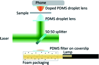
Our experimental set-up is shown in Fig. 2 and makes use of a 1.5 W (maximum output) 532 nm solid-state laser (Model: Ventus, Laser Quantum) as the trapping source. No expansion optics were used before the droplet lens in order to keep the system as simple as possible. A 50![[thin space (1/6-em)]](https://www.rsc.org/images/entities/char_2009.gif) :
:![[thin space (1/6-em)]](https://www.rsc.org/images/entities/char_2009.gif) 50 beam splitter (EBS1, Thorlabs, £23.08) was used to reflect the trapping light up to the clear PDMS droplet lens and transmit the white light illumination. Transmission microscopy, where the sample is illuminated from below and imaged from above, was chosen as it was necessary to place the mobile phone camera in direct contact with the imaging lens.
50 beam splitter (EBS1, Thorlabs, £23.08) was used to reflect the trapping light up to the clear PDMS droplet lens and transmit the white light illumination. Transmission microscopy, where the sample is illuminated from below and imaged from above, was chosen as it was necessary to place the mobile phone camera in direct contact with the imaging lens.
Illumination of the sample was achieved by shining a lamp into polystyrene foam packaging§ perpendicular to the imaging path, Fig. 2. This produced diffuse light, which was sufficient to illuminate the sample without saturating the camera. Images presented in this paper were achieved through illumination with a Thorlabs OSL1-EC fibre illuminator as it was convenient. We found that stray laser light was reflecting from the foam packaging and illuminating the sample with scattered laser light and reducing the image contrast. To counteract this effect we made a PDMS filter, consisting of a single droplet of doped PDMS on a microscope coverslip and cured in a non-inverted geometry. This droplet filter was placed in the illumination pathway, preventing the scatter from degrading the image quality.
Results and discussion
Optical manipulation using a drip lens
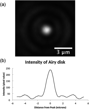
Initially, the focal spot produced by the drip lens was investigated to ensure a spot of sufficient quality to trap was produced. A Mitutoyo 0.55 NA 100× long working distance objective was used to image the focal spot on to a CCD camera. Fig. 3 shows the experimental airy disk obtained from a droplet lens, the focal length of which was measured as 0.9 ± 0.2 mm, giving an estimated effective NA of 0.70 ± 0.17. | ||
| Fig. 3 (a) Airy disk produced by PDMS droplet lens, imaged with Mitutoyo 0.55 NA 100× long working distance objective. (b) Line profile through centre of Airy disk. | ||
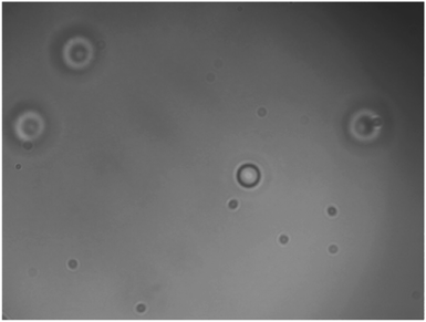
A suspension of 3.93 μm diameter silica beads in deionised water, between two microscope coverslips separated by a vinyl spacer, was used as the trapping sample. The particle size was chosen as previous studies7 have shown the smallest resolvable structure with droplet lenses to be 4 μm. Fig. 4 shows a 3.93 μm silica bead which has been trapped using a PDMS droplet lens. We found that the minimum power to trap these beads was 34.0 ± 0.4 mW, in the focal spot. Particle height was observed to change as a function of power, indicating two dimensional trapping.
 | ||
| Fig. 4 3.93 μm silica bead (in focus), optically trapped in two dimensions with a clear PDMS droplet lens, among untrapped, and therefore out of focus, beads. Imaged with Mitutoyo 0.55 NA 100× long working distance objective. A video of the trapped bead is available in the ESI.† | ||
In order to examine the ability of the droplet based trap to function as a more robust research grade instrument, a simple measure of the transverse Q value18 of the trapping spot was made. The simplest method to find the transverse Q value is to laterally displace the trapped sphere at increasing velocity until it falls from the trap, which is equivalent to the sphere remaining stationary while the surrounding fluid is moved. The applied drag force at the point of escape is equal to the trapping force of the optical manipulation system. Moving the sample with increasing velocity increases the drag force acting on the acting on the sphere, given by Stokes' law. Making use of the Stokes' drag technique, and the expression F = Q(nmP/c), where F and P are, respectively, the trapping force and power, nm is the suspending medium's refractive index and c being the speed of light, the trapping efficiency of the system was determined. 3.93 μm beads were trapped with 58.48 ± 0.08 mW of laser power and a Q value of 0.0089 ± 0.0001 was measured.
The low Q value indicates that quantitative measurements, or experiments which require high optical forces, would not be suited to our low cost, droplet lens based optical manipulation system. However, qualitative measurements and trial experiments could be easily performed.
Drip lens imaging
The Mitutoyo objective and CCD camera were removed and replaced with the doped PDMS droplet lens and the camera from a Samsung Galaxy S3 Mini smartphone.¶ At first, the trapping laser was turned off to ensure that the addition of Sudan II dye did not negatively impact the imaging ability of the lens. Using the macro photography autofocus and digital zoom features on the smartphone camera, the 3.93 μm beads were resolvable. When exploiting the camera's 4× digital zoom, each pixel was found to correspond to 0.22 ± 0.1 μm.The laser was turned on and power slowly increased, while the smartphone camera was monitored for any sign of laser light transmitted through the filter lens. Trap power was increased until optical trapping was observed, Fig. 5. Trap power was further increased to 112.2 ± 0.2 mW, more than 3 times the minimum trapping power required, in order to test the filtering ability of the doped droplet lens. At this power, the trapping light started to be visible through the doped PDMS droplet lens.
Conclusions
The optical manipulation system presented here can be fabricated with very little optical experience and at a very low cost. Although our system may not be suitable for high precision work, qualitative, low precision quantitative measurements and trial experiments could be easily performed. By making use of easy to handle materials that are readily found in many labs (including non-optics labs), we have developed a system that keeps the cost of optical components to a minimum. This would allow optical trapping systems based on hanging droplets to be quickly constructed in any lab with access to a laser. Although there was some variation in the length of the lenses, the other dimensions of the lenses were found to be roughly constant, owing to the material properties of PDMS leading to the droplets naturally taking this shape. Due to the low trapping power that is required, a laser pointer with sufficient output beam quality could be used as the trapping source, thus significantly lowering the cost of the overall optical manipulation system and allowing for their use in schools or university research labs without access to significant resources. This would also make an excellent undergraduate laboratory project in which almost all the components of the optical system can be made from scratch.Through the addition of Sudan II dye, an imaging lens with an integrated long pass filter suitable for fluorescence detection was created. Integration with other microfluidic systems to create simple optofluidic19 devices should be straightforward due to much of the system being made from PDMS. This work, therefore, contributes to the burgeoning field of disposable, point-of-care diagnostic devices by allowing for the simple incorporation of optical trapping, fluorescence microscopy techniques and microfluidics.
An obvious extension for our system is to build it with something like lego, or to 3d print the microscope structure. There are printers that will print/cure polymers, and our thinking is that our methodology is a precursor for the full 3d printing of an optical trapping system, this would be much better engineered than our device, and therefore would be much higher precision, all incorporated onto the camera of a mobile phone. This seems perfectly plausible, with the growing interest in 3d printing of lab equipment, with particular reference to the developing world, as indicated in the recent PLoS Biology paper by Baden et al.20 We also suggest that the device, once developed into a compact form would open up field studies of aerosols, part of the development of compact, mobile, urban sensors for airborne aerosols.21 Our initial development appears to have a number of future developmental options.
Acknowledgements
We acknowledge EPSRC for support through grant EP/J500392/1. We also thank Paul O'Mahoney from the University of Dundee, Dundee, UK for his knowledge of the colour wheel, which put the authors on the path to constructing filters.References
- K. Svoboda, C. Schmidt, B. Schnapp and S. Block, Nature, 1993, 365, 721–727 CrossRef CAS PubMed.
- D. R. Burnham and D. McGloin, Opt. Express, 2006, 14, 4176–4182 CrossRef CAS.
- A. Pralle, E. Florin, E. H. K. Stelzer and J. K. H. Hörber, Appl. Phys. A: Mater. Sci. Process., 1998, 73, 71–73 CrossRef.
- J. L. Wilbur, R. J. Jackman and G. M. Whitesides, Chem. Mater., 1996, 8, 1380–1385 CrossRef CAS.
- Y. Gambin, O. Legrand and S. R. Quake, Appl. Phys. Lett., 2006, 88, 174102 CrossRef PubMed.
- K.-H. Jeong, J. Kim and L. P. Lee, Science, 2006, 312, 557–561 CrossRef CAS PubMed.
- W. M. Lee, A. Upadhya, P. J. Reece and T. G. Phan, Biomed. Opt. Express, 2014, 5, 1626–1635 CrossRef CAS PubMed.
- D. N. Breslauer, R. N. Maamari, N. A. Switz, W. A. Lam and D. A. Fletcher, PLoS One, 2009, 4, e6320 Search PubMed.
- L. Bellina and E. Missoni, Diagn. Pathol., 2009, 4, 4 CrossRef PubMed.
- Z. J. Smith, K. Chu, A. R. Espenson, M. Rahimzadeh, A. Gryshuk, M. Molinaro, D. M. Dwyre, S. Lane, D. Matthews and S. Wachsmann-Hogiu, PLoS One, 2011, 6, e17150 CAS.
- A. Skandarajah, C. D. Reber, N. A. Switz and D. A. Fletcher, PLoS One, 2014, 9, e96906 Search PubMed.
- D. Erickson, D. O'Dell, L. Jiang, V. Oncescu, A. Gumus, S. Lee, M. Mancuso and S. Mehta, Lab Chip, 2014, 3159–3164 RSC.
- F. A. Chowdhury and K. J. Chau, J. Opt., 2012, 14, 055501 CrossRef.
- H. Ren, S. Xu and S.-T. Wu, Opt. Commun., 2010, 283, 3255–3258 CrossRef CAS PubMed.
- R. Tadmor, P. Bahadur, A. Leh, H. E. N'guessan, R. Jaini and L. Dang, Phys. Rev. Lett., 2009, 103, 266101 CrossRef.
- O. Hofmann, X. Wang, A. Cornwell, S. Beecher, A. Raja, D. D. C. Bradley, A. J. Demello and J. C. Demello, Lab Chip, 2006, 6, 981–987 RSC.
- X. Mao and T. J. Huang, Lab Chip, 2012, 12, 1412 RSC.
- A. Ashkin, Biophys. J., 1992, 61, 569–582 CrossRef CAS.
- P. Fei, Z. Chen, Y. Men, A. Li, Y. Shen and Y. Huang, Lab Chip, 2012, 12, 3700 RSC.
- T. Baden, A. M. Chagas, G. Gage and T. Marzullo, PLoS Biol., 2015, 13, e1002086 Search PubMed.
- M. Budde, M. Busse and M. Beigl, Networked Sensing Systems (INSS), 2012 Ninth International Conference on Networked Sensing, 2012, pp. 1–4 Search PubMed.
Footnotes |
| † Electronic supplementary information (ESI) available. See DOI: 10.1039/c5ra11431d |
| ‡ It is assumed that the end user is able to supply tin foil and a lightbulb. |
| § Illumination can be provided from any sufficiently bright lamp – bike lamps, torches and camera flash from mobile phone were all successfully tested. If discarded polystyrene foam packaging cannot be found, it can be purchased for approximately £0.02 per use. |
| ¶ It is assumed that a system developer would have access to a smartphone, with the vast majority of models suitable for use with our system. |
| This journal is © The Royal Society of Chemistry 2015 |


