 Open Access Article
 This Open Access Article is licensed under a
 Creative Commons Attribution 3.0 Unported Licence
Exceptional CO2 capture in a hierarchically porous carbon with simultaneous high surface area and pore volume†
Gadipelli
Srinivas
*a,
Vaiva
Krungleviciute
bc,
Zheng-Xiao
Guo
a and
Taner
Yildirim
*bc
aDepartment of Chemistry, University College London, 20 Gordon Street, London, WC1H 0AJ, UK. E-mail: gsrinivasphys@gmail.com; z.x.guo@ucl.ac.uk; Tel: +44 (0)20-76797527
bNIST Center for Neutron Research, National Institute of Standards and Technology, Gaithersburg, Maryland 20899-6102, USA
cDepartment of Materials Science and Engineering, University of Pennsylvania, Philadelphia, Pennsylvania 19104-6272, USA. E-mail: taner@seas.upenn.edu; Fax: +1 301-9219847; Tel: +1 301-9756228
First published on 21st October 2013
Abstract
A new type of hierarchically porous carbon (HPC) structures of simultaneously high surface area and high pore volume has been synthesised from carefully controlled carbonization of in-house optimised metal–organic frameworks (MOFs). Changes in synthesis conditions lead to millimetre-sized MOF-5 crystals in a high yield. Subsequent carbonization of the MOFs yield HPCs with simultaneously high surface area, up to 2734 m2 g−1, and exceptionally high total pore volume, up to 5.53 cm3 g−1. In the HPCs, micropores are mostly retained and meso- and macro- pores are generated from defects in the individual crystals, which is made possible by structural inheritance from the MOF precursor. The resulting HPCs show a significant amount of CO2 adsorption, over 27 mmol g−1 (119 wt%) at 30 bar and 27 °C, which is one of the highest values reported in the literature for porous carbons. The findings are comparatively analysed with the literature. The results show great potential for the development of high capacity carbon-based sorbents for effective pre-combustion CO2 capture and other gas and energy storage applications.
Broader contextSeveral energy and environmental technologies require the advance of highly stable porous nanostructures to enhance the performance of core devices, such as in chemical energy storage, purification/separation of gaseous molecules, and pollutant removal in water and air. Particularly, there is great urgency in cutting down the emission of CO2 from concentrated sources. The adsorptive removal of carbon (CO2) by nanoporous solids is considered one of the most promising approaches to fulfilling the short-term goals of CCS (carbon capture and sequestration). Control and optimization of pore geometry, size, volume and surface area are crucial to achieve efficient CO2 capture at pre- or post- combustion power stations. In this study, we describe a method of obtaining highly hierarchical porous carbons (HPCs) with simultaneously high surface area (up to 2730 m2g−1) and ultra-high total pore volume (up to 5.5 cm3g−1) from selected and relatively large MOF crystals. HPCs show significantly enhanced CO2 adsorption (e.g., over 27 mmol g−1 at 30 bar and 27 °C) at high-pressures and temperatures up to 75 °C, compared with their MOF counterparts and other porous carbons reported in the literature. Given their rich pore property, the HPCs are also potential candidates for further pore optimization/functionalization for energy storage, e.g. as electrode materials and methane storage. |
As fossil fuels will continue to dominate the ever increasing energy demand in the coming decades, CO2 emissions are likely to rise considerably.1,2 Thus there is a great urgency in cutting down the emissions by carbon (CO2) capture at anthropogenic point sources1–4 and effective sorbent materials and methods are highly needed.2–6 A wide spectrum of materials has been considered for carbon capture by adsorption and/or separation.5–11 Recently, the physical adsorptive removal of CO2 by porous solids, such as porous carbons and metal–organic frameworks (MOFs) has attracted much attention.10–23 Quite a large number of MOFs have been tailor-made and studied extensively for clean energy and environmental applications, including H2 and CH4 sorption, storage and separation.12,13,24–26 Given their structural flexibility and thermal stability, light-weight porous carbons have also emerged as promising adsorbents.11,14–23,27–41 A variety of porous carbons, such as activated,14,15,18,21,23,31–33 templated,16,22,29,35,38 carbide derived,17,41 polymer derived14,19,36,39 and recent graphene-oxide derived11,20,28,30 carbons have been investigated with the aim to improve their energy storage (electrode materials, as well as H2 and CH4 storage) and carbon capture performances. The key porous parameters that determine if the adsorbents have potential in being used in practical applications are surface area and pore volume together with pore size. Thus the current research is actively focused on enhancing the pore properties of the adsorbents.
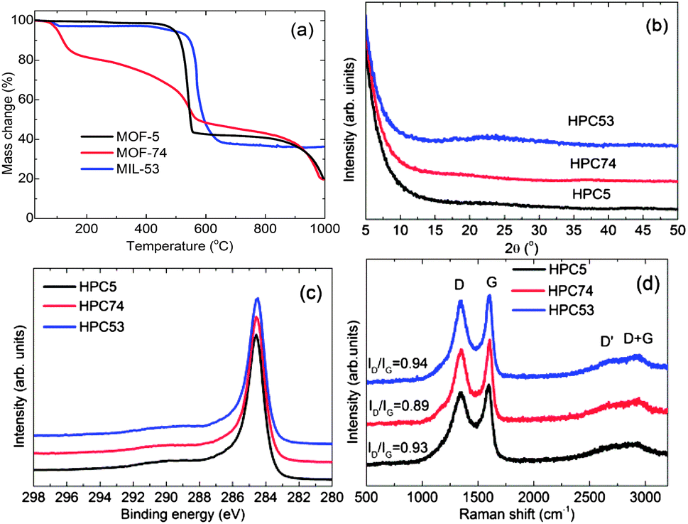
Here, we describe the synthesis and characterisation of highly hierarchical porous carbons (HPCs) for enhanced carbon dioxide capture at high pressure and temperature, up to 30 bar and 75 °C, respectively. This new class of HPCs (HPC5, HPC74, HPC53) are derived from the direct carbonization of three different MOF structures (MOF-5, MOF-74, MIL-53, respectively).12,24,42–44 The carbonization process of one of the MOF precursors, MOF-5 is schematically shown in Scheme 1. HPCs essentially consist of local defective carbon structures with mainly sp2 bonding. We also show that these new materials exhibit simultaneously high surface areas, up to 2734 m2 g−1, and hierarchical pores (micro, meso (>2 nm) and macro (>50 nm)) with very high total pore volumes, up to 5.53 cm3 g−1, achieved by controlling synthesis conditions of the MOF precursors. Such porosity characteristics of simultaneously high surface area and pore volume are seldom found in the family of highly porous carbons. Due to the exceptional porous properties, the HPCs exhibit high CO2 adsorption capabilities, particularly at high-pressure, compared with their parent MOFs and other high surface area porous carbons. Thus the HPCs are ideal sorbents for pre-combustion CO2 capture.
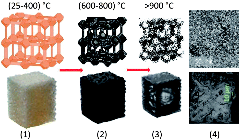 | ||
| Scheme 1 Schematic illustration for steps in fabricating HPCs from a precursor MOF-5; (1) MOF framework/crystal structure (up to 400 °C) with well-defined pore structure in the micropore region, (2) decomposition, and metal-oxide formation, ZnO and carbon between 600 and 800 °C yielding poor pore development, (3) at >900 °C, ZnO reduction and evaporation of Zn and CO yields highly porous carbon with a hierarchical pore structure and (4) surface morphology of HPCs by TEM & SEM. | ||
The prototype framework structures of the MOF precursors are schematically shown in Fig. 1. In our study, all the MOFs were synthesized by the solvothermal method according to the literature and the references therein (see the ESI† for detailed experimental procedure).42–44 As shown in Fig. 1, in the case of MOF-5, a modification in the synthesis conditions resulted in millimetre-sized crystals (batch 2) with enhanced yield (∼140 wt%) compared to the micron-sized crystals from the regular method (batch 1) (Fig. S1†). The powder X-ray diffraction (XRD) patterns (Fig. S2a†), and N2 adsorption isotherms (Fig. S2b†) measured at liquid nitrogen temperature on the MOFs reveal well ordered, and crystalline pore structures, in very good agreement with the earlier reports.42–44 The surface area and pore volume values are summarized in Table 1.
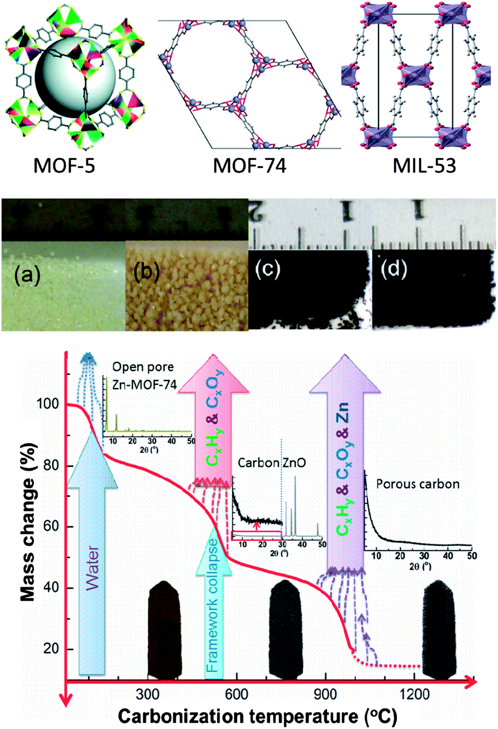 | ||
| Fig. 1 Top: schematic representation of MOF-5,42 MOF-74 and MIL-53 framework structures. Middle: digital photographs of MOF-5 and its carbon (carbonized at 1000 °C) crystals: (a) batch 1, (b) batch 2, (c) HPC5b1-1000 and (d) HPC5b2-1000. Bottom: mechanism involved in the carbonization process of Zn-MOF-74. The plot represents the MOF mass change vs. carbonization temperature. | ||
| Sample | BET surface area (m2 g−1) | Total pore volume (cm3 g−1) | Pure CO2 | Flue CO2 | ||
|---|---|---|---|---|---|---|
| PSA (mmol g−1) | VSA (mmol g−1) | PSA (mmol g−1) | VSA (mmol g−1) | |||
| HPC5b2-1100 | 2734 | 5.23 | 7.33 | 3.78 | 2.44 | 1.4 |
| HPC5b2-1000 | 2517 | 5.53 | 7.01 | 3.93 | 2.52 | 1.5 |
| HPC5b2-900 | 2495 | 5.41 | 6.97 | 4.00 | 2.60 | 1.5 |
| HPC5b1-1000 | 2462 | 3.79 | 6.62 | 3.79 | 2.49 | 1.4 |
| HPC5b1-900 | 2109 | 3.26 | 5.36 | 3.23 | 2.12 | 1.4 |
| HPC74-1000 | 1900 | 1.00 | 5.59 | 3.88 | 2.52 | 1.6 |
| HPC74-900 | 1828 | 0.95 | 5.37 | 3.76 | 2.37 | 1.5 |
| HPC74-800 | 1574 | 1.48 | 4.50 | 3.67 | 2.29 | 1.7 |
| HPC74-600 | 1269 | 1.31 | 4.82 | 3.12 | 2.00 | 1.5 |
| HPC53-1000 | 1260 | 2.47 | 3.49 | 1.96 | 1.29 | 0.7 |
| MOF-5-b1 | 3224 | 1.31 | 4.52 | 1.16 | 0.77 | 0.2 |
| MOF-74 | 1000 | 0.40 | 3.83 | 5.60 | 3.67 | 2.8 |
| MIL-53 | 1193 | 0.44 | 2.57 | 1.98 | 1.42 | 1.2 |
The HPCs were obtained by the direct carbonization of MOFs at temperatures between 600 °C and 1100 °C under N2 atmosphere. The carbonization process and mechanism for Zn-MOF-74 is schematically presented in Fig. 1 and is shown through state-of-the-art simultaneous thermogravimetric analysis (TGA) and mass spectroscopy (MS) (Fig. 2a and S3a–S3c†) for all of the MOFs. The first mass-loss, below 150 °C, is due to the evaporation of adsorbed/terminal water molecules within the pores and the second mass-loss between 400 °C and 600 °C, is attributed to the framework decomposition leading to a major release of carbon containing gaseous products (mostly CO2, CO, C6H6 and a small amount of H2 and CxHy hydrocarbon mixtures) and formation of metal-oxides (ZnO and Al2O3) occurs. The third mass-loss seen in MOF-5 and MOF-74 starting at ∼900 °C is due to further release of CO2 and CO with Zn through the reduction of ZnO by carbon via ZnO + C → Zn(g) + CO.
 | ||
| Fig. 2 (a) TGA plots for the MOF precursors; and (b) powder XRD patterns, (c) C 1s core level XPS spectra, (d) Raman spectra for the HPCs (HPC5b1-1000, HPC74-1000, HPC53-1000). | ||
The carbonization yields materials with either a featureless XRD pattern (Fig. 2b) or very weak and broad XRD peaks between 20° and 25°, and at ∼45° of two-theta (Fig. S4†), indicating the disorderly oriented tiny graphenic type fragments in the structures. It is worth noting that the reduction of ZnO by carbon during carbonization yields a pure porous carbon, whereas MIL-53 (Al) derived carbon always contains metal particles (Fig. S3 and S4†). The X-ray photoemission spectroscopy (XPS) C 1s core level spectra shown in Fig. 2c indicate that the HPCs are graphenic in nature with a majority of sp2 carbons.20 Clearly no Zn is detected in Zn 2p core level XPS spectra in samples obtained at ≥900 °C carbonization or after acid treatment (Fig. S4c†). The broad and highly intense disorder-induced D-band and featureless second-order bands between 2600 cm−1 and 2900 cm−1 in the Raman spectra (Fig. 2d and S4d†) represent the highly disordered/defective or porous nature of the HPCs.28,45 The SEM images and digital photographs presented in Fig. 1, 3, S1 and S5† reveal that the HPCs retain mostly similar crystallite shapes and surface structures to their MOF precursors. It is also noted that the parent MOF crystallites shrink after carbonization as evident from the microcracks and the sponge-like surface morphology.34 Furthermore, the transmission electron microscopy (TEM) images shown in Fig. 4 clearly reveals the highly defective, randomly oriented graphenic type porous carbon.
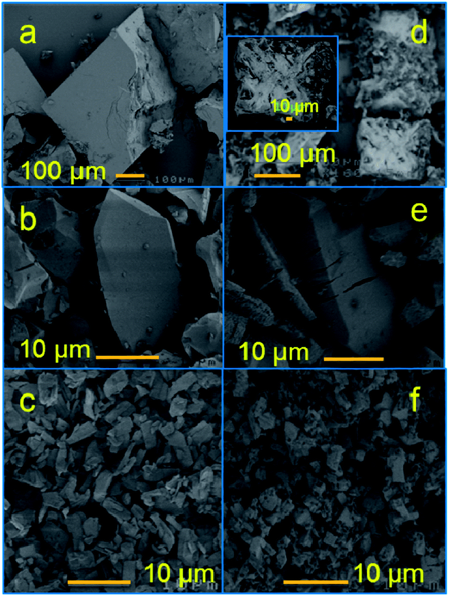 | ||
| Fig. 3 SEM images of (a) MOF-5b1, (b) MOF-74, (c) MIL-53 and their HPCs; (d) HPC5b1-1000, (e) HPC74-1000, (f) HPC53-1000. | ||
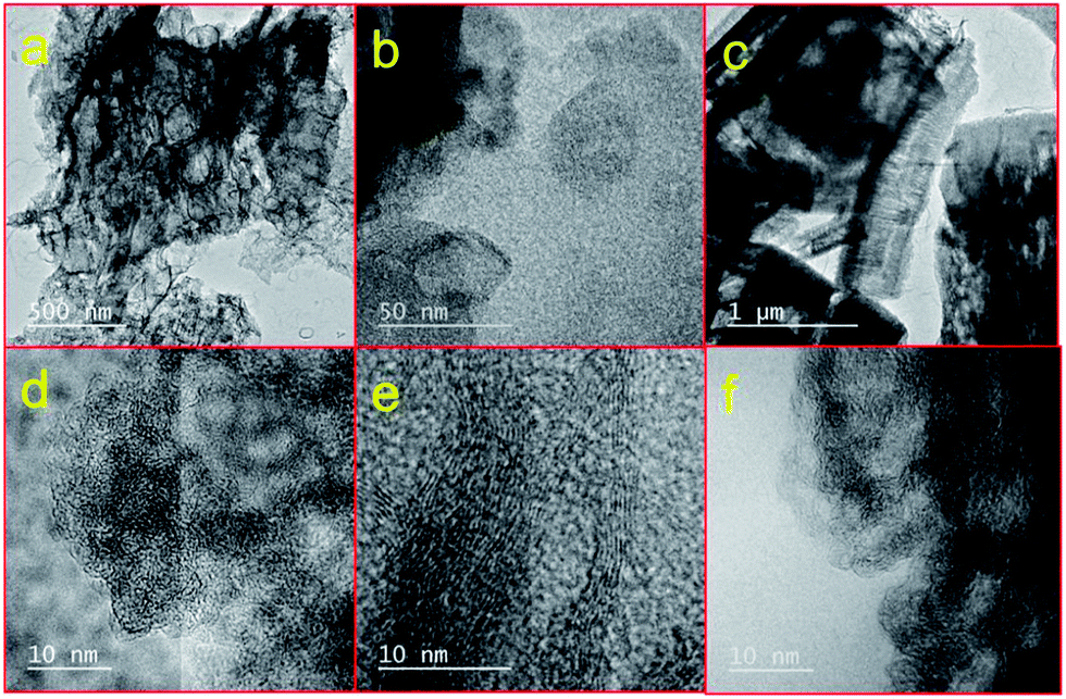 | ||
| Fig. 4 TEM images of HPC5b2-1000 (a and d), HPC74-1000 (b and e) and HPC53-1000 (c and f). (a–c) and (d–f) represent low and high magnification respectively. | ||
The BET surface area and pore volume values for the HPCs and MOFs were obtained from the nitrogen adsorption–desorption isotherms (Fig. 5a, S2 and S6–S8†) and are listed in Table 1 and S1.† The qualitative behaviour of the isotherms (Langmuir or type- I for micropores and S-shaped or type-II for micro–meso–macropores) represents hierarchical pores with dominant microporosity in HPC74 and a large fraction of mesopores in HPC5s. Figs. S6–S8† represent the pore size distribution and cumulative pore volume plots, obtained by the QSDFT and BJH methods. It is worth noting that the HPCs show a considerable enhancement in their total pore volumes compared with their MOF precursors. The total pore volumes between 5.23 cm3 g−1 and 5.53 cm3 g−1 in HPC5b2s are some of the highest values reported so far for porous carbons.23,34,38,46–53 It is important to note that the HPC5b2s also show simultaneously high surface areas between 2495 m2 g−1 and 2734 m2 g−1. Such combination of properties (simultaneously large total pore volume and high surface area) is unique for MOF derived porous carbons and has not been observed yet in any other type of porous carbons. A few of the carbons show pore volumes over 5 cm3 g−1 but with surface areas limited to well below 2000 m2 g−1 or vice versa.23,34,38,46–53 We also note that the measured total pore volumes of over 5 cm3 g−1 in HPC5b2s are the highest among MOF derived porous carbons reported so far (Table S2† and references therein).34,47,48,53 The highest reported values were 4.3 cm3 g−1 and ∼4 cm3 g−1 in Al-MOF and MOF-5 derived carbons, respectively.47,48,53 However, the surface area and total pore volume of HPC5b1s are well within the range of literature values (Table S2†).
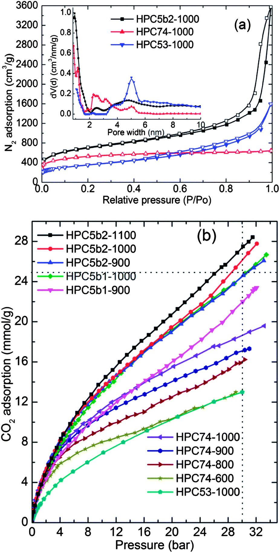 | ||
| Fig. 5 (a) N2 adsorption–desorption isotherms of HPCs measured at −196 °C. Inset shows the QSDFT pore size distribution plots. (b) CO2 adsorption isotherms of HPCs measured at 27 °C. The numbers between 600 and 1100 represent the carbonization temperature in °C. HPC74-600, HPC74-800, and HPC53-1000 are after acid treatment. | ||
The hierarchical pore formation in the HPCs is understandable from their pre-defined well-ordered pore structures of MOF precursors and combined TGA-MS measurements. During the carbonization process (≥900 °C), considerable C and O mass-loss occurs from the framework ligands through the reduction of ZnO that leads to the evolution of Zn, CO and CO2, leaving a more defective or hollow carbon network. This process is a simple self-activation for the carbon, similar to the well-known physical or chemical activation of the carbonaceous precursors with either CO2 or KOH to achieve porous activated carbons.11,19,33 The simultaneously enhanced surface area and pore volume in HPC5b2 are attributed to the large, millimetre-sized crystallites of the MOF precursor, that leaves more void space due to the extended pores within the crystals after carbonization, compared with the smaller crystals in HPC5b1. The influence of the crystallite size of the MOF-5 precursor on the porosity parameters is clearly observed in Fig. S6† and Table 1. Similarly, the framework structure, metal-centres and initial porosity properties of the MOF precursor plays a crucial role in developing desirable porosity in HPCs. The low-density, spherical pore structure and cubic crystallites of the MOF-5 precursor always yield high porosity in the HPCs. However, the carbons derived from Zn-MOF-74 of densely packed, one dimensional pore channels and lower surface area contain a high proportion of micro and mesoporosity. Thus designing and developing of desirable HPCs is not straight forward. The best example in this case is carbons obtained from the MIL-53(Al and Fe) (Fig. S8†). The MIL-53(Fe) derived carbon exhibits very poor porosities with a surface area of only 138 m2 g−1 and a pore volume of 0.22 cm3 g−1. Clearly the MOF framework structure acts as a self-template, thus the microporosity from the MOFs is mostly retained in the derived HPCs and the meso- and macro-pores are generated by reduction of ZnO with carbon and by evolution of Zn, CO and CO2. In the case of MIL-53(Fe), the high solubility of carbon in the reduced Fe particles eventually results in growth of graphitic fibre-like structures with poor porosity (see Fig. S8d† for XRD and SEM images).
The CO2 adsorption–desorption isotherms were measured at several different temperatures between (−53–47) °C and pressure, up to ∼30 bar on HPCs (Fig. 5b and S9–S10†) and on their MOF precursors (Fig. S11†). The isotherm data obtained on the MOFs is in good agreement with the results published in the literature.42–44 HPCs with their hierarchical pores (micro, meso and macro) and large pore volumes clearly show enhanced CO2 uptake at high pressures, up to 30 bar without any indication of saturation. The HPCs also show considerable enhancement of CO2 uptake in the low-pressure region, compared to the coordinatively saturated MOF-5 and MIL-53 precursors due to their small slit-pores.17,38–41,54 The uptake values at low-pressure in MOFs and HPCs correlate well with the initial heat of adsorption (Fig. S11† and ref. 43). The isosteric heat of adsorption in HPCs shows moderate to strong interaction energies. The large mesopore fraction in HPC5 and HPC53 shows a low heat of adsorption.
As shown in Fig. 5b and 6, the measured high-pressure CO2 uptake capacities of over 25 mmol g−1 and a maximum of 27.4 mmol g−1 at 30 bar and 27 °C in our HPCs is one of the highest uptake values reported for highly porous carbons.14,16,18,21–23,31,32,37,55 Furthermore, the room temperature CO2 uptake in the HPCs at 30 bar show a more or less linear relationship with their BET surface area: a CO2 uptake of 10 mmol g−1 for every 1000 m2 g−1 of surface area. A linear relation between CO2 uptake at moderate pressure (6 bar) and the micropore volume is also observed (Fig. S12†). In addition, we also show a comparison of 27 °C CO2 uptake at 1 bar and 30 bar in the present HPCs and other highly porous carbons with surface areas of ≥2000 m2 g−1 (Fig. 6a) and CO2 uptake isotherms in a wide pressure range for porous carbons with surface areas of ≥3000 m2 g−1 in Fig. 6b.14,16,18,21–23,27,31,32,37,55 Clearly, the HPCs show superior CO2 uptakes over other porous carbons. Moreover, the CO2 adsorption in the HPCs with surface areas between 2000 m2 g−1 and 2700 m2 g−1 are better than or comparable to the porous carbons with surface areas higher than 3000 m2 g−1. It is also worth noting that no correlation is found between BET surface area and CO2 uptake at 30 bar for various types of other carbons. This can be primarily attributed to the large differences in their pore volumes as listed in Table S3.† The best example for this case is gas uptake in the well-defined pore structure MOFs (see Fig. S11†). The limited pore volume and pore-filling effect leads no further gas uptake at high pressure. In the HPCs, the hierarchical mesoporosity could play an additional role in obtaining higher CO2 adsorption in the high-pressure region by multilayer adsorption within the pores (see ESI†). Furthermore, it is anticipated that the carbons with a higher micropore volume perform better for CO2 adsorption at 1 bar, because of a large caging effect, particularly those smaller than 1 nm.17,39,56 For example, highly microporous carbon spheres show good CO2 capture performance, over 4 mmol g−1 at 1 bar and 25 °C.56 However, HPCs dominated by hierarchical mesoporosity show CO2 adsorption of ∼3.0 mmol g−1 at ≤1 bar and 27 °C, but their much superior performance at relatively high CO2 pressures makes them a preferred choice for pre-combustion PSA applications.43,57 We listed the adsorptive capacities for both the MOF precursors and the HPCs, along with other high surface area carbons, in Table 1 and S3† for possible PSA/VSA conditions in the case of pure CO2 and flue gas (20% CO2) at 27 °C.43,56 In Table S3,† we also list the surface areas, total pore volumes and high-pressure PSA adsorption values for similar materials reported in the literature. Here it is noted that the total pore volumes between 3.26 cm3 g−1 and 5.53 cm3 g−1 in our HPCs are the highest among the listed carbons.
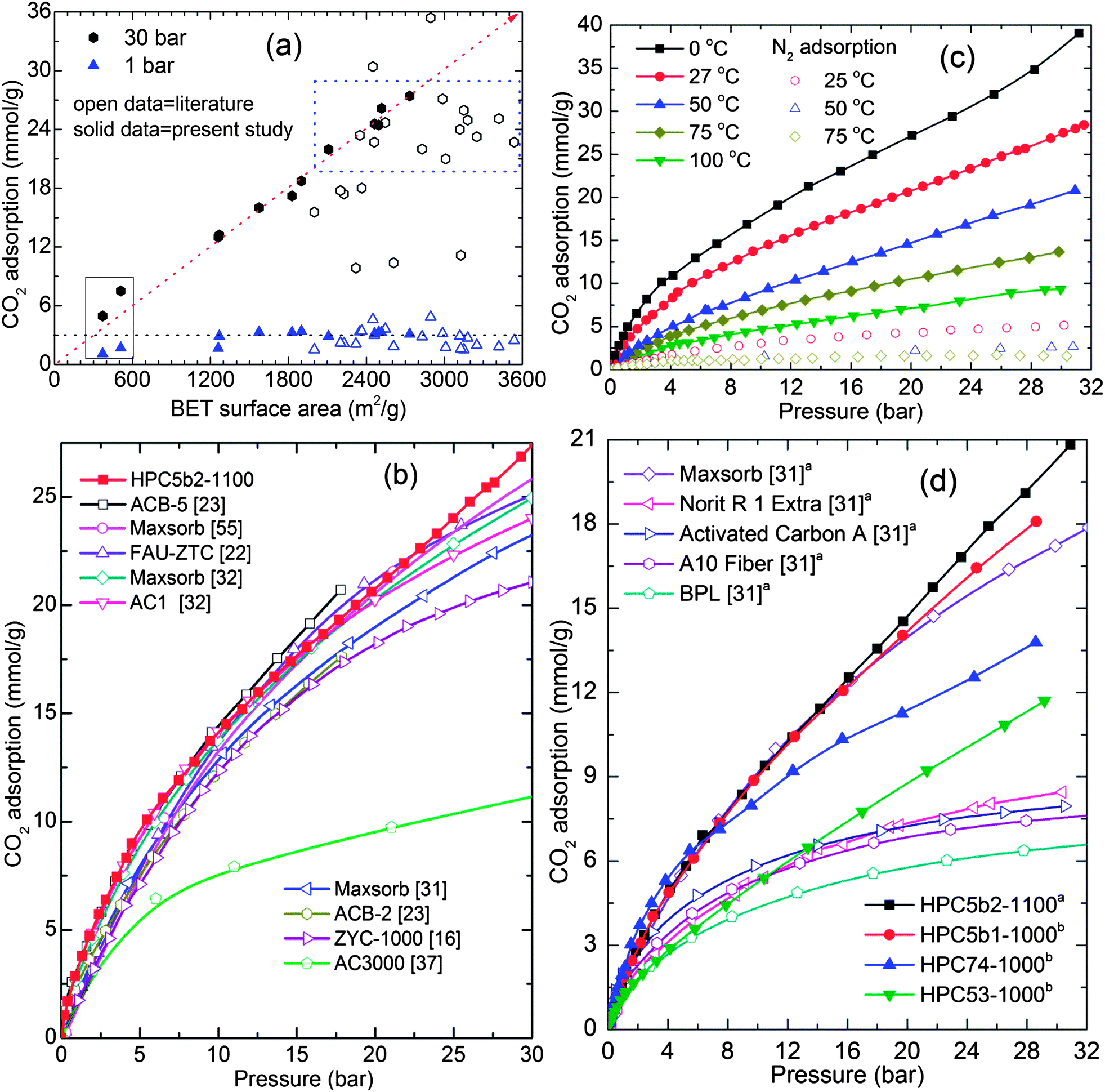 | ||
| Fig. 6 (a and b) represent the comparative CO2 adsorption at (25–27) °C: (a) CO2 adsorption against BET surface area of HPCs and various porous carbons with surface area ≥2000 m2 g−1. (b) Isotherms of various porous carbons with surface area ≥3000 m2 g−1 and HPC5b2-1100 with 2734 m2 g−1. The diagonal dotted line represents a linear relationship between the surface area and CO2 uptake for HPCs. The horizontal dotted line at 3 mmol g−1 is the CO2 uptake at 1 bar. The dotted box exemplifies the CO2 performance of HPCs to that of carbons with ≥3000 m2 g−1 in the literature. The data under the solid line box is from as-synthesized HPC74-600 and HPC74-800 samples. (c) CO2 and N2 adsorption in MOF5b2-1100 sample measured in the temperature range of (0–100) °C, and (d) compares the CO2 adsorption performance of our HPC5b2-1100 sample, represented by superscript a, with commercial carbons at 50 °C. The CO2 adsorption performance of HPC5b1-1000, HPC74-1000 and HPC53-1000 are at 47 °C, represented by superscript b. Note: in ref. 37, the isotherm on the AC3000 sample was obtained without outgassing, therefore the adsorption capacity is underestimated. | ||
As pre- and post-combustion CO2 capture temperature conditions fall between 40 °C and 75 °C,6 we show high-pressure pure component CO2 and N2 adsorption performance of the HPC5b2-1100 above room temperature, (0–100) °C in Fig. 6c. Fig. 6d and S13† also compare the 50 °C and 75 °C isotherms of the HPCs with commercial carbons; such as maxsorb with a BET surface area of 3250 m2 g−1, Norit R1 (1450 m2 g−1) and BPL (1150 m2 g−1), etc.27,31 Clearly the present HPCs still absorb considerable amounts of CO2 and outperform the commercial activated carbons at elevated pressures. We also note that the CO2 adsorption of 5.7 mmol g−1 in the HPC5b2-1100 sample at 75 °C and 7.4 bar is much higher than the recently reported highest CO2 adsorption of 4.3 mmol g−1 under identical experimental conditions in polyethyleneimine impregnated sandwich-like graphene–silica sheets.58
Conclusions
A new group of highly hierarchical porous carbons with high surface areas up to 2734 m2 g−1 and high total pore volumes up to 5.53 cm3 g−1 have been synthesised by tailored carbonization of various MOFs. The HPCs are highly sp2-bonded graphenic in nature with a high portion of defective carbon structures. In most cases, the CO2 uptakes in HPCs are higher than in their MOF counterparts. The high pressure CO2 uptake of over 27 mmol g−1 at 30 bar and 27 °C in HPCs is one of the largest reported in the literature for porous carbons. There seems to be a direct relationship between the CO2 adsorption capacity and the surface area: a CO2 uptake of 10 mmol g−1 for every 1000 m2 g−1 increase of surface area under 30 bar and 27 °C. Due to their thermal/chemical stability and enhanced CO2 capture performance the HPCs are preferred over their counterpart MOFs for the PSA/VSA applications. Finally we note that the selection of a MOF structure and the process conditions play a critical role in obtaining the desirable porosities in the carbons. The present results also suggest that MOF derived hierarchical porous carbons may be favourably considered for other energy related applications, such as lithium-ion adsorption–desorption in battery and supercapacitor electrodes, as well as in methane storage.Acknowledgements
This work was partially supported by the DOE through BES grant no. DE-FG02-08ER46522 (V. K. and T. Y.) and EPSRC grant no. (EP/G061785/1; EP/G063176/1).Notes and references
- V. Scott, S. Gilfillan, N. Markusson, H. Chalmers and R. S. Haszeldine, Nat. Clim. Change, 2013, 3, 105 CrossRef CAS.
- K. S. Lackner, S. Brennan, J. M. Matter, A.-H. A. Park, A. Wright and B. van der Zwaan, Proc. Natl. Acad. Sci. U. S. A., 2012, 109, 13156 CrossRef CAS PubMed.
- T. C. Drage, C. E. Snape, L. A. Stevens, J. Wood, J. Wang, A. I. Cooper, R. Dawson, X. Guo, C. Satterley and R. Irons, J. Mater. Chem., 2012, 22, 2815 RSC.
- P. Markewitz, W. Kuckshinrichs, W. Leitner, J. Linssen, P. Zapp, R. Bongartz, A. Schreiber and T. E. Muller, Energy Environ. Sci., 2012, 5, 7281 CAS.
- S. Choi, J. H. Drese and C. W. Jones, ChemSusChem, 2009, 2, 796 CrossRef CAS PubMed.
- D. M. D'Alessandro, B. Smit and J. R. Long, Angew. Chem., Int. Ed., 2010, 49, 6058 CrossRef CAS PubMed.
- A. Samanta, A. Zhao, G. K. H. Shimizu, P. Sarkar and R. Gupta, Ind. Eng. Chem. Res., 2012, 51, 1438 CrossRef CAS.
- S. Wang, S. Yan, X. Ma and J. Gong, Energy Environ. Sci., 2011, 4, 3805 CAS.
- X. Zhang, X. Zhang, H. Dong, Z. Zhao, S. Zhang and Y. Huang, Energy Environ. Sci., 2012, 5, 6668 CAS.
- Y. Liu, Z. U. Wang and H.-C. Zhou, Greenhouse Gases: Sci. Technol., 2012, 2, 239 CrossRef CAS.
- G. Srinivas, J. Burress and T. Yildirim, Energy Environ. Sci., 2012, 5, 6453 CAS.
- K. Sumida, D. L. Rogow, J. A. Mason, T. M. McDonald, E. D. Bloch, Z. R. Herm, T.-H. Bae and J. R. Long, Chem. Rev., 2012, 112, 724 CrossRef CAS PubMed.
- Z. Zhang, Y. Zhao, Q. Gong, Z. Li and J. Li, Chem. Commun., 2013, 49, 653 RSC.
- J. P. Marco-Lozar, M. Kunowsky, F. Suarez-Garcia, J. D. Carruthers and A. Linares-Solano, Energy Environ. Sci., 2012, 5, 9833 CAS.
- M. Sevilla and A. B. Fuertes, Energy Environ. Sci., 2011, 4, 1765 CAS.
- H.-K. Youn, J. Kim, G. Chandrasekar, H. Jin and W.-S. Ahn, Mater. Lett., 2011, 65, 1772 CrossRef CAS PubMed.
- V. Presser, J. McDonough, S.-H. Yeon and Y. Gogotsi, Energy Environ. Sci., 2011, 4, 3059 CAS.
- Z. Zhang, M. Xu, H. Wang and Z. Li, Chem. Eng. J., 2010, 160, 571 CrossRef CAS PubMed.
- M. Nandi, K. Okada, A. Dutta, A. Bhaumik, J. Maruyama, D. Derks and H. Uyama, Chem. Commun., 2012, 48, 10283 RSC.
- J. W. Burress, S. Gadipelli, J. Ford, J. M. Simmons, W. Zhou and T. Yildirim, Angew. Chem., Int. Ed., 2010, 49, 8902 CrossRef CAS PubMed.
- J. Silvestre-Albero, A. Wahby, A. Sepulveda-Escribano, M. Martinez-Escandell, K. Kaneko and F. Rodriguez-Reinoso, Chem. Commun., 2011, 47, 6840 RSC.
- S. Builes, T. Roussel, C. M. Ghimbeu, J. Parmentier, R. Gadiou, C. Vix-Guterl and L. F. Vega, Phys. Chem. Chem. Phys., 2011, 13, 16063 RSC.
- X. Shao, Z. Feng, R. Xue, C. Ma, W. Wang, X. Peng and D. Cao, AIChE J., 2011, 57, 3042 CrossRef CAS.
- J.-R. Li, Y. Ma, M. C. McCarthy, J. Sculley, J. Yu, H.-K. Jeong, P. B. Balbuena and H.-C. Zhou, Coord. Chem. Rev., 2011, 255, 1791 CrossRef CAS PubMed.
- H. Furukawa, N. Ko, Y. B. Go, N. Aratani, S. B. Choi, E. Choi, A. O. Yazaydin, R. Q. Snurr, M. O'Keeffe, J. Kim and O. M. Yaghi, Science, 2010, 329, 424 CrossRef CAS PubMed.
- Y. Peng, G. Srinivas, C. E. Wilmer, I. Eryazici, R. Q. Snurr, J. T. Hupp, T. Yildirim and O. K. Farha, Chem. Commun., 2013, 49, 2992 RSC.
- C. A. Grande, R. Blom, A. Moller and J. Mollmer, Chem. Eng. Sci., 2013, 89, 10 CrossRef CAS PubMed.
- G. Srinivas, Y. Zhu, R. Piner, N. Skipper, M. Ellerby and R. Ruoff, Carbon, 2010, 48, 630 CrossRef CAS PubMed.
- H.-L. Jiang, B. Liu, Y.-Q. Lan, K. Kuratani, T. Akita, H. Shioyama, F. Zong and Q. Xu, J. Am. Chem. Soc., 2011, 133, 11854 CrossRef CAS PubMed.
- V. Chandra, S. U. Yu, S. H. Kim, Y. S. Yoon, D. Y. Kim, A. H. Kwon, M. Meyyappan and K. S. Kim, Chem. Commun., 2012, 48, 735 RSC.
- S. Himeno, T. Komatsu and S. Fujita, J. Chem. Eng. Data, 2005, 50, 369 CrossRef CAS.
- J. P. Marco-Lozar, J. Juan-Juan, F. Suárez-García, D. Cazorla-Amorós and A. Linares-Solano, Int. J. Hydrogen Energy, 2012, 37, 2370 CrossRef CAS PubMed.
- H. Marsh and F. Rodríguez-Reinoso, Activated carbon, Elsevier, London, 2006 Search PubMed.
- W. Chaikittisilp, K. Ariga and Y. Yamauchi, J. Mater. Chem. A, 2013, 1, 14 CAS.
- M. Sevilla and A. B. Fuertes, J. Colloid Interface Sci., 2012, 366, 147 CrossRef CAS PubMed.
- W. Shen, S. Zhang, Y. He, J. Li and W. Fan, J. Mater. Chem., 2011, 21, 14036 RSC.
- T. C. Drage, J. M. Blackman, C. Pevida and C. E. Snape, Energy Fuels, 2009, 23, 2790 CrossRef CAS.
- E. Masika and R. Mokaya, J. Phys. Chem. C, 2012, 116, 25734 CAS.
- Z. Zhang, J. Zhou, W. Xing, Q. Xue, Z. Yan, S. Zhuo and S. Z. Qiao, Phys. Chem. Chem. Phys., 2013, 15, 2523 RSC.
- G. Srinivas, J. W. Burress, J. Ford and T. Yildirim, J. Mater. Chem., 2011, 21, 11323 RSC.
- G. Yushin, R. Dash, J. Jagiello, J. E. Fischer and Y. Gogotsi, Adv. Funct. Mater., 2006, 16, 2288 CrossRef CAS.
- W. Zhou, H. Wu, M. R. Hartman and T. Yildirim, J. Phys. Chem. C, 2007, 111, 16131 CAS.
- J. M. Simmons, H. Wu, W. Zhou and T. Yildirim, Energy Environ. Sci., 2011, 4, 2177 CAS.
- S. Bourrelly, P. L. Llewellyn, C. Serre, F. Millange, T. Loiseau and G. Ferey, J. Am. Chem. Soc., 2005, 127, 13519 CrossRef CAS PubMed.
- G. Srinivas, C. A. Howard, S. M. Bennington, N. T. Skipper and M. Ellerby, J. Mater. Chem., 2009, 19, 5239 RSC.
- Z. Wen, X. Wang, S. Mao, Z. Bo, H. Kim, S. Cui, G. Lu, X. Feng and J. Chen, Adv. Mater., 2012, 24, 5610 CrossRef CAS PubMed.
- S. J. Yang, T. Kim, J. H. Im, Y. S. Kim, K. Lee, H. Jung and C. R. Park, Chem. Mater., 2012, 24, 464 CrossRef CAS.
- M. Hu, J. Reboul, S. Furukawa, N. L. Torad, Q. Ji, P. Srinivasu, K. Ariga, S. Kitagawa and Y. Yamauchi, J. Am. Chem. Soc., 2012, 134, 2864 CrossRef CAS PubMed.
- D. Li, F. Han, S. Wang, F. Cheng, Q. Sun and W.-C. Li, ACS Appl. Mater. Interfaces, 2013, 5, 2208 CAS.
- M. A. Worsley, T. Y. Olson, J. R. I. Lee, T. M. Willey, M. H. Nielsen, S. K. Roberts, P. J. Pauzauskie, J. Biener, J. H. Satcher Jr and T. F. Baumann, J. Phys. Chem. Lett., 2011, 2, 921 CrossRef CAS.
- R. Wang, P. Wang, X. Yan, J. Lang, C. Peng and Q. Xue, ACS Appl. Mater. Interfaces, 2012, 4, 5800 CAS.
- C. X. Guo, Y. Wang and C. M. Li, ACS Sustainable Chem. Eng., 2013, 1, 14 CrossRef CAS.
- K. Xi, S. Cao, X. Peng, C. Ducati, R. V. Kumar and A. K. Cheetham, Chem. Commun., 2013, 49, 2192 RSC.
- X. Hu, M. Radosz, K. A. Cychosz and M. Thommes, Environ. Sci. Technol., 2011, 45, 7068 CrossRef CAS PubMed.
- B. B. Saha, S. Jribi, S. Koyama and I. I. El-Sharkawy, J. Chem. Eng. Data, 2011, 56, 1974 CrossRef CAS.
- N. P. Wickramaratne and M. Jaroniec, ACS Appl. Mater. Interfaces, 2013, 5, 1849 CAS.
- M. T. Ho, G. W. Allinson and D. E. Wiley, Ind. Eng. Chem. Res., 2008, 47, 4883 CrossRef CAS.
- S. Yang, L. Zhan, X. Xu, Y. Wang, L. Ling and X. Feng, Adv. Mater., 2013, 25, 2130 CrossRef CAS PubMed.
Footnote |
| † Electronic supplementary information (ESI) available: Experimental details and further characterizations; XRD, XPS, MS, SEM, BET surface area N2 isotherms, and high-pressure CO2 uptake are given. See DOI: 10.1039/c3ee42918k |
| This journal is © The Royal Society of Chemistry 2014 |