DOI:
10.1039/C2RA20675G
(Paper)
RSC Adv., 2012,
2, 7569-7577
Morphology-controllable synthesis and enhanced luminescence properties of β-NaLuF4:Ln (Ln = Eu, Tb and Ce/Tb) microcrystals by solvothermal process†
Received
13th April 2012
, Accepted 11th June 2012
First published on 13th June 2012
Abstract
Controlled synthesis of β-NaLuF4 with uniform morphology, dimension and considerable monodispersity was designed via a gentle solvothermal process by using ethylenediamine (EDA) and ethylene glycol (EG) as the mixed solvent and NaNO3 as a mineralizer. X-ray diffraction (XRD), field scanning electron microscopy (FESEM), transmission electron microscopy (TEM), high-resolution transmission electron microscopy (HRTEM), energy dispersive X-ray spectra (EDS) and down-conversion (DC) photoluminescence spectra were used to characterize the samples. The results indicate that the as-prepared β-NaLuF4 microcrystals can be rationally modified in phase, size and morphology by tuning the solvent constitution, NaNO3 content, and reaction time. Moreover, the crystal growth process was thoroughly discussed through a series of time-dependent experiments and a possible formation mechanism was proposed. Furthermore, the DC luminescence properties as well as the emission mechanisms of β-NaLuF4:Ln3+ (Ln = Eu, Tb and Ce/Tb) microcrystals were systematically investigated. It is found that the DC luminescence properties can be improved observably by introducing Ce3+ into the β-NaLuF4 microcrystals and the doping concentration of the Ce3+ is optimized under a fixed concentration of Tb3+. It is expected that the synthesis strategy can be applied to prepare many other types of micro- and nano-crystals as well.
1. Introduction
In the field of modern materials science and technology, control over crystallization remains the key issue and research focus, due to its potential applications in the preparation of well-defined crystals with uniform shapes and assembly of building blocks into ordered superstructures.1–6 To date, several approaches have been employed to synthesize nano- and microcrystals (NCs and MCs) with uniform phase, dimension and morphology, such as the solid-state combinatorial chemistry method,7,8 the molten-salt approach,9 hydrothermal and solvothermal techniques,10–13 the sol–gel route,14,15 and chemical vapor synthesis.16 In particular, as a typical representative of the solution-based approach, the solvothermal method has proved to be an effective and convenient approach in the precise architectural manipulation of inorganic functional materials with well-defined morphologies and accurately adjustable sizes.17–21 In fact, the solvent under different conditions can not only play a role as the surrounding guest of the reaction, but also chelate with the reactant as a ligand and thus direct the evolution of the structure and morphology of the products. Furthermore, under solvothermal conditions, many starting materials can undergo quite unexpected reactions, which are often accompanied by the formation of nanoscopic morphologies that are not accessible by classical routes. For example, Qian's group synthesized ultra-long Bi2S3 nanoribbons with lengths of up to a few millimeters via a solvothermal method using an aqueous NaOH solution and glycerol as the solvent.22 Yang et al. demonstrated a solvothermal route for the synthesis of high-quality anatase TiO2 single crystals by using 2-propanol as a synergistic capping agent and reaction medium.23 Recently, a solvothermal reduction method has been developed to decrease the number of defects and the oxygen content in graphene sheets and graphite oxide.24 An EDA-assisted solvothermal reaction in an EG solvent has been adopted to fabricate some advanced materials,25,26 where the EG and EDA acted as synergic effects in the solvothermal system to direct the crystal growth process. However, to the best of our knowledge, controlled preparation of luminescent rare-earth fluorides through the EG-EDA solvothermal method has never been reported.
In the past two decades, rare-earth based materials have attracted much research interest because of their novel electronic and optical properties resulting from their 4f electrons.27–31 Among the various rare earth phosphors, β-NaREF4 has received more and more attention for its enormous potential applications in diverse fields, such as solid-state lasers,32,33 3D flat-panel displays,34,35 biological detection,36,37 low-intensity IR imaging,38 sensing39 and so forth. Particularly, β-NaLuF4 nano- and microcrystals have been regarded as excellent host lattices for the down-conversion (DC) and up-conversion (UC) luminescence of lanthanide ions.40,41 In comparison with Y3+, Lu3+ may be more favorable for trivalent lanthanide (Ln3+) dopant emission due to the intensity-borrowing mechanism mixing the 4f and 5d orbitals of the Ln3+ ions via the lattice valence band level.42,43 Moreover, Lu3+ ion doping can also influence the population life time of the emitters, which may, remarkably, tune the luminescence properties (e.g. brightness and long afterglow performance).44,45 However, from previous research, there are always several different excitation points in the DC emission of β-NaLuF4:Ln (Ln = Eu3+, Tb3+) phosphors, which means a relatively low energy transfer efficiency and inconvenience for further applications.41 Recently, several groups doped Ce3+ as the sensitizer in combination with other lanthanide ions as corresponding activators,46–49 which may provide an effective method to solve this problem. From the viewpoint of energy transfer, Ce3+ and Ln co-doped phosphors may generate light more efficiently.50 However, this kind of energy transfer process in the β-NaLuF4 host lattice has rarely been reported so far.
Accordingly, in the present work, we propose a template-free, no-seed solvothermal process for the synthesis of uniform Ln3+ (Ln = Eu, Tb and Ce/Tb) doped β-NaLuF4 MCs with high monodispersity. Ethylene glycol (EG) and ethylenediamine (EDA) was chosen as the solvent in the reaction system to govern the morphology, size and dimension of the products. The effects of the solvent constitution (volume ratio of EG to EDA), NaNO3 content in the initial solution and reaction time on the crystal dimension, structure and morphology have been investigated in detail. It can be found that the size, structure, and morphology of the products can be precisely controlled by modulation of the conditions above, and a possible mechanism of crystal growth has also been proposed. Additionally, the DC luminescence properties of Eu3+, Tb3+ and Ce3+/Tb3+ doped β-NaLuF4 MCs have been thoroughly studied.
2. Experimental section
2.1. Materials
All materials including analytical grade NaNO3, Ce(NO3)3·6H2O, ethylene glycol (EG) and ethylenediamine (EDA) were purchased from Sinopharm Chemical Reagent Co., Ltd and used as received without further purification. Lu(NO3)3, Eu(NO3)3 and Tb(NO3)3 were prepared by dissolving the corresponding Lu2O3, Eu2O3, and Tb4O7 (99.99%, Sinopharm Chemical Reagent Co., Ltd, China) in HNO3 solution at elevated temperature followed by evaporating the superfluous HNO3 and the solvent under vacuum.
2.2. Preparation of β-NaLuF4
All of the doping ratios of Ln3+ are molar in our experiments. In a typical procedure for the preparation of β-NaLuF4:5% Ce3+/2.5% Tb3+ MCs, 0.925 mmol Lu(NO3)3, 0.05 mmol Ce(NO3)3, 0.025 mmol Tb(NO3)3 and 2.5 mmol (0.1 g) NaNO3 were dissolved in a mixed solvent composed of 3 mL EG and 7 mL EDA under ultrasonication. Afterwards, a solution of 12.5 mmol NH4F in 10 mL EDA was added into the above solution under vigorous stirring. After stirring for 30 min, the mixed solution was transferred into a Teflon bottle of volume 30 mL in a stainless steel autoclave, sealed, and maintained at 200 °C for 48 h. As the autoclave cooled to room temperature naturally, the precipitates were separated by centrifugation, washed with deionized water and ethanol in sequence, and then dried in air at 70 °C for 12 h. NaLuF4:2.5% Eu3+, NaLuF4:2.5% Tb3+ and NaLuF4:x% Ce3+/2.5% Tb3+ (x = 2.5, 7.5, 10) samples were prepared in a manner similar to that of β-NaLuF4:5% Ce3+/2.5% Tb3+. Different solvent constitution (volume ratio of EG/EDA = 0![[thin space (1/6-em)]](https://www.rsc.org/images/entities/char_2009.gif) :20, 3:17, 7:13, 10:10, 13:7, 17:3 and only EG as the solvent), differing NaNO3 content (5, 7.5, 10 mmol), different mineralizers (Na2SO4, Na3PO4) and time-dependent experiments (reaction time = 1, 3, 6 h) were employed to study the effects on the morphology, structure and size of the as-synthesized products. It should be pointed out that, when the effect of one reaction condition was studied, the other reaction conditions were kept the same as those for the typical fabrication.
:20, 3:17, 7:13, 10:10, 13:7, 17:3 and only EG as the solvent), differing NaNO3 content (5, 7.5, 10 mmol), different mineralizers (Na2SO4, Na3PO4) and time-dependent experiments (reaction time = 1, 3, 6 h) were employed to study the effects on the morphology, structure and size of the as-synthesized products. It should be pointed out that, when the effect of one reaction condition was studied, the other reaction conditions were kept the same as those for the typical fabrication.
X-ray diffraction (XRD) was examined on a Rigaku-Dmax 2500 diffractometer using Cu-Kα radiation (λ = 0.15405 nm). The XRD samples are prepared by putting the absolute dry NaLuF4 powder on a glass slide substrate and pressed lightly with another glass slide. Analysis of the composition of the metallic elements was performed using inductively coupled plasma (ICP) emission spectroscopy on a Thermal XSeries II in solutions prepared by dissolving the samples in dilute HNO3. The morphology and composition of the as-prepared samples were inspected on a field emission scanning electron microscope (FESEM, S4800, Hitachi) equipped with an energy-dispersive X-ray spectrum (EDS, JEOL JXA-840). The powder samples for EDS analysis were also completed to determine its elemental composition by increasing the accelerating voltage to 25 kV and reducing the working distance to 8.5 mm for an aperture of 30 μm. The EDX elemental composition was determined by comparing relative peak intensities together with the corresponding sensitivity factors of each element and assuming their total intensities to be 100%. Transmission electron microscopy (TEM) and high-resolution transmission electron microscopy (HRTEM) were performed on a FEI Tecnai G2 S-Twin transmission electron microscope with a field emission gun operating at 200 kV to elucidate the dimensions and the structural details of the particles. The photoluminescence (PL) excitation and emission spectra were recorded with a Hitachi F-7000 spectrophotometer equipped with a 150 W xenon lamp as the excitation source. The lifetime measurement was taken by using the third harmonic (355 nm) of a continuum Nd:YAG laser (pulse width = 4 ns, gate = 50 ns) with 5 mJ of energy per pulse as the source, and the emission lines were dispersed by the emission monochromator of the Acton Spectra Pro-2758 equipped with R928 PMT; the data were recorded by using a LeCroy Wave Runner 6100 digital oscilloscope (1 GHz). The luminescence lifetimes were calculated by the Origin 8.5 software package. All the measurements were performed at room temperature.
3. Results and discussion
3.1. Phase, structure and morphology
The composition and phase purity of the sodium lutetium fluoride with different RE3+ ions were first examined by XRD measurement. Fig. 1 demonstrates the XRD patterns of as-prepared β-NaLuF4:2.5% Eu3+, NaLuF4:2.5% Tb3+ and β-NaLuF4:5% Ce3+/2.5% Tb3+ samples. From all three patterns, it is obvious that these samples are highly crystalline, and the diffractions can be readily indexed to the pure β-NaLuF4 phase (JCPDS No. 27-0726). No peaks from other phases or from doping are observed, indicating the high purity and that the Ce3+, Eu3+ and Tb3+ ions have been effectively incorporated into the β-NaLuF4 host by substituting Lu3+ sites. The calculated unit cell lattice constants corresponding to the lattice constants for the two samples are summarized in Table 1. It is found that these values from the crystalline samples are consistent with those from the standard card (JCPDS No. 27-0726). The slightly higher lattice constants may be caused by the larger ionic radius of the substituted Ce3+, Eu3+ and Tb3+. It should be noted that the markedly strengthened intensities of typical peaks may be caused by the preferred growth orientation of the samples.
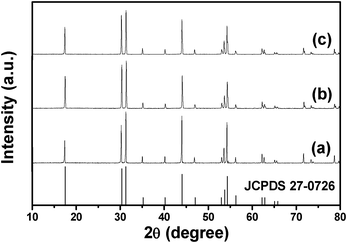 |
| | Fig. 1 XRD patterns of (a) β-NaLuF4:2.5% Eu3+ MCs, (b) β-NaLuF4:2.5% Tb3+ and (c) β-NaLuF4:5% Ce3+/2.5% Tb3+ MCs prepared with NaNO3 content of 0.1 g at 200 °C for 24 h. | |
Table 1 Unit cell lattice constants for hexagonal β-NaLuF4:2.5% Eu3+ MCs, hexagonal β-NaLuF4:2.5% Tb3+ MCs and hexagonal β-NaLuF4:5% Ce3+/2.5% Tb3+ MCs
| Samples |
a (Å) |
c (Å) |
Cell volume (Å3) |
| β-NaLuF4:2.5% Eu3+ |
5.914 |
3.448 |
104.45 |
| β-NaLuF4:2.5% Tb3+ |
5.909 |
3.449 |
104.32 |
| β-NaLuF4:5% Ce3+/2.5% Tb3+ |
5.919 |
3.451 |
104.73 |
| JCPDS No. 27-0726 |
5.901 |
3.453 |
104.13 |
Fig. 2 displays the FESEM, TEM and HRTEM images, and the EDS spectrum of the β-NaLuF4 MCs prepared with an EG/EDA volume ratio of 3:17 at 200 °C for 24 h. It can be seen from Fig. 2a that β-NaLuF4 exhibits a uniform six-sided prismatic structure with good monodispersity and a narrow size distribution. In the high magnification FESEM image (Fig. 2b), the prismatic structure has an average diameter of 1.94 μm and a thickness of 350 nm. The typical TEM image shows the obvious hexagonal microstructure with uniform size distribution (Fig. 2c). It should be noted that no chromatic aberration can be detected on the shadow part of the image, indicating the solid structure of the microplate. Besides, it is obvious that the surfaces on the top/bottom are very rough, which indicates an active growth on the surfaces under the conditions of relatively high temperature and pressure. A new side at the corresponding vertex of the hexagon can be found in the magnified TEM image (Fig. 2d), indicating active growth along the radial direction. The obvious lattice fringes in the HRTEM image (Fig. 2e) confirm the high crystallinity. The distance of 0.29 nm between the adjacent lattice fringes corresponds well to the d110 spacing of the hexagonal NaLuF4 phase (JCPDS No. 27-0726). The EDS analysis (Fig. 2f) confirms the presence of Na, Lu, Ce, Tb and F, and the Na:(Lu + Ce + Tb):F atomic ratio of 1:1.019:4.039 is in good agreement with the theoretical atomic Na:Lu:F ratio (1:1:4). The composition of the sample is further analysed by the ICP measurement; the respective quality percentage compositions of the Na+, Lu3+, Ce3+ and Tb3+ are 8.87, 60.35, 2.11, and 1.01 (corresponding molar ratios: 17.65%, 15.82%, 0.67%, and 0.31%, respectively), which agrees well with the EDS result and further confirms the composition of the NaLuF4 crystals.
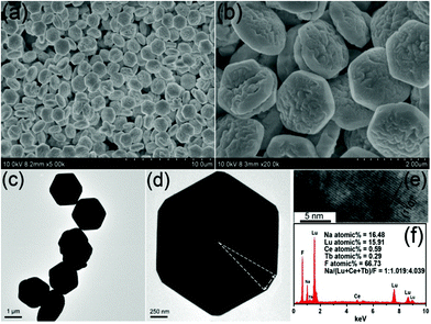 |
| | Fig. 2 Low- and high-magnification FESEM images (a) and (b), TEM images (c) and (d), HRTEM image (e), and EDS (f) of β-NaLuF4 MCs prepared with NaNO3 content of 0.1 g at 200 °C for 24 h. | |
3.2. Influential factors and possible formation mechanism
In the following sections, the effects of the EG/EDA volume ratio, NaNO3 content and reaction time on the crystal structures and shapes of the final products are investigated in detail. Moreover, the possible formation mechanism for β-NaLuF4 MCs with various morphologies is presented.
Effect of EG/EDA volume ratio.
To investigate the effect of the EG/EDA volume ratio on the morphology of NaLuF4 MCs, a series of contrasting experiments were conducted. Fig. 3 shows the FESEM images of β-NaLuF4 MCs prepared with EG/EDA volume ratios of 0:20, 3:17, 7:13 and 10:10, respectively. In Fig. 3a, the crystals prepared with an EG/EDA volume ratio of 0:20 consist of regular and monodisperse hexagonal microplates with rough convex centers on the top/bottom surfaces. In the high magnification FESEM image (Fig. 3b), almost no side face can be discovered in the microplates and the mean diameter is 1.05 μm. Besides, some of the crystals are broken from the center, indicating that the microplates are relatively thin and only grow slightly along the axial direction. By contrast, the crystals synthesized with an EG/EDA volume ratio of 3:17 have further grown along the axial direction and the obvious side faces can be easily detected from Fig. 3c and Fig. 3d. Further increasing the EG/EDA volume ratio to 7:13, the crystal changes to a microprism structure with a diameter of 3.14 μm and a thickness of 1.55 μm, suggesting further growth along both the axial and radial directions (Fig. 3e). Furthermore, close observation (Fig. 3f) reveals that the top/bottom surface of the MCs changes to smooth from the fringe yet the center remains rough. When the EG/EDA volume ratio is enhanced to 10:10, the as-prepared products with a thickness of 2.78 μm exhibit further growth along the axial direction, while the average diameter is decreased to 2.85 μm compared with the last sample. On the basis of the above results, it can be inferred that the size of hexagonal β-NaLuF4 MCs can be regulated by modulating the solvent constitution and increasing the EDA content can cause the structure to evolve from hexagonal microprism to hexagonal microplate. In fact, the capping effect and complexing ability of EDA have been proven by previous teams.51–53 In the present system, EDA chelates with Lu3+ to form the [Lu3+(EDA)m]3+ complex, which may decrease the quantity of free Lu3+ in the solution and strongly influence the crystal growth process, as shown in the following equations.53| | | Lu(NO3)3 + mEDA ↔ [Lu3+(EDA)m]3+ (complex) + 3NO3− | (1) |
| | | Na+ + [Lu3+(EDA)m]3+ + 4F− → NaLuF4 + mEDA | (4) |
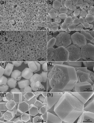 |
| | Fig. 3 Low- and high-magnification FESEM images of β-NaLuF4 MCs prepared at 200 °C for 24 h and in EG/EDA volume ratios of 0:20 (a) and (b), 3:17 (c) and (d), 7:13 (e) and (f), 10:10 (g) and (h). All of the samples were obtained with NaNO3 content of 0.1 g. | |
Besides, due to the anisotropy of the hexagonal β-NaLuF4 structure, the EDA molecules can selectively adsorb on the typical {0001}, namely top/bottom surfaces, which are considered high surface energy and growth-active surfaces. When the EDA content in the solution is high, the strong capping effect on the top/bottom surfaces causes little growth along the axial direction of the crystals. Therefore, the crystals can grow more along the [1010] direction. However, owing to the low surface energy of the {1010} surfaces and the limited free Lu3+, the growth rate on these surfaces is also quite low. So the hexagonal microplates can be obtained under these conditions. When the EDA content in the solution is relatively low, the capping effect and complexing ability of the EDA in the system will be reduced accordingly. As a result, the hexagonal microprisms with greater height and diameter can be synthesized.
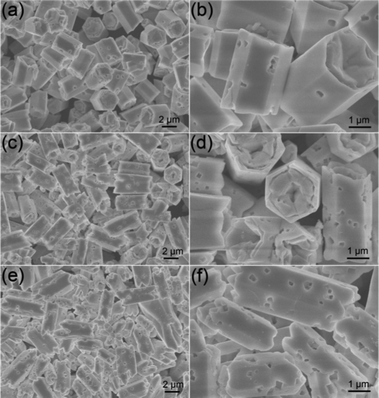
In order to thoroughly investigate the effect of the solvent constitution on the morphology and structure, more widespread experiments have been carried out. Fig. 4 demonstrates the FESEM images of the products synthesized with EDA/EG volume ratios of 7:13, 3:17 and 0:20. In Fig. 4a and b, for the sample fabricated with an EDA/EG volume ratio of 7:13, the product comprises hexagonal microprisms with an average diameter of 1.87 μm and length of 3.52 μm. The remarkable structure transformation can also be explained by the mechanism proposed previously. Under the condition of lower EDA concentration, the crystals can grow more freely and quickly. Consequently, growth on the high energy {0001} surfaces can be promoted immensely and the hexagonal microprisms with high length/diameter ratios can be obtained. Interestingly, by further increasing the EG content (EDA/EG volume ratio = 3:17), the uniform fusiform MCs with an average diameter of 1.96 μm and height of 5.31 μm can be achieved (Fig. 4c). Notably, the magnified image (Fig. 4d) shows that new surfaces have been created on the top/bottom surfaces, which suggests a speedy growth along the axial direction of the fusiform crystals. However, when pure EG was used as the solvent, only some irregular MCs could be found (Fig. 4e). In addition, the magnified image (Fig. 4f) indicates that the top/bottom surfaces of the MCs disappear, and are replaced by some tuber-like layers. The results reveal that EDA plays a very important role in the formation of the hexagonal β-NaLuF4 MCs. By regulating the EDA content in the solvent, the microprisms with different heights and diameters can be obtained. In particular, the regulating process is effective, precise, and can be achieved easily.
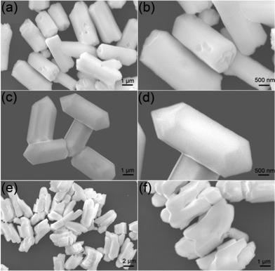 |
| | Fig. 4 Low- and high-magnification FESEM images of β-NaLuF4 MCs prepared at 200 °C for 24 h and EDA/EG volume ratio of 7:13 (a) and (b), 3:17 (c) and (d), and 0:20 (e) and (f). All of the samples were obtained with NaNO3 content of 0.1 g. | |
 |
| | Fig. 5 Low- and high-magnification FESEM images of β-NaLuF4 MCs synthesized at 200 °C for 24 h and differing NaNO3 content of 5 mmol (a) and (b), 7.5 mmol (c) and (d), 10 mmol (e) and (f). All of the samples were obtained with an EDA/EG volume ratio of 10:10. | |
Effect of NaNO3 content.
When the EDA/EG volume ratio was fixed at 10:10, 0.2, 0.3 and 0.4 g NaNO3 were applied to investigate the effect of NaNO3 content on the crystallization and morphology. When the NaNO3 content in the initial solution is 5 mmol, the as-synthesized sample exhibits uniform hexagonal microprisms with the longer length of 3.54 μm and a similar diameter of 2.82 μm (Fig. 5a) than the product prepared with 2.5 mmol NaNO3 (Fig. 3). The high-magnification FESEM image (Fig. 5b) indicates that concave centers on the top/bottom surfaces and a few micropores with diverse diameters are formed on the side surfaces. When more NaNO3 (7.5 mmol) was added to the initial solution, uniform hexagonal microprisms with a longer mean length of 5.15 μm and an approximately equal mean diameter of 2.83 μm can be achieved (Fig. 5c). Moreover, close observation (Fig. 5d) shows that the microprisms with scraggly top/bottom surfaces have more serried micropores on the side surfaces, which means the formation of the rough side surfaces is in relation to the adding of NaNO3. However, when the NaNO3 content was further enhanced to 10 mmol, some irregular MCs with various diameters and lengths can be found and some of them are distorted, as shown in Fig. 5e and Fig. 5f. The mineralization of NaNO3 has been proven by other groups previously.54,55 When the superfluous NaNO3 was added, it could act as a mineralizer and increase the chemical potential of the solution, which may lead to a dissolution–recrystallization process of β-NaLuF4 into the stable phase with a bigger size,56 which will be discussed in the following time-dependent experimental section. Besides, the micropores on the side surfaces may also be formed during this process. Simultaneously, some additional control experiments have been taken by using Na2SO4 and Na3PO4 as the sodium-source and mineralizer. It can be observed from the SEM and XRD results (Fig. S1†) that the as-prepared NaLuF4 crystals are all inhomogenous in morphology, and the sample prepared with Na2SO4 is a mixed phase, which is possibly due to the low solubility of Na2SO4 and Na3PO4 in EG and EDA. In this work, regular microprisms with uniform size and micropore structure could only be obtained with suitable NaNO3 content.
Effect of reaction time.
Fig. 6 gives the XRD patterns and FESEM images of the samples prepared with reaction times of 1 h, 3 h and 6 h, respectively. In Fig. 6a, the XRD pattern of the sample prepared with a reaction time of 1 h (red line) shows some impure peaks according to the β-NaLuF4 standard card (JCPDS No. 27-0726). The excrescent peaks can be assigned to the Na5Lu9F32 phase (JCPDS No. 27-0725) by further analysis. When the reaction time is increased to 3 h, the intensities of the diffraction peaks (blue line) increase significantly compared with those in the red line (reaction time of 1 h), implying enhanced crystallinity. Furthermore, the diffraction peaks of the Na5Lu9F32 phase are markedly degenerative compared with the sample prepared with a reaction time of 1 h, which indicates a phase transition and dissolution–recrystallization process.57,58 By prolonging the reaction time to 6 h, the diffractions of the as-prepared sample can be readily indexed to the pure β-NaLuF4 phase (JCPDS No. 27-0726) and the intensities of the diffraction peaks increase greatly, suggesting a complete phase transition. The XRD results are well supported by the following FESEM images. In Fig. 6b for the sample fabricated with a reaction time of 1 h, two mixed structures composed of hexagonal micro-slices and many smaller particles can be observed, which may be associated with the mixed-phases of β-NaLuF4 and Na5Lu9F32, respectively. When the reaction time is prolonged to 3 h, the hexagonal microstructure becomes the dominant shape and only a few small particles can be found (Fig. 6c), which agrees well with the XRD results. The non-uniform size of the hexagonal microstructure may be due to the heterogeneous crystal growth with a deficient reaction time. With a reaction time of 6 h (Fig. 6d), no small particles (Na5Lu9F32) can be found and the average size of the β-NaLuF4 microstructures increases obviously compared to the last sample.
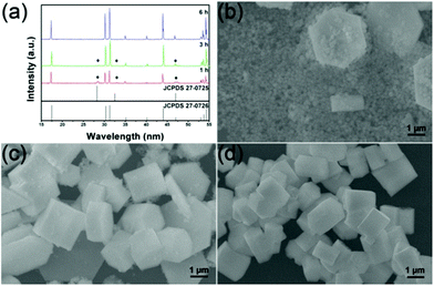 |
| | Fig. 6 XRD patterns (a) and FESEM images (b, c, d) of the β-NaLuF4 MCs synthesized with differing reaction times of 1 h, 3 h and 6 h, respectively. All of the samples were obtained with an EDA/EG volume ratio of 10:10 and NaNO3 content of 0.1 g. | |
Possible formation mechanism.
On the basis of the above analysis, it can be inferred that, besides the inherent unit cell structures of nucleated seeds, EG/EDA volume ratio, NaNO3 content in the initial solution, and reaction times are all important factors in the phase and morphology evolution of the final crystals. Scheme 1 summarizes the possible morphology formation processes of sodium lutetium fluoride under various experimental conditions.
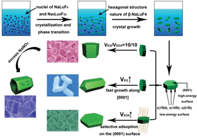 |
| | Scheme 1 Schematic illustration for the formation process of β-NaLuF4 MCs prepared under different conditions. | |
3.3. Luminescence properties of β-NaLuF4:Ln3+ (Ln = Eu, Tb, Ce/Tb)
Our experimental results and previous investigations reveal that β-NaLuF4 is a promising host lattice for doping optically active lanthanide ions.40,41 Accordingly, we mainly focus on comparison of the down-conversion (DC) luminescence properties of β-NaLuF4 MCs with different doping patterns of rare-earth ions, in an effort to show that our current solvothermal method is an efficient process for the synthesis of this kind of fluoride phosphor. All of the doping ratios of rare-earth ions are molar ratios in our experiments.
β-NaLuF4:2.5% Eu3+.
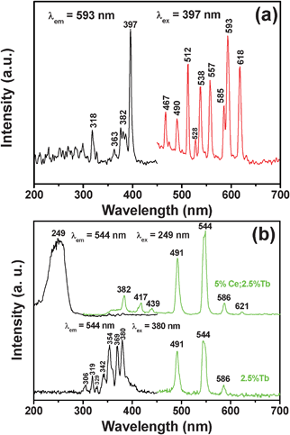
The excitation and emission spectra for the β-NaLuF4:2.5% Eu3+ sample are shown in Fig. 7a. The excitation (left) and emission (right) spectra of β-NaLuF4:2.5% Eu3+ shown in Fig. 7a are very similar to the previous report.41 The excitation spectrum (black line) consists of several characteristic excitation lines of Eu3+ within its 4f6 configuration from 200 to 450 nm, which can be clearly assigned (318 nm, 7F0 → 5H6; 363 nm, F0 → 5D4; 382 nm, 7F0 → 5G2; 397 nm, 7F0 → 5L6, strongest; 418 nm, 7F0 → 5D3), except for the weak ones at 255, 271, 289 and 301 nm (which contribute little to the excitation of Eu3+ and are of minor significance).59 This is different from the excitation spectra for Eu3+ in oxide hosts in which a charge-transfer band (CTB) of Eu3+–O2− is frequently observed between 200 and 300 nm. The CTB of Eu3+–F− (generally located below 200 nm) is not present in this region because of the much greater energy needed to remove an electron from F− than from O2−.60,61 Under excitation of the strongest 7F0 → 5L6 transition of Eu3+ at 397 nm, the corresponding emission spectrum (red line) of β-NaLuF4:2.5% Eu3+ comprises the emission lines associated with the Eu3+ transitions from the excited 5D0,1,2 levels to the 7FJ level, that is, 5D2 → 7F0 (467 nm), 5D2 → 7F2 (490 nm), 5D2 → 7F3 (512 nm), 5D1 → 7F1 (538 nm), 5D1 → 7F2 (557 nm), 5D0 → 7F1 (593 nm), 5D0 → 7F2 (618 nm).62–64 β-NaLuF4:2.5% Tb3+ and β-NaLuF4:5% Ce3+/2.5% Tb3+. The β-NaLuF4:2.5% Tb3+ and β-NaLuF4:5% Ce3+/2.5% Tb3+ samples emit a bright-green light under UV excitation. Fig. 7b shows the excitation (left) and emission (right) spectra of the samples. For β-NaLuF4:2.5% Tb3+, similarly to the Eu3+ complex, the excitation spectrum (black line in bottom of Fig. 7b) is composed of the characteristic f–f transition lines within the Tb3+ 4f8 configuration, which can be assigned to the transitions from the 7F6 ground state to the different excited states of Tb3+, that is, 288 nm (5I6), 306 nm (5H6), 321 nm (5D0), 344 nm (5G2), 356 nm (5D2), and 372 nm (5G6).65,66 Upon excitation into the 7F6 → 5D2 transition at 380 nm, the obtained emission spectrum consists of three obvious lines centered at 491, 544 and 586 nm, originating from the transitions from the 5D4 excited state to the 7FJ (J = 6, 5, 4) ground states of the Tb3+ ions, respectively (green line in bottom of Fig. 7b).67–69 And the 5D4 → 7F5 transition at 544 nm is the most intense group. Dramatically, when co-doping 5% Ce3+ with 2.5% Tb3+ into β-NaLuF4 MCs, dramatic changes took place in the excitation and emission spectra. Firstly, in the excitation spectrum, a broad absorption band at around 249 nm was observed (black line in top of Fig. 7b), instead of several absorption peaks in the excitation spectrum of β-NaLuF4:2.5% Tb3+. This indicates that the method of energy absorption has completely changed to the characteristic 4f–5d transition of Ce3+. Consequently, the corresponding emission spectrum has been strengthened obviously (green line in top of Fig. 7b). Additionally, the new emission peaks located at 382, 417, 439 and 621 nm appear, which are generated from the 4f–4f transition of the Tb3+ ion of 5D3 → 7F6, 5D3 → 7F5, 5D3 → 7F4, and 5D4 → 7F3, respectively. The proposed down-conversion mechanism in β-NaLuF4:Ce3+/Tb3+ MCs is demonstrated in Fig. 8.
 |
| | Fig. 7 Excitation (black lines) and emission spectra (red/green lines) of β-NaLuF4:2.5% Eu3+ (Fig. 7a), β-NaLuF4:2.5% Tb3+ (bottom of Fig. 7b) and β-NaLuF4:5% Ce3+/2.5% Tb3+ (top of Fig. 7b). | |
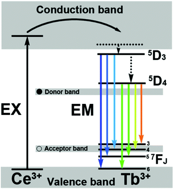 |
| | Fig. 8 The energy transfer mechanisms in β-NaLuF4:Ce3+/Tb3+ MCs. | |
In order to further investigate the luminescence properties of β-NaLuF4 MCs, samples with different Ce3+ doping concentrations were prepared by fixing the Tb3+ concentration at 2.5%. Fig. 9 shows the emission spectra of β-NaLuF4:Ce3+/Tb3+ with four Ce3+ concentrations of 2.5% Ce3+/2.5% Tb3+, 5% Ce3+/2.5% Tb3+, 7.5% Ce3+/2.5% Tb3+ and 10% Ce3+/2.5% Tb3+, respectively. It can be seen that the emission intensity increases with increasing Ce3+ concentration from 2.5% to 5%, and then decreases with further increase in Ce3+ concentration, which indicates that β-NaLuF4:5% Ce3+/2.5% Tb3+ MCs have the highest emission intensity. A possible interpretation is proposed as follows. When the Ce3+ concentration increases from 2.5% to 5%, more Ce ions become available to furnish and transfer the energy to the Tb3+, resulting in the higher emission intensity. When the Ce3+ concentration is further raised, the cross-relaxation process for the superfluous Ce3+ ions leads to the decrease in emission intensity. With the additional increase in Ce3+ concentration, the distance between neighbouring Ce3+ ions becomes shorter, which can enhance the interaction of the neighbouring Ce3+ ions and intensify the cross-relaxation process of Tb ions, thus resulting in concentration-dependent quenching.
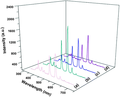 |
| | Fig. 9 Emission spectra of β-NaLuF4 MCs with doping concentrations of 2.5% Ce3+/2.5% Tb3+ (a), 5% Ce3+/2.5% Tb3+ (b), 7.5% Ce3+/2.5% Tb3+ (c), and 10% Ce3+/2.5% Tb3+ (d). | |
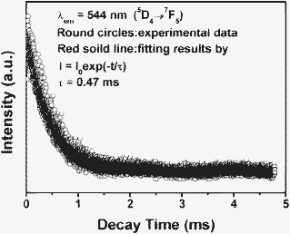 |
| | Fig. 10 Decay curve for the 5D4 → 7F5 emission of Tb3+ in β-NaLuF4:5% Ce3+/2.5% Tb3+. | |
The PL decay curve for the luminescence of β-NaLuF4:5% Ce3+/2.5% Tb is depicted in Fig. 10. This curve can be well fitted by a single exponential function as I(t) = I0 exp (−t/τ) (I0 is the initial emission intensity at t = 0, τ is the 1/e lifetime of the emission center), and the Tb3+ (5D4 → 7F5, detected at 544 nm) were determined to be 0.72 and 0.47 ms, respectively.
4. Conclusions
In summary, β-NaLuF4 MCs were synthesized through a mild and manageable solvothermal method by using EDA and EG as the mixed solvent and NaNO3 as the mineralizer. The results indicate that the solvent constitution has a significant role in the morphology, dimension and structure of the products. Besides, the dissolution–recrystallization process introduced by adding excess NaNO3 gives rise to a bigger size and micropore structure of the β-NaLuF4 MCs. Time-dependent experiments convincingly support the proposed analyses. The possible formation mechanisms for β-NaLuF4 MCs with diverse morphologies were presented in detail. Furthermore, co-doped Eu3+, Tb3+, and Ce3+ exhibit characteristic emission properties in the β-NaLuF4 MCs host, which bring effective improvement of the luminescence properties. Particularly, the DC luminescence properties of β-NaLuF4 can be obviously improved by co-doped Ce with Tb, which can be popularized to other NaREF4 materials. The products with peculiar characteristics may have the promising potential to serve as versatile luminescent phosphors in further applications.
Acknowledgements
Financially supported from Research Fund for the Doctoral Program of Higher Education of China (20112304110021), Harbin Sci.-Tech. Innovation Foundation (RC2012XK017012) and the Fundamental Research Funds for the Central Universities of China are greatly acknowledged.
References
- A. Umemura, S. Diring, S. Furukawa, H. Uehara, T. Tsuruoka and S. Kitagawa, J. Am. Chem. Soc., 2011, 133, 15506 CrossRef CAS.
- F.-R. Fan, Y. Ding, D.-Y. Liu, Z.-Q. Tian and Z. L. Wang, J. Am. Chem. Soc., 2009, 131, 12036 CrossRef CAS.
- Y. Xiong, H. Cai, B. J. Wiley, J. Wang, M. J. Kim and Y. Xia, J. Am. Chem. Soc., 2007, 129, 3665 CrossRef CAS.
- D. Tu, L. Liu, Q. Ju, Y. Liu, H. Zhu, R. Li and X. Chen, Angew. Chem., Int. Ed., 2011, 50, 6306 CrossRef CAS.
- Y. Dai, P. Ma, Z. Cheng, X. Kang, X. Zhang, Z. Hou, C. Li, D. Yang, X. Zhai and J. Lin, ACS Nano, 2012, 6, 3327 CrossRef CAS.
- D. Shi, H. S. Cho, Y. Chen, H. Xu, H. Gu, J. Lian, W. Wang, G. Liu, C. Huth, L. Wang, R. C. Ewing, S. Budko, G. M. Pauletti and Z. Dong, Adv. Mater., 2009, 21, 2170 CrossRef CAS.
- B. Lee, S. Lee, H. G. Jeong and K.-S. Sohn, ACS Comb. Sci., 2011, 13, 154 CrossRef CAS.
- W. B. Park, S. P. Singh, M. Pyo and K.-S. Sohn, J. Mater. Chem., 2011, 21, 5780 RSC.
- Z. Cai, X. Xing, R. Yu and X. Sun, Inorg. Chem., 2007, 46, 7423 CrossRef CAS.
- Y. Wang, Y. Liu, Q. Xiao, H. Zhu, R. Li and X. Chen, Nanoscale, 2011, 3, 3164 RSC.
- D.-P. Li, Z. Zheng, Y. Lei, F.-L. Yang, S.-X. Ge, Y.-D. Zhang, B.-J. Huang, Y.-H. Gao, K.-W. Wong and W.-M. Lau, Chem.–Eur. J., 2011, 17, 7694 CrossRef CAS.
- C. Zhang, C. Li, C. Peng, R. Chai, S. Huang, D. Yang, Z. Cheng and J. Lin, Chem. Eur. J., 2010, 16, 5672 CAS.
- P. Tonto, O. Mekasuwandumrong, S. Phatanasri, V. Pavarajarn and P. Praserthdam, Ceram. Int., 2008, 34, 57 CrossRef CAS.
- G. Li, C. Peng, C. Zhang, Z. Xu, M. Shang, D. Yang, X. Kang, W. Wang, C. Li, Z. Cheng and J. Lin, Inorg. Chem., 2010, 49, 10522 CrossRef CAS.
- B. Yang, P. R. F. Barnes, W. Bertram and V. Luca, J. Mater. Chem., 2007, 17, 2722 RSC.
- J. Ge and Y. Li, Adv. Funct. Mater., 2004, 14, 157 CrossRef CAS.
- Z. Wang, J. Hao and H. Chan, J. Mater. Chem., 2010, 20, 3178 RSC.
- X. Gou, F. Cheng, Y. Shi, L. Zhang, S. Peng, J. Chen and P. Shen, J. Am. Chem. Soc., 2006, 128, 7222 CrossRef CAS.
- Z. Li, J. Zeng and Y. Li, Small, 2007, 3, 438 CrossRef CAS.
- J. Hao, Y. Zhang and X. Wei, Angew. Chem., Int. Ed., 2011, 50, 6876 CrossRef CAS.
- N. Chouhan, C. L. Yeh, S.-F. Hu, R.-S. Liu, W.-S. Chang and K.-H. Chen, Chem. Commun., 2011, 47, 3493 RSC.
- Z. Liu, S. Peng, Q. Xie, Z. Hu, Y. Yang, S. Zhang and Y. Qian, Adv. Mater., 2003, 15, 936 CrossRef CAS.
- H. Yang, G. Liu, S. Qiao, C. Sun, Y. Jin, S. Smith, J. Zou, H. Cheng and G. Lu, J. Am. Chem. Soc., 2009, 131, 4078 CrossRef CAS.
- H. Wang, J. Robinson, X. Li and H. Dai, J. Am. Chem. Soc., 2009, 131, 9910 CrossRef CAS.
- W. Yin, J. Su, M. Cao, C. Ni, C. Hu and B. Wei, J. Phys. Chem. C, 2009, 114, 65 Search PubMed.
- L.-P. Zhu, H.-M. Xiao, W.-D. Zhang, G. Yang and S.-Y. Fu, Cryst. Growth Des., 2008, 8, 957 CAS.
- H.-S. Cho, Z. Dong, G. M. Pauletti, J. Zhang, H. Xu, H. Gu, L. Wang, R. C. Ewing, C. Huth, F. Wang and D. Shi, ACS Nano, 2010, 4, 5398 CrossRef CAS.
- X. Ye, J. E. Collins, Y. Kang, J. Chen, D. T. N. Chen, A. G. Yodh and C. B. Murray, Proc. Natl. Acad. Sci. U. S. A., 2010, 107, 22430 CrossRef CAS.
- F. Zhang, Y. Wan, Y. Shi, B. Tu and D. Zhao, Chem. Mater., 2008, 20, 3778 CrossRef CAS.
- Y. I. Park, J. H. Kim, K. T. Lee, K. S. Jeon, H. B. Na, J. H. Yu, H. M. Kim, N. Lee, S. H. Choi, S. I. Baik, H. Kim, S. P. Park, B. J. Park, Y. W. Kim, S. H. Lee, S. Y. Yoon, I. C. Song, W. K. Moon, Y. D. Suh and T. Hyeon, Adv. Mater., 2009, 21, 4467 CrossRef CAS.
- R.-S. Liu, Y.-H. Liu, N. C. Bagkar and S.-F. Hu, Appl. Phys. Lett., 2007, 91, 61119 CrossRef.
- S. R. Ghosh, T. F. Aeppli and G. Coppersmith, S. N., Nature, 2003, 425, 48 CrossRef CAS.
- T.-C. Liu, B.-M. Cheng, S.-F. Hu and R.-S. Liu, Chem. Mater., 2011, 23, 3698 CrossRef CAS.
- E. Downing, L. Hesselink, J. Ralston and R. Macfarlane, Science, 1996, 273, 1185 CAS.
- C. Lin and R.-S. Liu, J. Phys. Chem. Lett., 2011, 2, 1268 CrossRef CAS.
- G. Yi, H. Lu, S. Zhao, G. Yue, W. Yang, D. Chen and L. Guo, Nano Lett., 2004, 4, 2191 CrossRef CAS.
- L. Wang and Y. Li, Chem. Commun., 2006, 24, 2557 RSC.
- Z. Hou, C. Li, P. Ma, G. Li, Z. Cheng, C. Peng, D. Yang, P. Yang and J. Lin, Adv. Funct. Mater., 2011, 21, 2356 CrossRef CAS.
- F. Vetrone, R. Naccache, A. Zamarrón, A. Juarranz de la Fuente, F. Sanz-Rodríguez, L. Martinez Maestro, E. Martiín Rodriguez, D. Jaque, J. García Solí and J. A. Capobianco, ACS Nano, 2010, 4, 3254 CrossRef CAS.
- T. Chan, C. Dong, Y. Chen, Y. Lu, S. Wu, Y. Ma, C. Lin, R. Liu, J. Chen, J. Guo, J. Lee, H. Sheu, C. Yang and C. Chen, J. Mater. Chem., 2011, 21, 17119 RSC.
- C. Li, J. Yang, P. Yang, X. Zhang, H. Lian and J. Lin, Cryst. Growth Des., 2008, 8, 923 CAS.
- O. Guillot-Noël, B. Bellamy, B. Viana and D. Vivien, Phys. Rev. B: Condens. Matter, 1999, 60, 1668 CrossRef.
- J. A. Capobianco, F. Vetrone, J. C. Boyer, A. Speghini and M. Bettinelli, Opt. Mater., 2002, 19, 259 CrossRef CAS.
- D. Chen, Y. Wang and F. Weng, J. Phys. Chem. C, 2009, 113, 6406 CAS.
- M. Laroche, S. Girard, R. Moncorgé, M. Bettinelli, R. Abdulsabirov and V. Semashko, Opt. Mater., 2003, 22, 147 CrossRef CAS.
- F. Zhang, Y. Shi, X. Sun, D. Zhao and G. Stucky, Chem. Mater., 2009, 21, 5237 CrossRef CAS.
- D. Yang, X. Kang, M. Shang, G. Li, C. peng, C. Li and J. Lin, Nanoscale, 2011, 3, 2589 RSC.
- S. Nigam, V. Sudarsan, R. K. Vatsa, J. Ghattak and P. V. Satyam, J. Phys. Chem. C, 2009, 113, 8750 CAS.
- Y. Huang, H. You, G. Jia, Y. Song, Y. Zheng, M. Yang, K. Liu and N. Guo, J. Phys. Chem. C, 2010, 114, 18051 CAS.
- J.-W. Lee, J.-H. Lee, E.-J. Woo, H. Ahn, J.-S. Kim and C.-H. Lee, Ind. Eng. Chem. Res., 2008, 47, 5994 CrossRef CAS.
- S. Kar, C. Patel and S. Santra, J. Phys. Chem. C, 2009, 113, 4862 CAS.
- F. Lu, W. P. Cai and Y. G. Zhang, Adv. Funct. Mater., 2008, 18, 1047 CrossRef CAS.
- J. Jang, U. Joshi and J. S. Lee, J. Phys. Chem. C, 2007, 111, 13280 CAS.
- W. Liu, N. Wang, R. Wang, S. Kumar, G. Duesberg, H. Zhang and K. Sun, Nano Lett., 2011, 11, 2983 CrossRef CAS.
- X. Qu, H. Yang, G. Pan, J. W. Chung, B. Moon, B. Choi and J. H. Jeong, Inorg. Chem., 2011, 50, 3387 CrossRef CAS.
- R. Qin, H. Song, G. Pan, X. Bai, B. Dong, S. Xie, L. Liu, Q. Dai, X. Qu, X. Ren and H. Zhao, Cryst. Growth Des., 2009, 9, 1750 CAS.
- X. Hu, Y. Masuda, T. Ohji and K. Kato, Cryst. Growth Des., 2009, 10, 626 Search PubMed.
- G. Xi, K. Xiong, Q. Zhao, R. Zhang, H. Zhang and Y. Qian, Cryst. Growth Des., 2006, 6, 577 CAS.
- J. B. Liang, J. W. Liu, Q. Xie, S. Bai, W. C. Yu and Y. T. Qian, J. Phys. Chem. B, 2005, 109, 9436 Search PubMed.
- L. G. Deshazer and G. H. Dieke, J. Chem. Phys., 1963, 38, 2190 CrossRef CAS.
- J. C. Krupa and M. J. Queffelec, J. Alloys Compd., 1997, 250, 287 CrossRef CAS.
- M. Yu, J. Lin and J. Fang, Chem. Mater., 2005, 17, 1783 CrossRef CAS.
- Y. Liu, D. Tu, H. Zhu, R. Li, W. Luo and X. Chen, Adv. Mater., 2010, 22, 3266 CrossRef CAS.
- Y. Wang, Y. Liu, Q. Xiao, H. Zhu, R. Li and X. Chen, Nanoscale, 2011, 3, 3164 RSC.
- M. Yang, H. You, K. Liu, Y. Zheng, N. Guo and H. Zhang, Inorg. Chem., 2010, 49, 4996 CrossRef CAS.
- L. Yu, H. Song, Z. Liu, L. Yang and S. L. Z. Zheng, J. Phys. Chem. B, 2005, 109, 11450 CrossRef CAS.
- Z. Wang, Z. Quan, P. Jia, C. Lin, Y. Luo, Y. Chen, J. Fang, W. Zhou, C. O'Connor and J. Lin, Chem. Mater., 2006, 18, 2030 CrossRef CAS.
- Z. Wang, Z. Quan, J. Lin and J. Fang, J. Nanosci. Nanotech., 2005, 5, 1523 Search PubMed.
- C. Li and J. Lin, J. Mater. Chem., 2010, 20, 6831–6847 RSC.
|
| This journal is © The Royal Society of Chemistry 2012 |
Click here to see how this site uses Cookies. View our privacy policy here.