Cryogenically direct-plotted alginate scaffolds consisting of micro/nano-architecture for bone tissue regeneration
Hyeong
Jin Lee
and
Geun Hyung
Kim
*
Bio/Nanofluidics Laboratory, Department of Mechanical Engineering, Chosun University, Gwangju, 501-759, Korea. E-mail: gkim@chosun.ac.kr; Fax: +82-62-236-1534; Tel: +82-62-230-7180
First published on 24th July 2012
Abstract
Alginate, which can be derived from brown seaweed, is a well-known anionic linear polysaccharide. Alginate has been used extensively for tissue regeneration because it accelerates epithelialization and granular tissue formation, as well as encapsulating various growth factors due to its rapid gelation in calcium chloride. Although alginate is a good candidate as a natural tissue engineering material, difficulties in processing and its low mechanical properties as a porous structure remain important limitations. In previous work, we introduced multi-layered scaffolds using natural biomaterials, mainly collagen and chitosan, which were fabricated using a cryogenic direct-plotting process. The fabricated scaffolds showed good cellular activities; however, problems with regards to mechanical properties remained due to the presence of micropores. To overcome this limitation, we developed a new fabrication process that resulted in alginate scaffolds consisting of micropores in the shell and nanopores in the core region of a single strut. These alginate scaffolds exhibited good structural stability and a Young's modulus that was increased tenfold in the dry state in comparison to alginate scaffolds with a homogeneous micropore structure. The hierarchical scaffold showed highly viable cells in vitro, as well as sufficient alkaline phosphatase activity and calcium mineralization for bone tissue regeneration in comparison to a control alginate scaffold, which was fabricated using a conventional freeze-drying method. These results suggest that alginate scaffolds with a hierarchical structure have potential for use in hard tissue regeneration.
1. Introduction
Allografts and autografts are the current strategies for regenerating bone defects, but they have some shortcomings, which are limited availability and variable quality, hematoma, infection, increased operative time and bleeding, chronic donor site pain, and additional costs.1As another bone substitute, titanium and tantalum have been widely used as bone grafts, which are biocompatible, extremely corrosion resistant, and durable and non-biodegradable with a similar elastic modulus to that of the trabecular bone.1 Despite their favorable biological properties, bio-metals are intrinsically brittle and lack bio-degradability in biological conditions and have low processability. In particular, the high stiffness of titanium can lead to problems of stress-shielding and successive implant loosening.1 For these reasons, their clinical usage has been limited.1,2
Natural biopolymers, on the other hand, have some distinct advantages over bio-metals. Their biodegradation rates and mechanical properties can be controlled to a certain range for particular applications.2 In addition, they are easily fabricated into the desired 3D shape.3,4 For these reasons, biopolymers serve as a provisional skeleton because they gradually degrade and are replaced by new bone tissue.5 Alginate, one of the natural biopolymers, is biocompatible, hydrophilic, and biodegradable under physiological conditions.6 However, one of the major problems related with alginate is its low mechanical strength, which may limit its further application as templates for tissue regeneration and shape-controllability.2
Scaffolds are required in tissue engineering because their structures affect cellular activities.7–10 According to several researchers, two-dimensional (2D) scaffolds are unable to replicate the behaviour of cells in vivo.3 For this reason, spatially designed three-dimensional (3D) scaffolds that are structurally appropriate for 3D cell culture have been investigated. The main factors affecting cell seeding and nutrient and waste transport within the scaffold were pore size, pore shape, porosity, pore interconnectivity, tortuosity, and permeability.11–15 To develop an ideal 3D spatial scaffold, various optical, electrical, mechanical, and chemical methods have been used, such as freeze-drying, electrospinning, phase separation, gas forming, and solid-freeform fabrications (e.g., melt-plotting, printing, fused deposition modelling, stereolithography and laser sintering).16 In addition, several modified techniques (thermally induced phase-separation,17 direct laser writing (DLW),18–20 a polymer-leaching method,21 a cryogenic process combined with a freeze drying method,22,23 and electrohydrodynamic processes24,25) have been suggested. However, the original goal of these tools was to fabricate a pore-controlled structure with a high affinity for seeded cells. Cryogenic processes were used to fabricate 3D scaffolds with a controlled pore structure for various natural biopolymers.26,27 Our group used this technique to create multi-layered/pore size-controlled scaffolds using collagen, chitosan, and alginate.22,23,26,27 Although the optimum pore size and shape remain debated, cryogenically designed scaffolds with a stable pore size-controlled structure are an innovative biomaterial; they have the most uniform and controllable pore size and a completely interconnected pore structure. However, despite their dramatic pore-shape controllability and high porosity, the inadequate mechanical properties of such structures are insufficient to support tissue regeneration.
In this study, we propose a cryogenic design/freeze-drying and cross-linking process to control the internal structure of alginate struts, aimed at increasing the mechanical strength of 3D porous alginate scaffolds. Alginate, which is derived from brown seaweed, is a well-known anionic linear polysaccharide composed of 1,4-linked β-D-mannuronic (M) and α-L-guluronic acid (G) residues.28 It has been used extensively in tissue regeneration because it accelerates epithelialization and granular tissue formation, as well as encapsulating various growth factors due to its rapid gelation in calcium chloride.29,30 By cryogenically processing the alginate solution, we obtained 3D multi-layered alginate scaffolds that contained micro-sized alginate struts consisting of two internal pore structures (the core and shell region of struts). During the cross-linking process, a hybrid pore structure consisting of micro-sized (surface region) and nano-sized (core region) pores within the strut were generated due to the different diffusion rates of the various CaCl2 weight fractions. The layered alginate scaffolds exhibited over 90% porosity and completely interconnected pores, and showed highly improved mechanical properties as compared to scaffolds fabricated using the previous cryogenic process. To assess the capacity of the scaffolds to be used as biomaterials, various physical and biological activities, including water uptake ability, mechanical properties in the wet and dry states, viable cells, total protein content, and alkaline phosphatase (ALP) activity, were investigated, and an alizarin red Ca2+ quantization assay with osteoblast-like cells (MG63) was performed.
2. Results and discussion
2.1. Fabrication of alginate scaffolds with hybrid-structure
Using a cryogenic direct-plotting method we fabricated highly porous 3D alginate scaffolds, which are layer-by-layer structures. To obtain scaffolds, we designed the pore structure (pore size and shape and diameter of the alginate strut) using a computer aided design (CAD) system [Fig. 1(a)]. As a control material, we fabricated an alginate scaffold (C-scaffold) using a general freeze-drying method (10 wt% alginate) and cross-linked it with 5 wt% CaCl2 [Fig. 1(b)]. After designing the structure, the scaffold can be directly plotted using a 3-axis moving robot and a cryogenic cooling plate. The effect of moving speed and cryogenic temperature on the final struts was described previously.22,31Fig. 1(c) shows the cryogenically plotted alginate scaffold. Next, as shown in the schematic of Fig. 1(a), we performed two procedures to cross-link the alginate scaffolds. First, scaffolds were immediately placed in a freeze-dryer at −78 °C for three days [Fig. 1(d)]. The dried scaffold was then cross-linked in 5 wt% CaCl2 for 10 min at room temperature (RT) and again freeze-dried under the same conditions. We designated these ‘FC-alginate scaffolds’ [Fig. 1(e)]. Secondly, cryogenically plotted alginate struts were directly immersed in the same CaCl2 solution weight fraction at RT for 10 min [Fig. 1(f)]. The cross-linked scaffold was then freeze-dried as above. We designated these ‘CF-alginate scaffolds’ [Fig. 1(g)]. Fig. 1(e) and (g) show the final FC- and CF-scaffolds, respectively.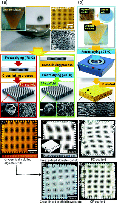 | ||
| Fig. 1 (a) A schematic of the cryogenic–freeze-drying process with two different procedures and (b) a schematic of the general freeze-drying process. (c) Cryogenically plotted alginate scaffolds at −20 °C. (d) Freeze-dried alginate scaffold, and (e) final FC-scaffold after cross-linking with 5 wt% CaCl2. (f) Cross-linked scaffold without freeze-drying and (g) dried final CF-scaffold. | ||
Fig. 2(a–c) show cross-sectional scanning electron microscope (SEM) images of the freeze-dried [Fig. 2(a)], FC- [Fig. 2(b)], and CF- [Fig. 2(c)] scaffolds. The FC-scaffold exhibited a highly rough surface, with struts of a slightly shrunken shape as compared to those of the cryogenically plotted alginate, while the struts of the CF-scaffolds were of a more stable shape.
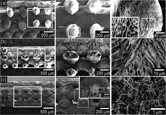 | ||
| Fig. 2 Cross-sectional SEM images of fabricated 3D alginate scaffolds. (a) SEM micrographs of a 3D alginate scaffold after freeze-drying. Cross-sectional SEM images of (b) FC- and (c) CF-scaffolds. In (c), the core region of the CF-scaffold shows a nano-sized pore structure, while in the shell region, micro-sized pores were observed. | ||
In a cross-sectional view of the CF-scaffold strut [Fig. 2(c)], two different pore structures can be seen, such as micro-sized pores in the shell region, similar to the cryogenically plotted struts [Fig. 2(a)]. However, nano-sized pores were found in the core region, while in the FC-scaffold, no hierarchical pore structure was evident. We believe that this was due to the different rates of CaCl2 absorption of the FC- and CF-scaffolds. In the case of the FC-scaffold, the completely porous structure of the strut can easily and quickly absorb the cross-linking agent, while the CF-scaffold cannot, since the iced region within the struts slows the wetting of the CaCl2 solution. This slowed absorption may cause the development of nano-sized pores in the core region due to melted iced alginate.
The effect of CaCl2 concentration on the absorption rate of CF-scaffolds was also characterized. Fig. 3(a) shows a schematic of the alginate cross-linking process for two different CaCl2 concentrations. We hypothesise two cross-linking mechanisms: at low CaCl2 concentrations, the frozen alginate strut is slowly cross-linked, such that iced alginate in the strut core region melts, while at high CaCl2 concentrations, the wetting rate into the strut is relatively high, such that the whole strut is rapidly cross-linked.
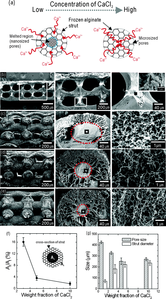 | ||
| Fig. 3 (a) A schematic of the effects of cross-linking agent concentration on nanopore and micropore development. Cross-sectional SEM images of the CF-scaffolds after treatment with (b) 1, (c) 3, (d) 5, and (e) 10 wt% CaCl2. (f) Region: An/At ratio. An and At represent the cross-sectional area of the nano-sized pores and the total cross-sectional area of the struts, respectively. (g) Pore size, which was defined as the distance between the alginate struts, and the strut diameter of the final alginate scaffolds. | ||
To evaluate the effect of CaCl2 concentration on nano-sized pores in the alginate struts, we fabricated several CF-scaffolds that were cross-linked using CaCl2 solutions of various weight fractions (1, 3, 5, and 10 wt%). Fig. 3(b–e) show cross-sectional SEM images of 3D alginate scaffolds cured using various CaCl2 weight fractions. Fig. 3(b) shows a CF-scaffold cross-linked using 1 wt% CaCl2. A multi-layered alginate structure was sustained; however, the struts were extremely shrunken and the micro-sized pores on the struts were completely removed due to the presence of solubilized alginate during the cross-linking process. These effects were abrogated with 3, 5, and 10 wt% CaCl2 weight fractions [Fig. 3(c–e)]. Compared to the image in Fig. 3(b), microporous structures on strut surfaces were present, but in the core area micropore-sized alginate had melted and nano-sized pores developed. However, increasing the concentration of the cross-linking agent lessened this phenomenon. In general, the process of cross-linking alginate can occur via two competing phenomena, i.e. the dissolution of alginate and desolubilization by the formation of cross-links between Ca2+ and alginate carboxyl groups.32 At low CaCl2 concentrations, alginate dissolution is dominant in the strut core-region, while at high CaCl2 concentrations, dissolution by the cross-linking process is completely blocked. Based on this reasoning, as the concentration of CaCl2 was increased, the melted region within the alginate struts was decreased. Furthermore, in the melted region, micro-sized structures can be reorganized into nano-sized pores [Fig. 3(e)]. In Fig. 3(f), At and An are the total cross-sectional area and the area of the nanopore structures in the struts, respectively.
Detailed pore and strut sizes of the fabricated alginate scaffolds, which were cross-linked with various CaCl2 weight fractions, are shown in Fig. 3(g). The pore sizes and strut diameters of the CF-scaffolds remained constant above 5 wt% of CaCl2. For this reason, we used 5 wt% CaCl2 as the cross-linking agent to compare the physical and biological properties of the FC- and CF-scaffolds.
Fig. 4 shows Fourier transform infrared spectroscopy (FTIR) spectra before and after cross-linking. The FTIR spectra exhibited alginate carboxyl peaks near 1631 cm−1, which represent symmetric COO− stretching vibrations, and near 1419 cm−1, which represent asymmetric COO− stretching vibrations. According to Mohan and Nair,33 when alginate is cross-linked with CaCl2, the symmetric COO− stretching vibration peak can be slightly shifted because of the ionic cross-linking of the COOH groups. We observed that the COO− peak was altered slightly from 1631 to 1587 cm−1. In addition, although the surface-pore structure of the CF-scaffolds cross-linked with 1 wt% CaCl2 was completely dissolved, the remaining structure was well cross-linked.
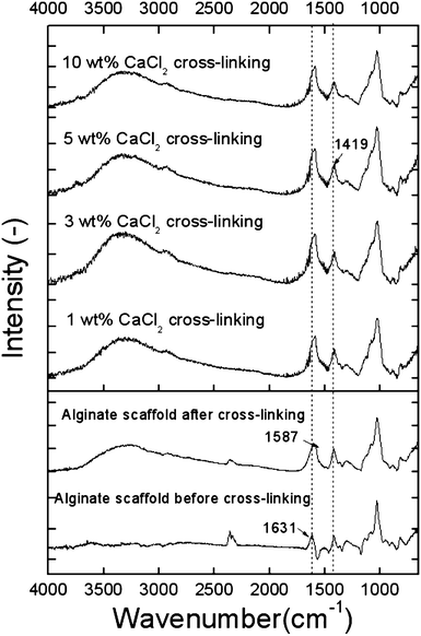 | ||
| Fig. 4 Infrared (IR) spectra of the alginate scaffolds cross-linked with various cross-linking agents (1, 3, 5, and 10 wt%). Lower graph: IR data showing alginate scaffolds before and after treatment with 5 wt% CaCl2. | ||
2.2. Mechanical properties of the scaffolds
The mechanical properties of the scaffolds are important, since implanted scaffolds can be subjected to various environmental stresses. In general, various spongy-shaped scaffolds, which are fabricated using natural biopolymers (e.g., collagen, chitosan, and alginate), are widely used because of their favourable biological properties. However, their inadequate mechanical properties remain an important limitation to their usage.34 To overcome this, our group suggested a core–shell design scaffold, in which the inner area contained alginate material and the outer area was extruded with collagen. As a result of this alginate area, the scaffold showed superior mechanical properties as compared with pure collagen scaffolds, along with similar biological activities. The method is highly innovative; however, the fabrication of a scaffold with adequate mechanical properties that is composed of a single material remains problematic.In this work, our target was to regenerate trabecular bone, which has a modulus from 38 to 130 MPa.35 The modulus is highly dependent on applied forces due to the anisotropic nature of the bone. To observe the mechanical properties of the FC- and CF-scaffolds, uniaxial tensile measurements were performed. Fig. 5(a) and (b) show the stress–strain curves for the dry and wet state conditions.
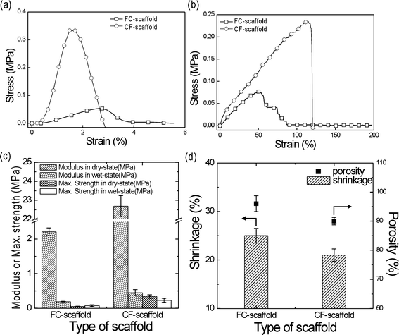 | ||
| Fig. 5 Stress–strain curves of the FC- and CF-alginate scaffolds in the (a) dry and (b) wet states. (c) The Young's modulus and maximum strength of the scaffolds. (d) The shrinkage and porosity of the FC- and CF-scaffolds. | ||
As shown in Fig. 5(a) and (b), the maximum tensile strength and modulus of the CF-scaffold dramatically increased compared to the FC-alginate scaffold. Table 1 provides a summary of the tensile properties under the same test conditions (ambient temperature = 28 °C and stretching speed = 2 mm s−1). As shown in Fig. 5(c), most of the mechanical properties were higher in the CF-scaffold as compared with the FC-scaffold. In particular, the Young's modulus of the CF-scaffold in the dry state was around tenfold greater (2.5 in the wet state) than the FC-scaffold [Fig. 5(c)]. We hypothesise that this was due to the different pore structure of the scaffolds. In general, the mechanical properties of the structured scaffolds are affected by pore structure, strut size, pore size, and porosity.36,37 In particular, porosity can markedly affect the mechanical properties. According to Ishai and Cohen,38 porosity can be related to the elastic modulus as follows,
| E(ϕ) = Eo(1 − ϕ2/3) |
| Young's modulus (MPa) | Maximum tensile strength (MPa) | |||
|---|---|---|---|---|
| FC-scaffold | CF-scaffold | FC-scaffold | CF-scaffold | |
| Dry state | 2.21 ± 0.11 | 22.69 ± 0.56 | 0.07 ± 0.02 | 0.33 ± 0.03 |
| Wet state | 0.19 ± 0.01 | 0.45 ± 0.09 | 0.07 ± 0.03 | 0.23 ± 0.02 |
The mechanical properties of the CF-scaffold may be sufficient for soft tissue regeneration, but remain low compared to the modulus of trabecular bone. However, the mechanical properties may be further improved through the use of a composite system supplemented with various bioceramics, such as beta-tricalcium phosphate or hydroxyapatite. In the near future, we will fabricate mechanically improved scaffolds composed of alginate and bioceramics.
Scaffold shrinkage (%) is described in Fig. 5(d). The CF-scaffold provided a more stable size change that was similar to our initial design concept.
2.3. Water uptake and retention and wetting properties
Water uptake ability is an important scaffold parameter for bone tissue regeneration because it reflects the ability to absorb physiological fluid and transfer nutrients and metabolites within the scaffold.34 In addition, a high water retention capacity can benefit practical applications, since a water-containing scaffold can sustain its shape during cell culture.40,41The FC-scaffold exhibited a higher water absorption and retention capacity than the CF-scaffold [Fig. 6(a)]. However, the differences were less than 10 and 15% for absorption and retention, respectively. Although the CF-scaffold showed a slightly lower water absorption and retention capacity, the absolute values of these properties indicate its ability to contain more than its own weight in water. Fig. 6(b and c) show the wetting behaviours of the FC- and CF-scaffolds. Water mixed with red dye (5 mL) was used to determine the absorption rate. Both the FC- and CF-scaffolds showed similarly high rates of wetting.
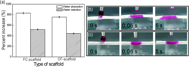 | ||
| Fig. 6 (a) Increased water absorption (%) and retention by FC- and CF-scaffolds, and optical images of the water wettability of the (b) FC-, and (c) CF-scaffolds vs. time. | ||
2.4. In vitro cell culture
To compare the bone tissue regeneration efficiency of the CF-scaffold with the FC-scaffold, we used osteoblast-like cells (MG63). Fig. 7(a) shows viable cells as determined by the MTT assay for the C-, FC-, and CF-scaffolds after one, three, and seven days of culture. Viable cells increased with time in all three scaffolds, and the control scaffold exhibited the highest attachment on day one. However, at seven days, viable cells on the FC- and CF-scaffolds were greater than that on the control scaffold. Thus, although initial attachment was relatively low due to the penetration of large pores and a high degree of pore-interconnections, the attached cells easily migrated and proliferated through the artificial pores to the thickest region of the scaffolds. In addition, the viable cells were slightly higher in the FC-scaffold. We believe that this was due to low initial attachment to the CF-scaffold due to lower water absorption as compared with the FC-scaffold.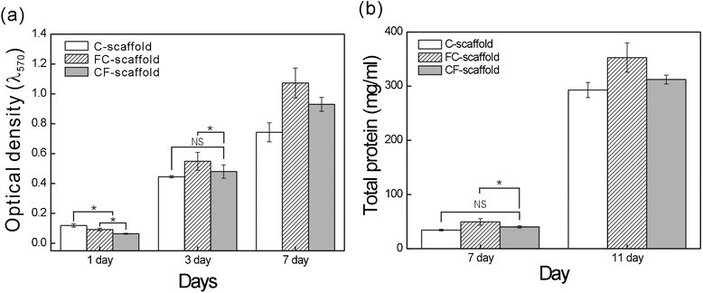 | ||
| Fig. 7 (a) MG63 viable cells after culture on the C-, FC-, and CF-scaffolds. (b) Total protein contents of the MG63 cells extracted from the alginate scaffolds over time. Asterisk (*) denotes P < 0.05; NS = not significant. | ||
The total protein content of the cells is shown in Fig. 7(b). There was a significant difference in the total protein content of the FC- and C- and CF-scaffolds. This trend was similar to the optical density of the viable cells at seven days, and we believe that the difference may depend on the area to which the cells can attach and proliferate.
Fig. 8(a) shows the ALP activity on the scaffolds, which is a marker of osteoblastic differentiation.42 The ALP activity was normalized to total protein content, and the value of the C-scaffold was set as 100%. The relative ALP levels of the proliferated cells on all the scaffolds were similar at seven days. However, activities on the FC- and CF-scaffolds at 11 days were markedly increased as compared with the C-scaffold. Although we are unable to explain this difference, it may be because the FC- and CF-scaffolds can provide a larger area for contact between the proliferating cells and the osteogenic factors in the culture media.
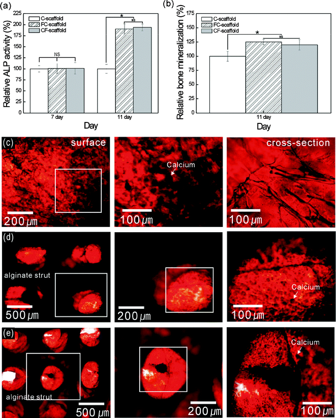 | ||
| Fig. 8 (a) The alkaline phosphatase activity of the MG63 cells on the alginate scaffolds from 7 to 11 days. (b) The calcium mineralization of the scaffolds at 11 days (n = 5). (c–e) ARS staining of the mineralization of the C-, FC-, and CF-scaffolds, respectively, on day 11. Asterisk (*) denotes P < 0.05. NS = not significant. | ||
Fig. 8(b) shows the calcium deposition on the scaffolds after 11 days, which was characterized using Alizarin Red dye and normalized to the total protein content. The calcium deposition showed a similar trend to the ALP activity. Calcium deposition on the FC- and CF-scaffolds was higher than that on the control scaffold. Fig. 8(c–e) shows the Alizarin Red calcium assay results for the C-, FC-, and CF-scaffolds at 11 days; more intense (similar to black) Alizarin Red-S staining indicates higher calcium concentrations. In both the FC- and CF-scaffolds, sufficient calcium mineralization was achieved, while in the C-scaffold calcium mineralization was evident at the surface, but not in the cross-sectional view, due to low cell migration or proliferation to the thickest portion of the C-scaffold.
3. Conclusions
Using a cryogenic process combined with freeze-drying and a novel cross-linking process, we fabricated 3D alginate scaffolds with a multi-layered pore structure and struts consisting of hierarchical pores. The hierarchical alginate scaffold (CF-scaffold) was used to improve the inadequate mechanical properties of the spongy alginate scaffold (FC-scaffold) for bone tissue regeneration. The CF-scaffolds consisted of micro-sized (shell) and nano-sized (core) pores, while the FC-scaffold showed homogeneous micro-sized pores. The extent of the nano-sized pore region was related to the cross-linking process and the cross-linking agent (CaCl2) weight fraction. Although the water absorption/retention capacity of the CF-scaffold was lower than that of the FC-scaffold, the improvement in mechanical properties was significant. In particular, the Young's modulus of the CF-scaffold in the dry state was tenfold higher than that of the FC-scaffold. The viable cells and the total protein content of the CF-scaffold in vitro was lower than that of the FC-scaffold, but the alkaline phosphatase activity and mineralization (Ca) levels were similar. These data suggest that by manipulating the internal structure of alginate, we can generate a mechanically improved and biologically sound multi-layered alginate scaffold. We also believe that this technique can be applied to drug delivery by accommodating various growth factors and peptides in the core region of the nano-sized pores, so that biologically functional scaffolds might be achieved.4. Experimental
4.1. Materials and fabrication methods
Intermediate-G sodium alginate was obtained from Sigma-Aldrich (St. Louis, MO, USA) and used for scaffold fabrication. Alginate solution was prepared at a fixed concentration of 10 wt% in phosphate buffered saline (PBS). Sodium alginate was melted in an autoclave at 120 °C for 10 min and cooled to RT. To understand the effect of the cross-linking agent on the hybrid pore structure (nanopore and micropore) within the struts, 1, 3, 5, and 10 wt% CaCl2 was used.This process has three setup procedures: (1) design of a pore structure-controlled and multi-layered scaffold under cryogenic conditions (−20 °C); (2) cross-linking of this scaffold in calcium chloride solution; and (3) freeze-drying. To fabricate multi-layered alginate scaffolds, we used a cryogenic process as described previously,22,23 combined with a 3-axis robot system (DTR3-2210-T-SG; DASA Robot, Bucheon, South Korea) and dispensing system (AD-3000C; Ugin-tech, Siheung, South Korea). The pore structure was controlled by manipulating system parameters, such as the nozzle moving speed, pneumatic pressure, and the temperature (−20 °C) of the cryogenic stage. Alginate struts were obtained using a 410 μm (inner diameter) and 710 μm (outer diameter) plotting nozzle, and the moving speed of the nozzle was set at 10 mm s−1 under pneumatic pressure (100 kPa) in an extrusion system. Alginate scaffolds were placed in a freeze-dryer (SFDSM06; Samwon, Busan, South Korea) at −78 °C for three days.
4.2. Characterization of the scaffolds
The pore structure of the alginate scaffolds was observed under an optical microscope (BX FM-32; Olympus, Tokyo, Japan) connected to a digital camera and a scanning electron microscope (SEM; Sirion, Hillsboro, OR, USA). All images were processed with Corel-draw (v. 9.0).Cross-linking of the alginate scaffolds was observed by Fourier transform infrared (FTIR) spectrometry (model 6700; Nicolet, West Point, PA, USA). The IR spectra represent the average of 30 scans between 500 and 4000 cm−1 at a resolution of 8 cm−1.
Water absorption ability was measured by weighing the scaffolds before and after soaking in distilled water for 2 h. The increase in water absorption was calculated as (%) = (W12h − Wo)/Wo × 100, where W12h is the weight of the scaffolds after 12 h and Wo is the original weight of the scaffold. To measure water retention, scaffolds immersed for 12 h were placed in a centrifuge tube that contained filter paper at the bottom, and then centrifuged at 500 rpm for 3 min and immediately weighed. The water retention percentage was calculated as (WR-12h − Wo)/Wo × 100, where WR-12h is the weight of the centrifuged scaffolds after 12 h.
To observe the wetting properties of the scaffolds, one droplet (5 μL) of water mixed with a red dye was carefully dropped on the surface of the scaffold, and water wetting images were captured with a digital camera.
The mechanical properties of the alginate scaffolds were evaluated by measuring the Young's modulus and maximum tensile strength.43–45 The tests were performed using scaffolds in ‘dry’ and ‘wet’ states. The specimens were cut into small strips (15 × 10 mm) and the mechanical properties of five samples were measured. The dry test was conducted in a dry state at RT. For the wetting test, the specimens were pre-wetted in PBS for 12 h and then measured in a wet state at 35 °C. Tensile strength was tested using a universal tensile machine (Top-tech 2000, Chemilab, Seoul, Korea). The stress–strain curves of the scaffolds were recorded at a stretching speed of 2 mm s−1.
The porosity of the scaffolds was obtained according to the equation,
| Porosity (%) = (1 − M/ρV) × 100 |
4.3. In vitro osteoblast-like cell (MG63) culture
Scaffolds (7 × 7 × 1.5 mm3) were sterilized with 70% EtOH and ultraviolet (UV) light, and placed in a culture medium overnight. Osteoblast-like cells (MG63; ATCC, Manassas, VA, USA) were used to observe the cellular behaviours in the scaffolds. MG63 cells were cultured in Dulbecco's modified Eagle's medium (DMEM; Hyclone, Logan, UT, USA) supplemented with 10% foetal bovine serum (FBS; Hyclone) and 1% penicillin–streptomycin (Hyclone). The cells were maintained up to passage eight and collected by trypsin–EDTA treatment. Approximately 50 μl of the culture medium containing 1 × 10⁵ cells was seeded on scaffolds in 24-well culture plates. The cells were allowed to attach to the scaffold for 4 h; 400 μl of fresh culture medium was then added to each well, and the cells were incubated in a 5% CO2 atmosphere at 37 °C. The medium was changed every other day. Viable cell numbers were determined by an MTT assay (Cell Proliferation Kit I; Boehringer Mannheim, Mannheim, Germany), based on the cleavage of the yellow tetrazolium salt 3-(4, 5-dimethylthiazolyl-2)-2,5-diphenyltetrazolium bromide (MTT). MTT is cleaved by mitochondrial dehydrogenases in viable cells to produce purple formazan crystals. Cells on the scaffold were incubated with 0.5 mg mL−1 MTT for 4 h at 37 °C, and the absorbance at 570 nm was measured using a microplate reader (EL800; Bio-Tek Instruments, Winnooski, VT, USA). Five samples were tested for each incubation period, and each test was performed in triplicate.4.4. Total protein content
Total protein content was measured using a bicinchoninic acid (BCA) protein assay (Pierce kit, Thermo scientific, USA). The cell-scaffold was assayed after culture for 7 and 11 days. The cell scaffold was washed with PBS and lysed with 1 mL triton X-100 (0.1%). An aliquot of the triton lysate (25 μL) was added to 200 μL of BCA working reagent and the mixture was incubated for 30 min at 37 °C. The protein concentration was determined from the absorbance at 562 nm by an enzyme-linked immunosorbent assay (ELISA) reader and converted to total protein concentration using a concentration curve.4.5. Alkaline phosphatase activity and Alizarin Red-S (ARS) staining
The alkaline phosphatase (ALP) activity of the MG63 cells seeded in the scaffolds for 7 and 11 days was assayed by measuring the release of p-nitrophenol from p-nitrophenyl phosphate (p-NPP). Scaffolds were rinsed gently with PBS and incubated in Tris buffer (10 mM, pH 7.5) containing 0.1% Triton X-100 for 10 min. This was followed by the addition of 100 μL of lysate to a 96-well tissue culture plate containing 100 μL of p-NPP solution, which was prepared using an ALP kit (Procedure No. ALP-10; Sigma-Aldrich). In the presence of ALP, p-NPP is transformed to p-nitrophenol and inorganic phosphate. The ALP activity was determined by measuring the absorbance at 405 nm using a microplate reader (Spectra III; SLT-Lab Instruments, Salzburg, Austria).Mineralization levels were determined by Alizarin Red-S staining in 24-well plates. MG63 cells were cultured in DMEM containing 50 μg mL−1 vitamin C and 10 mM β-glycerophosphate. The cells were then washed three times with PBS, fixed in 70% (v/v) cold ethanol (4 °C) for 1 h, and air-dried. Ethanol-fixed specimens were stained with 40 mM Alizarin Red-S (pH 4.2) for 1 h and washed three times with purified water. Specimens were then destained with 10% cetylpyridium chloride in 10 mM sodium phosphate buffer (pH 7.0) for 15 min. The optical density at 562 nm was measured using a Spectra III UV microplate reader. The ALP activity and calcium deposition were normalized to the total protein content.
4.6. Statistical analyses
All data presented are the means ± standard deviation (SD). Statistical analysis was assessed using SPSS (v.10.0). Statistical analyses consisted of single-factor analyses of variance (ANOVAs). The significance level was set at P < 0.05. NS denotes not-significant.Acknowledgements
This work was supported by the National Research Foundation of Korea grant funded by the Korea government (MEST) (grant no. 2012-0140), and also was supported by the Basic Science Research Program through the National Research Foundation of Korea funded by the Ministry of Education, Science, and Technology (grant no. 2011-0004097).References
- F. Matassi, L. Nistri, D. C. Paez and M. Innocenti, Clinical Cases in Mineral and Bone Metabolism, 2011, 8, 21 Search PubMed.
- X. Liu and P. X. Ma, Ann. Biomed. Eng., 2004, 32, 477 CrossRef.
- S. Yang, K. F. Leong, Z. Du and C. K. Chua, Tissue Eng., 2001, 7, 679 CrossRef CAS.
- L. E. Niklason, Nat. Biotechnol., 2000, 18, 929 CrossRef CAS.
- H. Petite, V. Viateau, W. Bensaid, A. Meunier, C. de Pollak, M. Bourguignon, K. Oudina, L. Sedel and G. Guillemin, Nat. Biotechnol., 2000, 18, 959 CrossRef CAS.
- T. A. Becker, D. R. Kipke and T. Brandon, J. Biomed. Mater. Res., 2001, 54, 76 CrossRef CAS.
- R. Langer and J. P. Vacanti, Science, 1993, 260, 920 CAS.
- P. X. Ma and J. W. Choi, Tissue Eng., 2001, 7, 23 CrossRef CAS.
- C. Ranucci, A. Kumar, S. P. Batra and P. V. Moghe, Biomaterials, 2000, 21, 783 CrossRef CAS.
- W. P. Daley, S. B. Peters and M. Larsen, J. Cell Sci., 2008, 121, 255 CrossRef CAS.
- J. D. Kretlow and A. G. Mikos, AIChE J., 2008, 54, 3048 CrossRef CAS.
- V. Karageorgiou and D. Kaplan, Biomaterials, 2005, 26, 5474 CrossRef CAS.
- S. M. Roosa, J. M. Kemppainen, E. N. Moffitt, P. H. Krebsbach and S. J. Hollister, J. Biomed. Mater. Res. Part A, 2009, 92, 359 Search PubMed.
- R. Landers, A. Pfister, U. Hubner, H. John, R. Schmelzeisen and R. Mulhaupt, J. Mater. Sci., 2002, 37, 3107 CrossRef CAS.
- L. Moroni, R. Schotel, D. Hammann, J. R. de Wijn and C. A. van Blitterswijk, Adv. Funct. Mater., 2008, 18, 53 CrossRef CAS.
- P. D. Dalton, T. Woodfield and D. W. Hutmacher, Biomaterials, 2009, 30, 701 CrossRef.
- H. Ma, J. Hu and P. X. Ma, Adv. Funct. Mater., 2010, 20, 2833 CrossRef CAS.
- A. Ovsianikov, S. Schlie, A. Ngezahayo, A. Haverich and B. Chichkov, J. Tissue Eng. Regener. Med., 2007, 1, 443 CrossRef CAS.
- P. Tayalia, C. R. Mendonca, T. Baldacchini, D. J. Mooney and E. Mazur, Adv. Mater., 2008, 20, 4494 CrossRef CAS.
- F. Klein, B. Richter, T. Striebel, C. M. Franz, G. V. Freymann, M. Wegener and M. Bastmeyer, Adv. Mater., 2011, 23, 1341 CrossRef CAS.
- S. W. Choi, J. Xie and Y. Xia, Adv. Mater., 2009, 21, 2997 CrossRef CAS.
- G. H. Kim, S. H. Ahn, H. Yoon, Y. Y. Kim and W. Chun, J. Mater. Chem., 2009, 19, 8817 RSC.
- G. H. Kim, S. H. Ahn, Y. Y. Kim, Y. Cho and W. Chun, J. Mater. Chem., 2011, 21, 6165 RSC.
- Z. Ahmad, M. Rasekh and M. Edirisinghe, Macromol. Mater. Eng., 2010, 295, 315 CrossRef CAS.
- G. H. Kim, S. H. Ahn, H. J. Lee, S. Y. Lee, Y. Cho and W. Chun, J. Mater. Chem., 2011, 21, 19138 RSC.
- S. H. Ahn, Y. H. Koh and G. H. Kim, J. Micromech. Microeng., 2010, 20, 65015 CrossRef.
- H. Lee and G. H. Kim, Carbohydr. Polym., 2011, 85, 817 CrossRef CAS.
- B. Balakrishnan and A. Jayakrishnan, Biomaterials, 2005, 26, 3941 CrossRef CAS.
- E. Alsberg, K. W. Anderson, A. Albeiruti, R. T. Franceschi and D. J. Mooney, J. Dent. Res., 2001, 80, 2025 CrossRef CAS.
- X. Li, T. Liu, K. Song, L. Yao, D. Ge and C. Bao, Biotechnol. Prog., 2006, 22, 1683 CAS.
- S. H. Ahn, H. Yoon, G. H. Kim, Y. Y. Kim, S. H. Lee and W. Chun, Tissue Eng., Part C, 2010, 16, 813 CrossRef CAS.
- A. E. Pavlath, C. Gossett, W. Camirand and G. H. Robertson, J. Food Sci., 1999, 64, 61 CrossRef CAS.
- N. Mohan and P. D. Nair, Trends Biomater., Artif. Organs, 2005, 18, 219 Search PubMed.
- S. J. Hollister, Nat. Mater., 2005, 4, 518 CrossRef CAS.
- J. L. Williams and J. L. Lewis, J. Biomech. Eng., 1982, 104, 50 CrossRef CAS.
- T. M. Freyman, I. V. Yannas and L. J. Gibson, Prog. Mater. Sci., 2001, 46, 273 CrossRef CAS.
- G. H. Kim and J. G. Son, Appl. Phys. A: Mater. Sci. Process., 2009, 94, 781 CrossRef CAS.
- O. Ishai and L. J. Cohen, Int. J. Mech. Sci., 1967, 9, 539 CrossRef.
- A. Bignon, J. Chouteau, J. Chevalier, G. Fantozzi, J. P. Carret, P. Chavassieux, G. Boivin, M. Melin and D. Hartmann, J. Mater. Sci.: Mater. Med., 2003, 14, 1089 CrossRef CAS.
- H. Liu, J. Mao, K. Yao, G. Yang, L. Cui and Y. Cao, J. Biomater. Sci., Polym. Ed., 2004, 15, 25 CrossRef CAS.
- W. W. Thein-Han and R. D. K. Misra, Acta Biomater., 2009, 5, 1182 CrossRef CAS.
- Y. Gotoh, K. Hiraiwa and M. Narajama, Bone Miner., 1990, 8, 239 CrossRef CAS.
- M. G. Yeo and G. H. Kim, Chem. Mater., 2012, 24, 903 CrossRef CAS.
- H. Lee, S-H. Ahn and G. H. Kim, Chem. Mater., 2012, 24, 881 CrossRef CAS.
- M. G. Yeo, W-K. Jung and G. H. Kim, J. Mater. Chem., 2012, 22, 3568 RSC.
| This journal is © The Royal Society of Chemistry 2012 |
