Layer-by-layer deposition and photovoltaic property of Ru-based metal–organic frameworks†
Deok Yeon Leea,
Eun-Kyung Kima,
Chan Yong Shina,
Dipak V. Shindea,
Wonjoo Leeb,
Nabeen K. Shrestha*a,
Joong Kee Leec and
Sung-Hwan Han*a
aDepartment of Chemistry, Hanyang University, Seoul 133-791, Republic of Korea. E-mail: shhan@hanyang.ac.kr; nabeenkshrestha@hotmail.com; Fax: +82-2-2299-0762; Tel: +82-2-2220-0934
bDepartment of Defense Ammunitions, Daeduk College, Daejeon 305-715, Republic of Korea
cKorea Institute of Science and Technology, Seoul 136-791, Republic of Korea
First published on 13th February 2014
Abstract
In the present work, thin films of ruthenium based metal–organic frameworks are synthesized using a layer-by-layer (LbL) technique and the film is characterized using XRD, FE-SEM, UV/visible spectroscopy, cyclic voltammetry and photoluminance spectroscopy. Further, the feasibility of the MOF film as a sensitizer in a solar cell is investigated. The HOMO–LUMO level of the frameworks is estimated and is found to be suitable to allow the use of the frameworks as a sensitizer for TiO2. When TiO2 mesoporous film is sensitized with the LBL thin film of the frameworks and a Grätzel type liquid junction solar cell is constructed, it demonstrates the cell performance of Isc = 2.56 mA cm−2, Voc = 0.63 V, FF = 0.63, and Eff = 1.22%. Photoluminescence spectroscopy and electrochemical impedance spectroscopy show that iodine doping into the frameworks is essential to facilitate the photogenerated electron transfer from the frameworks to TiO2.
1. Introduction
Metal–organic-frameworks (MOFs) are highly porous crystalline materials formed by coordination of metal ions with organic ligands.1–6 Owing to their topologically diverse and extraordinarily high areal porous surface with tunable pore size, adjustable surface functionalization, and their capacity of storing various guest molecules, MOFs are gaining great attention.7–12 As MOFs can also be derived from edible natural products, application of such biofriendly frameworks can have more advantages in biomedicals, for example as a carrier in drug or gene delivery or in delivery of various active molecules needed for diagnosis and treatment.13–16 Beyond host–guest chemistry, recently MOFs have also been investigated in catalysis17–19 and electrochemical devices.20–22 Apart from their porous topological application, MOFs have also been investigated as chemical sensors23 and photocatalysts.24–28 Recently, the concepts of MOFs based solar cell are emerging and some reports on application of MOFs as potentially active materials in photovoltaics can also be found.29–37 However, a fully devised solar cell based on MOFs as active material for harvesting solar energy has been rarely investigated. Very recently, it has been demonstrated that thin film of MOFs can be used as a sensitizer to harvest solar radiations in a TiO2 based liquid junction solar cell, which exhibited Jsc of 1.25 mA cm−2, Voc of 0.49 V, fill factor of 0.43 and power conversion efficiency of 0.26%.38 The power conversion efficiency of the cell was further enhanced to 0.46% by addition of carbon nanotubes.39 Although the efficiency is lower than the current state of art of the similar devices, there are lots of future possibilities to improve the performance of the MOF based solar cell. As large variety of metal ions and organic ligands are available, the combinations of the two components can generates endless possibilities with the hybrid properties resulting from sum of the properties of the metal ions and the organic linkers. Hence, some of their combinations can create MOFs with a suitable electronic and optical properties required for harvesting solar radiations effectively in solar cells. As most of the ruthenium compounds are photoactive and ruthenium based MOFs exhibits visible light driven photocatalysis,27 it is noteworthy to investigate the feasibility of Ru-based MOFs as sensitizer in a solar cell. Herein, a thin film of ruthenium based MOFs is synthesized in the present work using a layer-by-layer (LBL) technique and the layer is investigated as a sensitizer in a TiO2 based liquid junction solar cell.2. Experimental methods
Synthesis of bulk powder MOFs
As a reference material, bulk powder of Ru-MOFs with the structure analogous to HKUST-1 and with mix valent Ru (RuII, RuIII) in the frameworks was synthesized solvothermally as described previously.40 In brief, the following molar ratios of the mixture 3RuCl3·xH2O–2H3btc (i.e., 1,3,5-benzenetricarboxylate)–5CH3COOH–925H2O was reacted at 160 °C in a Teflon-lined autoclave for 72 h. After synthesis, the dark green-grey precipitates (MOFs) were collected and carefully washed several times with water and absolute ethanol. After drying the product under argon at room temperature, calcination of the material was conducted at 100 °C under vacuum for 2 h.Preparation of MOF film by LbL method
Thin film of MOFs was fabricated by dipping an amine functionalized glass slide in to a Ru-metal ion solution consisting of 10 mM RuCl3 in 10 mM CH3COOH aqueous solution for 1 h followed by dipping the glass slide again for 1 h in an organic ligand solution consisting of 10 mM H3btc in 10 mM CH3COOH aqueous solution. This successive dipping of the substrate in metal ion and ligand solution is defined as one LBL cycle. Both the solutions were maintained at about 120 °C and in between switching the substrate from one solution to another, it was washed to remove the unadsorbed reactant molecules by dipping the substrate in the solvent. Several LbL cycles were performed to obtain optimum thickness of the MOF film. MOFs film was characterized using XRD (X-ray diffractometer, D/MAX RINT 2000), UV/visible spectroscopy (CARY 100 Conc UV-visible spectrophotometer), FE-SEM (field emission scanning electron microscopy, S-4800, Hitachi), CV (cyclic voltammetry, BAS-100B/W electrochemical workstation).Preparation of hole blocking layer (HBL)
A very thin film (∼60 nm) of TiO2 HBL was coated on a FTO glass by spreading few drops of 0.15 M titanium-diisopropoxide bis(acetylacetonate) in 1-butanol and spinning at 2000 rpm for 30 s. The spin coated sample was annealed at 500 °C for 20 min.Sensitization of TiO2 film with MOFs and cell fabrication
As a photoanode for a solar cell, about 17 μm thick mesoporous film of TiO2 was prepared on a HBL coated FTO glass by doctor blade method using a commercially available TiO2 nanoparticle paste and the film was sintered at 450 °C for 30 min. The TiO2 film was sensitized by dipping it into the above mentioned Ru-metal ion and organic ligand solutions for several LbL cycles. After sensitization, the photoanode was dipped in 0.1 M I2 solution prepared in acetonitrile for 8 h (beyond 8 h no further capturing of iodine was observed) in order to dope MOFs with iodine. The photoanode was characterized using UV/visible spectroscopy, FE-SEM, and PL (photoluminescence spectroscopy, photon counting spectrofluorimeter-PC1, ISS). A sandwich type Grätzel cell was constructed using a polyimide tape as a spacer and a Pt coated FTO glass (Pt was coated by spreading few drops of 7 mM H2PtCl4·6H2O prepared in 2-propanol on the FTO surface followed by sintering at 400 °C for 20 min) as a counter electrode. By injecting I3−/I− redox electrolyte (Iodolyte AN-50, Solaronix, Switzerland) into the cell, current–voltage (I–V) curves were recorded using a computer-controlled digital source meter (Keithley 2400) under illumination of an active area of 0.25 cm2. The illumination was carried out using a solar simulator (PEC-L01, Peccell) under the condition of 100 mW cm−2 (1 sun, 1.5 AM). The cell was further characterized by measuring incident photon to current conversion efficiency (K3100 spectral IPCE measurement system, McScience) and EIS (electrochemical impedance spectroscopy, IVIUM, COMPACTSAT.e).3. Results and discussion
Characterization of MOFs and MOF sensitized films
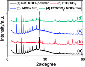
Fig. 1 shows the XRD patterns of the bulk MOF powder (i.e., reference MOFs) and LbL thin film MOFs on a glass substrate. The reference bulk MOFs have exactly the similar XRD patterns as reported previously.40 Similarly, the XRD patterns of the LbL thin film of MOFs are also matching with the reference bulk MOFs sample particularly at 2θ < 20 degree, which are the characteristic XRD signals of MOF materials. This finding suggests that the bulk powder MOFs and the LBL thin film MOFs are of the same materials. After confirming the successful preparation of thin film MOFs by LbL technique, exactly the same recipe and the procedures were applied in order to sensitize TiO2 mesoporous film. The XRD patterns of TiO2 mesoporous film before and after depositing MOFs are also shown in Fig. 1. After deposition of MOFs, the TiO2 film shows some additional XRD signals, especially at 2θ < 20 degree, which are well matching with the reference bulk MOFs and LbL thin film of MOFs (Fig. 1). The surface and cross sectional morphology of the LBL film is shown in Fig. S1 (ESI†), which shows that the film is consisted of densely agglomerated MOF nanoparticles (Fig. S1a†) and the film has an uniform thickness of about 180 nm for 10 LBL cycles (Fig. S1b†). The UV/visible absorption spectrum of the LBL film shows an absorption peak at ∼535 nm (Fig. S1c†), which can be ascribed to the characteristic absorption peak due to d–d transition in ruthenium metal ion of the frameworks. Fig. S2a and b (ESI†) show the top surface morphology of the TiO2 mesoporous film before and after deposition of MOFs by LbL method. The corresponding cross-sectional SEM views of the TiO2 film before and after deposition of MOFs are shown in Fig. 2a and b. From the cross-sectional images, it can be clearly realized the penetration of reactants from the deposition bath throughout the TiO2 film – most importantly up to the bottom of the film and thereby deposition of MOFs. In contrast to the TiO2 film, the MOFs loaded TiO2 film in UV/visible spectrum (Fig. 3) exhibits the absorption of visible light, which is one of the primary criteria of a material to be used as sensitizer in light harvesting devices. The UV/visible spectrum of the MOFs loaded film also shows a broad hump at around 530 nm to 540 nm. As suggested by the characteristic electronic absorption peak of ruthenium ion in Fig. S1b (ESI†), the absorption hump in Fig. 3 is supposed to be due to d–d transition of ruthenium ion in the frameworks.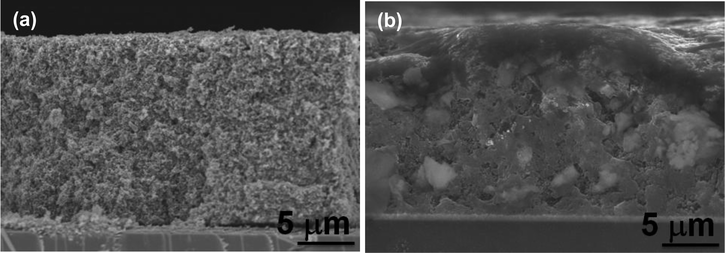 | ||
| Fig. 2 SEM cross-sectional views of doctor blade TiO2 film on FTO glass (a) before and (b) after, deposition of Ru-MOFs for 10 LbL cycles. | ||
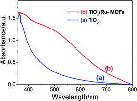 | ||
| Fig. 3 UV/visible spectrum of doctor blade TiO2 film on FTO glass (a) before and (b) after, deposition of Ru-MOFs for 10 LbL cycles. | ||
Energy level of MOFs and charge transfer phenomenon
Apart from the visible light absorption characteristic, the MOFs under study must possess suitable HOMO and LUMO positions relative to the conduction band of TiO2 (−4.2 eV vs. vacuum). Using the electronic absorption data, the HOMO–LUMO energy gap of the MOFs is estimated to be 2.26 eV (Fig. S3a, ESI†) and from the onset of oxidation peak in CV38,41 (Fig. S3b, ESI†), the HOMO level of the MOFs is estimated to be −5.47 eV vs. vacuum. From these data, the LUMO level of the MOFs is calculated as −3.21 eV vs. vacuum. The estimated LUMO level of the MOFs is higher than the conduction band of TiO2, which is desirable for the MOFs to be used as a sensitizer. When such MOFs sensitized TiO2 film is exposed to the solar radiations, electron excitation undergoes from HOMO to LUMO level of the MOFs. As in the dye sensitized solar cell, the excited electrons from LUMO level of the MOFs should transfer to the conduction band of TiO2 before recombination of charge carriers takes place. In order to investigate the charge transfer from MOFs to TiO2, PL spectroscopy of the MOFs sensitized TiO2 film was studied and the results are shown in Fig. 4. However, Fig. 4 shows a very intense PL emission suggesting no charge transfer or possibly due to very slow transfer and thereby assisting the recombination. Based on the previous work,38,39,42–44 molecular doping of iodine into the MOFs was carried out in order to enhance the electronic conductivity of the frameworks and thereby to facilitate the charge transfer process. The iodine doping of the frameworks is confirmed by immersing the LBL film of MOFs into the 0.1 M iodine solution in acetonitrile for a long time enough to capture iodine sufficiently and measuring the change in concentration of the iodine solution with time (Fig. S4, ESI†). After iodine doping, the MOFs sensitized TiO2 film shows the quenching of PL emission quantitatively (Fig. 4). This finding suggests the charge transfer process from the LUMO level of the iodine doped frameworks into the conduction band of TiO2. The charge transfer after iodine doping is due to the interactions between iodine and π-electron from the aromatic ring of ligands, which can result in cooperative electron transfer, (metal to ligand charge transfer: MLCT), and hence facilitates the electron transfer from the frameworks to TiO2.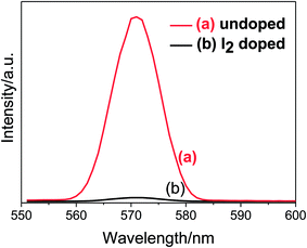 | ||
| Fig. 4 Emission spectrum of TiO2/Ru-MOFs film (a) before and (b) after, doping MOFs with iodine. Excitation at wavelength = 535 nm. | ||
Characterization of photovoltaic cells
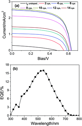
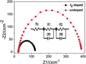
Appropriate assembling of sensitizer with TiO2 is necessary (generally, large areal coverage is preferred) to obtain higher power conversion efficiency. Therefore, TiO2 film was sensitized with LbL film of MOFs and the photovoltaic performance of the cell was measured after iodine doping at various LBL cycles. Fig. 5a shows the I–V curves of the cell at various stages of LBL cycles and the detail photovoltaic parameters measured are tabulated in Table S1 (ESI†). Thus, these data demonstrate the best cell performance at 10 LBL cycles. At this condition, the cell exhibits Isc = 2.56 mA cm−2, Voc = 0.63 V, fill factor = 0.63, and power conversion efficiency (Eff) = 1.22%. As expected, the photocurrent and the power conversion efficiency of the present work are higher (2.05 times and 4.7 times, respectively) than the previously reported work on Cu-based MOFs sensitized solar cell.38 In addition, to the best of our knowledge this is the first report on such higher performance of MOFs sensitized solar cell. Although the conversion efficiency of the present work is still lower compared to dye sensitized solar cell, there are lots of possibilities to further enhance the performance of the MOF sensitizer. For example, by choosing a suitable ligand which can increase the conductivity of the frameworks and narrow down the energy gap between the LUMO level of frameworks and the conductance band of TiO2, charge transfer process can be performed more effectively. On the other hand, as large number of metal ions and organic ligand are available, there are lots of future possibilities. It should be noticed in Fig. 5a and Table S1† that with increasing the LBL cycles, the photocurrent is also increasing accordingly due to the gradual increase of the MOFs loading into the TiO2 film. This result also supports that the MOFs under study are acting as a sensitizer. In addition, IPCE measurement of the cell was performed, which shows the maximum efficiency of ∼16% at about 535 nm of the incident light (Fig. 5b). The maximum conversion efficiency is demonstrated at the incident light where the maximum absorbance takes place (see Fig. 5b and S1b†). This finding further supports that the MOFs are acting as a sensitizer in the present work. It is very noteworthy to notice in Fig. 5a that the TiO2 film sensitized with undoped MOFs demonstrated a very poor cell performance. In order to understand the role of iodine doping, the cell was further investigated using EIS and the raw data were fitted using the equivalent circuit shown in inset of Fig. 6. In the circuit, Rs denotes the resistance of the electrolyte and the FTO substrate or equivalent series resistance. R1 and R2 are the charge transfer resistance (Rct) of the interfaces of the counter electrode/electrolyte and porous electrode (TiO2-MOFs)/electrolyte, respectively. The Nyquist plots of the cell under open circuit and 1 sun illumination conditions are shown in Fig. 6 and the quantitatively fitted results based on the equivalent circuit is tabulated in Table S2 (ESI†). From the plots, R2 values for iodine doped and undoped cases are found to be 129.26 and 364.08 Ω cm2, respectively. This result suggests that the iodine doping reduces the charge transfer resistance and thereby facilitates the charge transfer process from MOFs to TiO2.4. Conclusions
The present work demonstrates that ruthenium based MOFs can work as a sensitizer to harvest solar radiation in photovoltaic devices. However, iodine doping is essential in order to facilitate charge transfer from the LUMO level of the frameworks to the conduction band of TiO2. The cell demonstrated much higher performance than the previously reported Cu-based MOF sensitized solar cell. Although the efficiency of the MOFs sensitized cell is still lower than the current state of the art in this type of devices, finding a suitable ligand, which can introduce intrinsic conductivity of the frameworks and narrow down the energy gap between the LUMO level of the frameworks and the conduction band of TiO2, could further enhance the power conversion efficiency. On the other hand, a large number of metal ions and a variety of organic linkers are available. Therefore, an infinite number of combinations are possible to make MOFs with different electronic and light harvesting properties, which can further improve the power conversion efficiencies.Acknowledgements
This research was supported by the Basic Science Research Program through the National Research Foundation of Korea (NRF) funded by the Ministry of Education (2013009768) and by the KIST Institutional Program (2E23964). One of the authors (N. K. Shrestha) is supported by The Korean Federation of Science and Technology Societies under Brain Pool program.References
- B. F. Hoskins and R. Robson, J. Am. Chem. Soc., 1990, 112, 1546–1554 CrossRef CAS
.
- H. Li, M. Eddaoudi, M. O'Keeffe and O. M. Yaghi, Nature, 1999, 402, 276–279 CrossRef CAS PubMed
.
- S. Kitagawa, R. Kitaura and S. Noro, Angew. Chem., Int. Ed., 2004, 43, 2334–2375 CrossRef CAS PubMed
.
- G. Férey, Chem. Soc. Rev., 2008, 37, 191–214 RSC
.
- J.-P. Zhang, Y.-B. Zhang, J.-B. Lin and X.-M. Chen, Chem. Rev., 2012, 112, 1001–1033 CrossRef CAS PubMed
.
- A. D. Naik, M. M. Dîrtu, A. P. Railliet, J. Marchand-Brynaert and Y. Garcia, Polymers, 2011, 3, 1750–1775 CrossRef CAS
.
- H. Chae, D. Y. Siberio-Perez, J. Kim, Y. Go, M. Eddaoudi, A. Matzger, M. O'Keeffe and O. M. Yaghi, Nature, 2004, 427, 523–527 CrossRef CAS PubMed
.
- M. J. Rosseinsky, Microporous Mesoporous Mater., 2004, 73, 15–30 CrossRef CAS PubMed
.
- X. Zhao, B. Xiao, A. J. Fletcher, K. M. Thomas, D. Barshaw, M. J. Rosseinsky, X. Zhao, B. Xiao, A. J. Fletcher, K. M. Thomas, D. Barshaw and M. J. Rosseinsky, Science, 2004, 306, 1012–1015 CrossRef CAS PubMed
.
- D. G. Samsonenko, H. Kim, Y. Sun, G.-H. Kim, H.-S. Lee and K. Kim, Chem. – Asian J., 2007, 2, 484–488 CrossRef CAS PubMed
.
- R. B. Getman, Y.-S. Bae, C. E. Wilmer and R. Q. Snurr, Chem. Rev., 2012, 112, 703–723 CrossRef CAS PubMed
.
- K. Sumida, D. L. Rogow, J. A. Mason, T. M. McDonald, E. D. Bloch, Z. R. Herm, T.-H. Bae and J. R. Long, Chem. Rev., 2012, 112, 724–781 CrossRef CAS PubMed
.
- R. A. Smaldone, R. S. Forgan, H. Furukawa, J. J. Gassensmith, A. M. Z. Slawin, O. M. Yaghi and J. F. Stoddart, Angew. Chem., Int. Ed., 2010, 49, 8630–8634 CrossRef CAS PubMed
.
- A. C. McKinlay, R. E. Morris, P. Horcajada, G. Ferey, R. Gref and S. C. Couvreur, Angew. Chem., Int. Ed., 2010, 49, 6260–6266 CrossRef CAS PubMed
.
- S. Keskin and S. Kizilel, Ind. Eng. Chem. Res., 2011, 50, 1799–1812 CrossRef CAS
.
- P. Horcajada, R. Gref, T. Baati, P. K. Allan, G. Maurin, P. Couvreur, G. Férey, R. E. Morris and C. Serre, Chem. Rev., 2012, 112, 1232–1268 CrossRef CAS PubMed
.
- V. I. Isaeva and L. M. Kustov, Pet. Chem., 2010, 50, 167–180 CrossRef
.
- J. Y. Lee, O. K. Farha, J. Roberts, K. A. Scheidt, S. T. Nguyen and J. T. Hupp, Chem. Soc. Rev., 2009, 38, 1450–1459 RSC
.
- B. Li, Y. Zhang, D. Ma, L. Li, G. Li, G. Li, Z. Shi and S. Feng, Chem. Commun., 2012, 48, 6151–6153 RSC
.
- R. Díaz, M. G. Orcajo, J. A. Botas, G. Calleja and G. Palma, Mater. Lett., 2012, 68, 126–128 CrossRef PubMed
.
- D. Y. Lee, S. J. Yoon, N. K. Shrestha, S.-H. Lee, H. Ahn and S.-H. Han, Microporous Mesoporous Mater., 2012, 153, 163–165 CrossRef CAS PubMed
.
- D. Y. Lee, D. V. Shinde, E.-K. Kim, W. Lee, I.-W. Oh, N. K. Shrestha, J. K. Lee and S.-H. Han, Microporous Mesoporous Mater., 2013, 171, 53–57 CrossRef CAS PubMed
.
- L. E. Kreno, K. Leong, O. K. Farha, M. Allendorf, R. P. Van Duyne and J. T. Hupp, Chem. Rev., 2012, 112, 1105–1125 CrossRef CAS PubMed
.
- J.-L. Wang, C. Wang and W. Lin, ACS Catal., 2012, 2, 2630–2640 CrossRef CAS
.
- L. Wen, J. Zhao, K. Lv, Y. Wu, K. Deng, X. Leng and D. Li, Cryst. Growth Des., 2012, 12, 1603–1612 CAS
.
- C. Wang, Z. Xie, K. E. DeKrafft and W. Lin, J. Am. Chem. Soc., 2011, 133, 13445–13454 CrossRef CAS PubMed
.
- Y. Kataoka, K. Sato, Y. Miyazaki, K. Masuda, H. Tanaka, S. Naito and W. Mori, Energy Environ. Sci., 2009, 2, 397–400 CAS
.
- Y. Horiuchi, T. Toyao, M. Saito, K. Mochizuki, M. Iwata, H. Higashimura, M. Anpo and M. Matsuoka, J. Phys. Chem. C, 2012, 116, 20848–20853 CAS
.
- C. G. Silva, A. Corma and H. García, J. Mater. Chem., 2010, 20, 3141–3156 RSC
.
- J. I. Feldblyum, E. A. Keenan, A. J. Matzger and S. Maldonado, J. Phys. Chem. C, 2012, 116, 3112–3121 CAS
.
- J. T. Joyce, F. R. Laffr and C. Silien, J. Phys. Chem. C, 2013, 117, 12502–12509 CAS
.
- W.-W. Zhan, Q. Kuang, J.-Z. Zhou, X.-J. Kong, Z.-X. Xie and L.-S. Zheng, J. Am. Chem. Soc., 2013, 135, 1926–1933 CrossRef CAS PubMed
.
- C. A. Kent, B. P. Mehl, L. Ma, J. M. Papanikolas, T. J. Meyer and W. Lin, J. Am. Chem. Soc., 2010, 132, 12767–12769 CrossRef CAS PubMed
.
- Y. Li, A. Pang, C. Wang and M. Wei, J. Mater. Chem., 2011, 21, 17259–17264 RSC
.
- J. I. Feldblyum, E. A. Keenan, A. J. Matzger and S. Maldonado, J. Phys. Chem. C, 2012, 116, 3112–3121 CAS
.
- C. Kent, D. Liu, A. Ito, T. Zhang, B. Mehl, J. Papanikolas, T. Meyer and W. Lin, Preprint ACS Energy and Fuels, 2012, 57, 654–655 CAS
.
- H. A. Lopez, A. Dhakshinamoorthy, B. Ferrer, P. Atienzar, M. Alvaro and H. Garcia, J. Phys. Chem. C, 2011, 115, 22200–22206 CAS
.
- D. Y. Lee, D. V. Shinde, S. J. Yoon, K. N. Cho, W. Lee, N. K. Shrestha and S.-H. Han, J. Phys. Chem. C DOI:10.1021/jp4079663
.
- D. Y. Lee, C. Y. Shin, S. J. Yoon, H. Y. Lee, W. Lee, N. K. Shrestha, J. K. Lee and S.-H. Han, Sci. Rep., 2014, 4(3930), 1–5, DOI:10.1038/srep03930
.
- O. Kozachuk, K. Yusenko, H. Noei, Y. Wang, S. Walleck, T. Glaser and R. A. Fischer, Chem. Commun., 2011, 47, 8509–8511 RSC
.
- Y. Chen, M. E. EI-Khouly, M. Sasaki, Y. Araki and O. Ito, Org. Lett., 2005, 7, 1613–1616 CrossRef CAS PubMed
.
- Y. Kobayashi, B. Jacobs, M. D. Allendorf and J. R. Long, Chem. Mater., 2010, 22, 4120–4122 CrossRef CAS
.
- M.-H. Zeng, Q.-X. Wang, Y.-X. Tan, H.-X. Hu, S. Zhao, L.-S. Long and M. Kurmoo, J. Am. Chem. Soc., 2010, 132, 2561–2563 CrossRef CAS PubMed
.
- C. H. Hendon, D. Tiana and A. Walsh, Phys. Chem. Chem. Phys., 2012, 14, 13120–13132 RSC
.
Footnote |
| † Electronic supplementary information (ESI) available. See DOI: 10.1039/c4ra00397g |
| This journal is © The Royal Society of Chemistry 2014 |

