
 Open Access Article
 This Open Access Article is licensed under a
 Creative Commons Attribution 3.0 Unported Licence
Reversely toposelective vapor deposition at normal pressure and temperature by capillary condensation†‡
Ville A.
Lovikka
 *,
Marianna
Kemell
,
Marko
Vehkamäki
and
Markku
Leskelä
*,
Marianna
Kemell
,
Marko
Vehkamäki
and
Markku
Leskelä
Department of Chemistry, University of Helsinki, A.I. Virtasen Aukio 1, P.O. Box 55, FI-00014 Helsinki, Finland. E-mail: ville.lovikka@helsinki.fi
First published on 11th March 2019
Abstract
Modern technology is heavily dependent on a family of vapor deposition methods where thin coatings are formed by introducing gaseous reagents on solid substrates. However, a major drawback in these methods is the difficulty in miniaturizing them to complex nanoscaled structures. Based on capillary condensation, the curvature/capillary selective vapor deposition method is able to coat nanostructures selectively starting from the previously hardest-to-reach surfaces, ledges, interstices, and pores, while leaving the external surfaces in or near their native state. This method requires no pumping, purification or purging, heating or expensive apparatus, and the presence of small amounts of oxygen was shown to improve the process. Finally, studying the fundamentals of the proposed method is hypothesized to create a foundation for a novel vapor deposition paradigm for toposelective coating methods in nano- and micron-scale structures.
Conceptual insightsCapillary/curvature selective vapor deposition (CSVD) presents a vapor deposition (VD) method which is able to coat or fill surfaces that have been previously hardest-to-reach in virtually all VD techniques. Because CSVD utilizes capillary condensation, this method targets primarily cracks, narrow interstices, ledges, and even ink-bottle-shaped nanopores. This method presents also an easy way to control the selectivity process down to the nanoscale without pretreating the substrate. The discourse in the existing literature is focused on making VD coatings as conformal on surfaces as possible, and if the process fails, as it usually does to some degree, the results are assumed to be subconformal. Our work shows that superconformal coatings are not only possible but desirable, and that the superconformality can be controlled up to the point where the VD process becomes surface selective. Additionally, because CSVD reverses or bypasses several issues known in many VD methods, such as sensitivity to gas phase impurities or a need for pumping, we argue that our research lays the groundwork for an entirely new VD paradigm. Because the process is very simple, it is easy to apply even by newcomers with a cheap and simple self-made reactor, as instructed in the manuscript. |
1. Introduction
Chemical vapor deposition (CVD) and physical vapor deposition (PVD) are a family of vapor deposition (VD) methods which are a crucial cornerstone for modern technology and human society.1–3 Unfortunately, VD methods have scaling limitations on the nanoscale: the coating may grow thicker on external rather than internal surfaces. The narrower the structures, the stronger is the limiting effect up to a point where all the pore mouths become blocked and nanofeatures planarized, while surfaces out of line-of-sight may even be left untouched. The most controllable method thus far, atomic layer deposition (ALD),4 is able to coat high aspect ratio nanostructures, yet the method can only coat conformally at best and is therefore incapable of filling ink-bottle shaped pores and many other complex features. Instead, we hypothesize that non-conformal coating could be accomplished consistently based on the inherent physical properties of substrates. One such property is surface curvature, which gives rise to capillary condensation (CC). CC is a phenomenon of gas-to-liquid condensation below the saturation point of the condensate, and it scales negatively with feature size. In other words, the smaller the substrate surface features or the smaller the surface curvature, the larger the deviation from saturation allowed for CC to occur.5 Therefore CC is prevalent in structures which are typically the hardest to reach with traditional VD methods, for example in the smallest pores and the tightest corners, inside cracks and interstices, and beneath ledges. In theory, this “inside out” selectivity is reverse in comparison to typical VD techniques, and therefore utilizing CC could be an extremely potent novel tool in nanotechnology. In this manuscript, curvature/capillary selective vapor deposition (CSVD) is proposed and studied with various substrates. Implications of the findings and how they may help in shaping a new VD paradigm are briefly discussed.2. Theory
In confined spaces, i.e. capillaries, the liquid phase is stable below the saturation point of a liquid, a phenomenon known as capillary condensation (CC). The smaller the confinement is, the larger the deviation of the adsorbate partial pressure (pM) from the saturation pressure (psat) may be to maintain a liquid phase. CC is mostly a physical phenomenon, so it is universal on all adsorbates and surfaces as long as the surface is at least partially wetting under the given conditions.5 In principle, coated areas could be selected by simply controlling the saturation ratio (SR = pM/psat), which defines the feature sizes, capillary widths and surface curvatures where the liquid phase is stable.Initiated CVD (iCVD)6,7 and its variant, photoinitiated CVD (piCVD),8 are submethods of polymeric CVD where a monomer and an initiator are introduced in the reaction chamber and polymerization is started by a thermal or radiative activation.9 Typical reactor conditions do not allow reagent equilibration on the surfaces because the species react on the substrate surfaces before any phase equilibrium has time to set in. The monomer has a smaller likelihood to end up on harder-to-reach surfaces, such as nanopores, than on external surfaces, before being fixed by a chemical reaction. This selectivity can be reversed by utilizing CC and delaying initiation until thermodynamic equilibrium has been reached. This decoupling allows independent optimization of the mass transfer and allocation from the adsorbate fixation. Even without equilibrium, partial selectivity has been shown when the initiation power was set low enough10 or delayed.11 However, these observations were not properly utilized, developed, or explained but instead factors such as lower film viscosity, film flow, and “liquid-like” properties were suggested.
The CSVD method shares many advantages with (p)iCVD over solution phase methods. Because a carrier gas is used instead of a solvent, solvent-related detrimental effects on the deposition process or the substrate are avoided. The deposited film requires no cleaning, or drying, and even physiologically safe materials are readily produced. The monomer is distilled during the evaporation–condensation process; hence, there is no need to purify it before the reaction. With gaseous reagents there are no immiscibility problems. In addition, the process conditions are very mild, which allows modification of virtually any surface.6,12 Photoinitiated CVD has additional benefits of good energy efficiency, independence from heating, and easy applicability of masks for surface patterning.8 CC limited coatings could have additional benefits. CC is possible even in a closed reactor where adsorbates would be added in predefined amounts and then allowed to equilibrate with surfaces through the vapor phase. Due to utilizing equilibrium, in theory, fluid flow dynamics inside the reactor should not affect the coating thicknesses or conformality, the process can operate at normal pressure, and the reagent consumption can be minimized. Therefore the CSVD method could save multiple processing steps and tremendous effort, making it industrially feasible, and even allow depositions which have been impossible before.
There are known complicating factors that are especially relevant for CSVD. CVD polymerization may accelerate once the newly formed polymer film starts increasing the monomer adsorption on the surface.13 This behavior suggests that various parameters, including the length of initiation and all the factors governing mass transfer near the substrate surface, could affect how quickly a polymer film would overgrow. In addition, there is an array of confinement effects that affect the kinetics of acrylate polymerization situationally, by either accelerating14 or decelerating15 it. There are also substrate surface specific chemical and physical factors, such as the monomer contact angle with the surface, which changes the meniscus shape and alters the corresponding equilibrium pressures.5 Weak enough interaction between the substrate and the monomer may also lead to metastable states, reducing reproducibility,16 and contaminants may facilitate capillary condensation by stabilizing the liquid phase.17 Because some of these factors vary strongly according to the substrate and reactor design, there may not be a universal rule for size-selective pore filling. Instead, it is very possible that each reactor–substrate–adsorbate system needs to be studied and optimized separately as concluded in polymer physics research inside anodized aluminum oxide (AAO) pores.18
3. Materials and methods
3.1. Reactor
A simple and low-cost reactor was built (ca. €1500, Fig. 1). The reactor line allowed stepless control over the monomer saturation ratio (SR) inside the reaction chamber with two rotameters (Kytola Instruments Oy, Finland). The setup included a carrier gas bypass, which served as the purge line for both the monomer feed line and the reaction chamber. The body of the reactor line consisted of 6 mm Teflon tubing, ball valves, 3-way connectors, and 3-way valves (Helsinki Valve & Fitting Oy, Finland). A glassy 3-way stopcock (Lenz Laborglas GmbH, Germany) was used as a 3-way connector after the bubbling bottle, because it allowed connection of the three tubes in any combination. The bubbler was a gas washing bottle with a porous glass fingertip. The reaction chamber was a 1′′ wide quartz tube, which was connected to the inlet and exhaust by lab-welded 1/6′′ to 1′′ stainless steel adapters and 1/6′′ and 1′′ ultra-Torr fittings (Helsinki Valve & Fitting Oy) with viton o-rings, for easy and repeatable opening. The glass bubbling bottle was connected to 6 mm Teflon tubing with self-made rubber–parafilm seals. The connections with the glassy 3-way valve were sealed with parafilm. The reactor line was slightly overpressurized, which prevented convective leakages into the reactor line. The UV lamp was a low pressure Hg lamp with a major emission line at 254 nm. | ||
| Fig. 1 The experimental reactor line setup. | ||
3.2. Curvature selective vapor deposition by condensate equilibration
The reactor chamber was kept at normal pressure while 99.999% N2 (Oy AGA Ab, Finland) was bubbled through ethyl acrylate (EA, >99%, TCI), tert-butyl methacrylate (t-BMA, >98%, TCI) or styrene (>99%, Sigma-Aldrich) monomer, chosen due to their good volatility, relatively low toxicity and good self-initiating properties under UV irradiation known for many acrylates19 and styrene.20 The washing bottle was placed in a water bath at 35–40 °C. The draft inside the fumehood was aimed between the bubbler and the reactor (arrow in Fig. 1), which caused condensation of the monomer in the tubing upon which the monomer–carrier gas feed was considered to be saturated by the monomer. The final SR of the monomer was adjusted before the reactor by mixing the saturated feed with a clean carrier gas in a predefined ratio. The gas flow was stopped before starting UV-exposure. After the exposure, the reactor was purged briefly with N2 before opening the reactor and storing the samples in air. The SR-values between 18 and 96% were used. The initiation times were 3–15 minutes. The carrier gas was bubbled through the monomer at a maximum rate of 30 ml min−1 for at least 1 hour. In some experiments, synthetic air (20% O2 in N2, Oy Aga Ab, Finland) was mixed in the carrier gas for up to 2–3% O2 content unless otherwise noted.When conducting this experiment, caution is recommended, as some acrylates might undergo a very violent self-accelerating polymerization at elevated temperatures. Depending on the monomer storage history, temperatures above ca. 40 °C should be considered risky. In addition, using pure nitrogen as the carrier gas deoxygenates the monomer which incapacitates its storage inhibitor.21–23
3.3. Substrates
Glass was obtained by shattering a Fisherbrand pasteur pipette (Thermo Fisher Scientific, USA) and using the internal concave surface for the experiments, FESEM imaging, and EDS analysis. The substrate was scratched with a diamond pen in order to produce nanoparticles on the surface. Anodized aluminum oxide (AAO) substrates on Al substrates (InRedox, USA) were used as obtained. The samples were scratched before the polymerization experiments in order to create cracks, particles, and bends with various surface curvatures on the surface. Ni nanorod substrates were prepared by template-directed electrodeposition in porous alumina membranes (Whatman Anodisc, membrane diameter 13 mm, thickness 60 μm, pore diameter 0.2 μm) using a procedure described in ref. 24.3.4. Field emission SEM and energy dispersive X-ray spectrometry (EDS)
The samples were placed on carbon tape and sputtered with a 1.5–5 nm layer of Au/Pd before imaging with a Hitachi S-4800 FESEM. The EDS spectra were measured at 5 keV using an Oxford INCA 350 energy dispersive X-ray spectrometer connected with the Hitachi FESEM. The amounts of polymer at different locations were estimated by comparing the carbon Kα and silicon Kα X-ray signals.3.5. Focused Ion Beam SEM (FIB-SEM)
An FEI Quanta 3D 200i FIB-SEM was used for preparation of cross-sectional areas for electron microscopy. For the glass specimens, periodic introduction of trimethyl(methylcyclopentadienyl)platinum(IV) gas was necessary during gallium ion milling to mitigate specimen charging at the cross-sectional sites. Prior to FIB-SEM work, a surface grounding layer was needed on the entire specimen. This was done by sputter deposition of a 20 nm Au/Pd metal coating. The cross-sections were imaged with either the Quanta FIB-SEM or Hitachi FESEM.4. Results
Polymeric menisci were formed in different capillaries and curved surfaces based on the applied saturation ratio, initiation time, and oxygen content. The results could be repeated systematically; however, the selectivity could not be fully controlled on anodized aluminum oxide. Substrate-specific observations are presented further below. Polymer was grown also on the reactor walls with long initiation times and high SRs, especially when no oxygen was present, possibly lowering the initiation efficiency on the substrate surfaces. The results are for the ethyl acrylate monomer unless otherwise stated.4.1. Ni-Nanopillars and the saturation ratio (SR)
The amount and location of polymeric coating depended on the applied SR. SEM images (Fig. 2) showed clear shifts in how polymeric coating proceeded from interstitial spaces towards more open surfaces. The sizes of menisci were larger and smaller curvatures were needed to promote polymeric coating when the SR was high. An initiation time of 5 minutes was applied unless otherwise noted.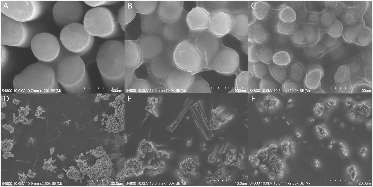 | ||
| Fig. 2 FESEM micrographs of Ni-nanopillar substrates after CSVD at various SRs. (A–C) Gradual filling of nanopillar interstices at 51%, 86% and 96%, respectively. (D–F) Gradual meniscus expansion and filling between nanopillar regions at 72%, 81% and 86%, respectively. | ||
At 19% SR, the texture of the substrate surface was distinguishable and no capillaric filling could be identified unambiguously. At 51% SR, the capillaric bridges between the nanopillars reached approximately 100 nm in width and were easily spotted in SEM (Fig. 2A). Although the capillaric bridges continued to grow at larger SRs, the nanopillar bundles and their interspaces still appeared empty at 72% SR (D). At 81% SR, the bundles were filled but their outside edges seemed to remain uncovered (E). The polymer started to grow outside the bundles only if there was another bundle within ∼1 μm distance. At 86% SR (8 min initiation), the nanopillar bundles were filled, although the polymer was seen retracting under e-beam irradiation (B). Up to ∼3 μm wide capillaric bridges also appeared between neighboring bundles and the floor features were less visible. Large menisci started to grow from the corner between the floor and the pillars, which gradually covered the outside edges of the nanopillar bundles (F). At 96% SR, the polymeric coating was thicker than those of the previous samples, covering everything except for some of the nanopillar extremities (C). The polymer menisci were at their thickest around the nanopillars and they leveled off only after several microns away from the nanopillar bundles. The substrate surface could only occasionally be seen through the meniscus bottom (Fig. S1, ESI‡).
A cross-sectional SEM micrograph (Fig. S2A, ESI‡) revealed perfect polymeric filling inside a nanopillar bundle even in interstitial locations where the space had very challenging geometries. The peaks of the tallest nanopillars had no observable coating.
4.2. Glass, the effect of initiation length and oxygen
Glass surfaces were covered with nano- and micron-sized particles, which were fixed in place by polymeric menisci. Meniscus sizes varied according to particle size and shape, SR, and the length of initiation. Initiation for 3 minutes caused observable polymerization, but usually 5–8 minutes was applied to ensure proper polymerization and to increase the coating stability under electron beam irradiation. At 8 minutes, >95% SR caused micron wide menisci (Fig. 3A), which were reduced in size to hundreds and tens of nanometers at 50% (B) and 18% (C) SR, respectively. No extensive thickening of menisci was observed off the particles; however, it could not be concluded whether barely observable, darker areas outside actual menisci were a sign of the commencing (p)iCVD type of growth (Fig. 3A and C). In cross-sectional imaging polymeric growth was observed only in narrow gaps between two surfaces (Fig. S2B, ESI‡). By increasing the initiation time to 15 minutes, a (p)iCVD process factor became obvious, as can be seen in Fig. 3D–F, where thicker and less selective growth is more abundant. At 95% SR, particles were covered by an overgrowing polymeric layer and more “droplets” could be seen without any observed seeding particle (D). The meniscus growth was smaller at 50% (E), and at 18% SR the menisci were limited even further in size. At higher magnifications tiny droplet-like formations could still be found on open surfaces (F); however, significant amounts of carbon were not detected outside menisci with EDS analysis (Fig. 3I and Fig. S3, ESI‡). Adding oxygen to the carrier gas (G and H) made the process more CSVD type by reducing meniscus size and overgrowth around particles at a high SR (G, 95% SR), and also by reducing unattributed growth (H, 18% SR). However, a large number of either small particles or starting points for polymerization were still observed on open surfaces (Fig. 3H) and sometimes in the meniscus (Fig. S4, ESI‡). When the oxygen content was increased by an order of magnitude, polymeric menisci were still formed but they occasionally appeared even more irregular with particle-like internal structures (20% O2, Fig. S4, ESI‡).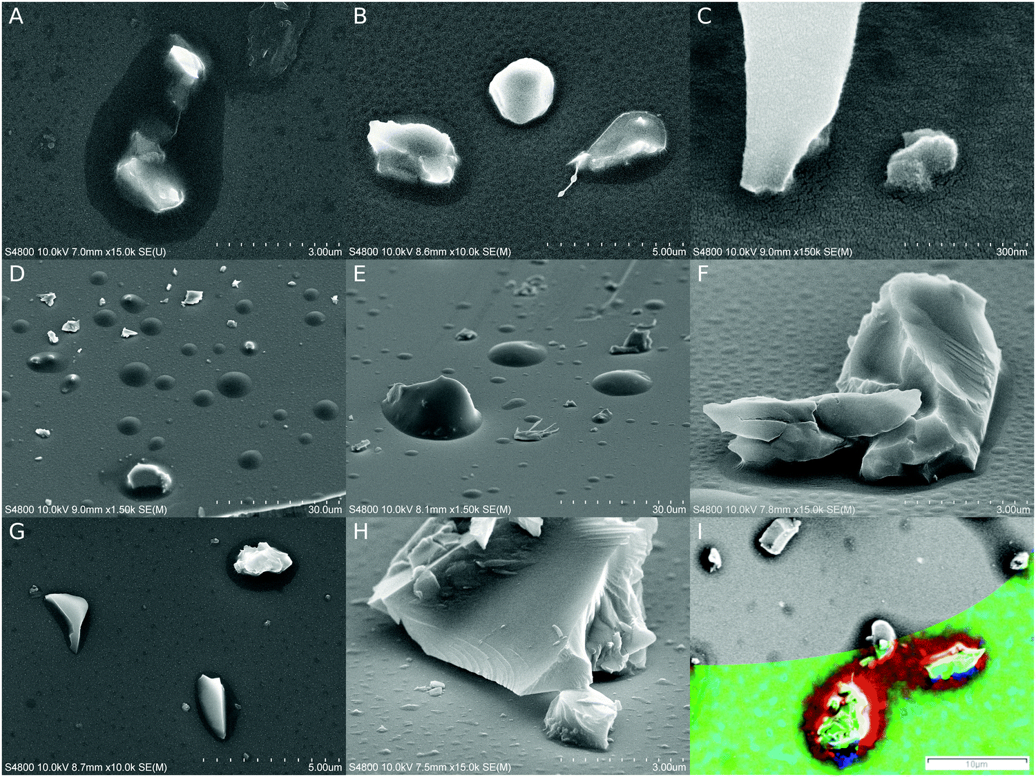 | ||
| Fig. 3 FESEM micrographs of glass substrates. (A–C) 8 min initiation at 95%, 50% and 18% SRs, respectively. (D–F) 15 min initiation at >95%, 50% and 18% SRs, respectively. (G and H) 15 min initiation with added oxygen at 95% and 50% SRs, respectively. (I) Composite image combining an FESEM micrograph (grayscale) and an EDS element map (color). Red: C, green: O, and blue: Si. 15 min UV irradiation at >95% SR, N2 as the carrier gas. | ||
Polymer distribution on the surfaces was estimated with energy dispersive X-ray spectrometry (EDS) as both single point measurements and element mapping on an area. Element mapping (Fig. 3I) did not reveal carbon on open surfaces even on a substrate with the most prevalent CVD growth, the sample with 15 min long initiation at >95% SR. The carbon contents were also analyzed on selected spots on samples which were initiated for 5 and 15 minutes at >95% SR under a nitrogen atmosphere, and they were compared to otherwise similar but untreated glass surfaces (Fig. S3, ESI‡). A significant amount of carbon was detected only in menisci. On the open surfaces the carbon signal was in fact slightly lower than those on the reference surfaces, which might be caused by the UV irradiation during the CSVD procedure purifying the glass surfaces of air-borne organic contamination. However, a small carbon signal above the reference levels was detected in a dark spot which is commonly found on samples after long irradiation times (15 min, Fig. 3I). It is noteworthy that the hypothesized purifying effect might be more pronounced in oxygen containing experiments because the UV lamp is capable of producing ozone out of oxygen.
Experiments with tert-butyl methacrylate (8 min initiation) and styrene (10 min initiation) without added oxygen yielded similar menisci around glass particles to that with ethyl acrylate (Fig. S5A and B, ESI‡). Menisci with styrene on glass were smaller by an order of a magnitude in comparison to (meth)acrylate menisci, possibly due to lower surface wettability by styrene or unintended small variations in the saturation ratios near the saturation point.
4.3. Anodized aluminum oxide (AAO)
As with the other substrates, menisci were formed inside cracks, around particles, below cliffs, and on concave surfaces (Fig. 4A and B: >90% SR, 7–8 min initiation). The surface texture of AAO was visible elsewhere, showing that there was no planarization by polymer overgrowth. However, the experiments were less successful in terms of pore filling. In most cases, a large portion of the pores appeared empty, although their diameters were below the menisci width observed on concave external surfaces. The lack of polymer could partially be due to analytical challenges, because polymer occasionally retracted in the e-beam before any imaging could take place.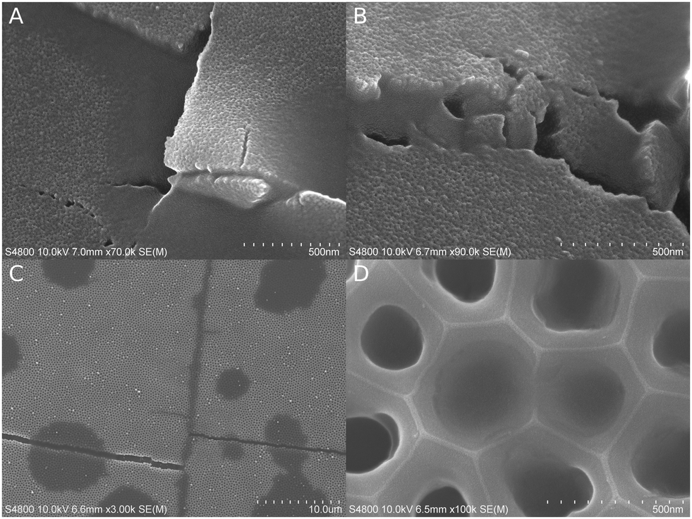 | ||
| Fig. 4 AAO substrates in SEM micrographs. (A and B) CSVD process has prioritized pores, cracks, and even concave surfaces over flat and open planes. (C) Heterogenous CSVD process where feature filling and subsequent planarization proceeded further along cracks than over the surface. (D) Locally successful pore filling. | ||
Sometimes the polymer started to planarize flat external surfaces without obvious condensation caused by a particle or a crack (C; >95%, 8 min UV). The planarized areas formed typically round spots with smooth edges and relatively similar sizes of some microns. Interestingly, polymerization inside the cracks proceeded much farther than in the spots, even up to tens of microns length. The surface was often planarized near a filled crack, much like in the round spots (Fig. 4C). When longer initiation times were attempted, the spots grew in their number and thickness. In some cases, the AAO substrate had randomly dispersed filled pores with a high full/empty pore ratio, but unfortunately no clear tendencies or control over the process could be established at this point. There were many attempts with more complex processes. For example, Fig. 4D shows uneven pore filling in 250 nm wide pores from an experiment, where carrier gas with 2–3% oxygen was used in an attempt to prevent pore overflow by inhibiting surface polymerization. The initiation was 15 minutes long, but the N2 purge was started already after 5 minutes. Nevertheless, pore filling was uneven and the pores appeared empty altogether in many areas.
Experiments with tert-butyl methacrylate (8 min initiation) and styrene (10 min initiation) yielded similar locally successful pore filling to that with ethyl acrylate (Fig. S5C and D, ESI‡).
5. Discussion
The CSVD process worked predictably as polymeric growth was observed to focus inside cracks, corners, pores, and between particles. In addition, in most of the cases there was no observed growth on open surfaces despite better initiation efficiency on exposed surfaces than in shadowed areas. Furthermore, the meniscus size could be controlled by the saturation ratio as predicted by the principle of CC. This feature gives control over the upper cut-off limit of filled feature sizes. The process was easily repeatable for all three monomers and substrates, although with AAO the results were not fully controllable in terms of the degree of pore filling. These properties should make CSVD an important tool for nanoselective coating and filling processes.Acrylic monomers are known to adsorb UV strongly, causing strong reduction in UV intensity beyond depths of several microns.19 However, as shown by the cross-sectional images and implied by the sample stability during SEM and FIB-SEM experiments, UV initiation over just several minutes was adequate in polymerizing the monomer even inside the deepest parts of the samples and also beneath particles. An increase in the initiation time caused polymeric growth on flat open surfaces and polymer overflow from the capillaries, therefore making the process less selective, and thus more (p)iCVD like. This is not surprising, because the process resembles a traditional self-initiated polymeric CVD method during the initiation. However, the primary method of feature filling was CSVD, and not (p)iCVD, as shown by Ni nanopillar substrates, where shorter initiation with SR 96% caused greater growth and filling than longer initiation at 86%. Nevertheless, researching rapid initiation methods also beyond self-initiation by UV would be beneficial for the development of CSVD applications.
Oxygen is known to inhibit radical polymerization25 but it failed to prevent CSVD. When oxygen was added to the carrier gas, it did reduce the extent of growth on open surfaces, but did not prevent polymerization in cavities and other confined locations where CC could occur. This supports the hypothesis that the polymerization is CSVD type by occurring mostly in a condensed liquid phase, because the oxygen/monomer ratio is much lower in bulk liquid monomer than in the gas phase or interfaces. Because liquid monomer is not present on a substrate during a (p)iCVD process, oxygen could be used to increase the selectivity of CSVD over (p)iCVD. Therefore oxygen can be a beneficial additive especially with long initiation times when (p)iCVD becomes a more prevalent growth mode. However, oxygen inhibition is not the only mechanism that increases the CSVD selectivity. Both UV irradiation and ozone produced by UV can also lead to surface cleaning of organic pollutants. Optimizing parameters for oxygen content against initiation efficiency could be useful for improving coating process selectivity for polymers, and it has already been shown to be a critical factor in increasing resolution in the liquid phase.26 In all cases, it can be concluded that rigorous purging of oxygen is not necessary before a CSVD process, which makes the method also industrially more attractive.
The CSVD process was only partially successful for AAO surfaces. Various features induced by surface damage, such as cracks, bends and particles, did acquire a meniscus in or around them. However, the pores in the AAO surface were filled inconsistently. Interestingly, the filled pores were usually located next to each other, typically either in round-edged spot formations or next to a filled crack. This suggests that there was interference between polymerization in neighboring pores, because the random process should lead into filled pores in random locations. The relatively round edges and even spot size distribution suggest that there might also be self-limiting effects, which limit either the maximum spot size or the speed of the spot growth. The spots were only sometimes planarized; therefore, polymer chain growth from pore-to-pore is not a likely explanation in all of the cases. Because the polymerization is an exothermic reaction, heating of the surroundings could be part of the explanation. Heating can situationally either accelerate or decelerate the kinetics of polymerization, and in addition, the heat affects the liquid–vapor equilibrium by promoting evaporation. Interestingly, the CSVD worked well in continuous or interconnected features, such as the interstices in Ni nanopillars or cracks in AAO. Instead, failures occurred inside separate but densely located AAO pores. The partial failure with AAO substrates suggests that controlling the CSVD process is likely more complex than presumed. Therefore further investigation is needed to define how to control the curvature selectivity within various substrates.
The principles and observations found in CSVD could inspire exploration of other methods for added selectivity in VD. Separating mass transfer from adsorbate fixation should allow independent utilization and optimization of the two processes. Thermodynamic phase equilibrium is a useful limiting factor for deposition and it could replace the need to control the monomer sticking rate upon surface impact. Because reaching equilibrium may take different amounts of time at different substrate locations, premature initiation or a parameter swing immediately before initiation could create gradients in the deposition. The heterogeneous nature of the process enables utilization of phase targeting additives such as oxygen in the gas phase to inhibit CVD type growth as shown in this article, or non-volatiles on the surfaces to affect the gas–liquid thermodynamic equilibrium.17 Because the polymerization is done in the bulk, not in a gas–liquid interface as in iCVD, other factors such as gaseous byproduct trapping must be taken into consideration or utilized properly. If feature size is reduced to a low nanometer range, confinement and surface effects become more prevalent and specific adsorption becomes a more important factor over physical adsorption. This could make CSVD converge towards CVD topotaxial self-assembly processes known in molecular sieves.27 Nevertheless, many inherent properties of substrates and confinement effects still remain unexplored.
6. Conclusions
A monomer was allowed to create a thermodynamic, liquid–gas equilibrium inside nanoscaled features before initiating polymerization with UV irradiation. This permitted selective deposition in structures which are difficult or impossible to reach with traditional gas-to-solid deposition methods: inside pores, corners, fractures, below particles, and in their interstices. Because of the phase equilibrium conditions, there were no line-of-sight limitations for the coating and no need for long collision free paths for the adsorbates, and therefore curvature/capillary selective vapor deposition (CSVD) could be applied under normal pressure conditions. Increasing the initiation time made the process shift more towards a traditional non-selective (p)iCVD process. CSVD was not sensitive to small amounts of oxygen. In fact, oxygen reduced undesired CVD growth on external surfaces while allowing a CSVD type of growth in the condensed phase. CSVD was shown to bypass or reverse known challenges in the current CVD methods, and therefore it lays the groundwork for a new surface selective VD paradigm.Author contributions
V. L. developed the CSVD concept, designed and built the reactor setup, planned and carried out all the experiments except for most EDS and FIB experiments, analyzed the results and wrote the initial manuscript draft. M. K. prepared the Ni nanopillar substrates, ran EDS experiments, supervised FESEM experiments and provided feedback. M. V. designed and ran the focused ion beam milling processes. M. L. supervised the research and provided feedback.Conflicts of interest
The authors declare no conflicts of interest.Acknowledgements
Dr Raimo Timonen is gratefully thanked for guidance on the basics of reactor building. Antti Peltonen and Prof. Thad Maloney are gratefully thanked for their support in the preliminary experiments which helped find funding. Dr Jennifer Rowland is gratefully thanked for professional language revision. This research was funded by a doctoral grant from the Doctoral Programme in Materials Research and Nanosciences (MATRENA) and by the Finnish Center of Excellence in Atomic Layer Deposition.References
- Technology Academy Finland, 2018 millennium technology prize for Tuomo Suntola, 2018, available at: https://taf.fi/2018/05/22/2018-millennium-technology-prize-for-tuomo-suntola-finnish-physicists-innovation-enables-manufacture-and-development-of-information-technology-products/, accessed, 14th June 2018.
- K. L. Choy, Chemical vapour deposition of coatings, Prog. Mater. Sci., 2003, 48, 57–170 CrossRef CAS.
- U. Helmersson, M. Lattemann, J. Bohlmark, A. P. Ehiasarian and J. T. Gudmundsson, Ionized physical vapor deposition (IPVD): a review of technology and applications, Thin Solid Films, 2006, 513, 1–24 CrossRef CAS.
- R. W. Johnson, A. Hultqvist and S. F. Bent, A brief review of atomic layer deposition: from fundamentals to applications, Mater. Today, 2014, 17, 236–246 CrossRef CAS.
- E. Charlaix and M. Ciccotti, in Handbook of Nanophysics: Principles and Methods, ed. K. D. Sattler, CRC Press, 2010, vol. 1 Search PubMed.
- A. M. Coclite, et al., 25th anniversary article: CVD polymers: a new paradigm for surface modification and device fabrication, Adv. Mater., 2013, 25, 5392–5423 CrossRef CAS PubMed.
- M. Wang, et al., CVD polymers for devices and device fabrication, Adv. Mater., 2017, 29, 1604606 CrossRef PubMed.
- C. A. Dorval Dion and J. R. Tavares, Photo-initiated chemical vapor deposition as a scalable particle functionalization technology (a practical review), Powder Technol., 2013, 239, 484–491 CrossRef CAS.
- CVD Polymers: Fabrication of organic structures and devices, ed. K. K. Gleason, Wiley-VCH Verlag GmbH & Co., 2015 Search PubMed.
- A. M. Coclite and K. K. Gleason, Global and local planarization of surface roughness by chemical vapor deposition of organosilicon polymer for barrier applications, J. Appl. Phys., 2012, 111, 073516 CrossRef.
- K. Ichiki, B. Altemus, A. Gildea and J. Faguet, Feasibility study into the deposition of an organic planarization layer using sequential polymerization initiated chemical vapor deposition, Thin Solid Films, 2017, 635, 23–26 CrossRef CAS.
- M. E. Alf, et al., Chemical vapor deposition of conformal, functional, and responsive polymer films, Adv. Mater., 2010, 22, 1993–2027 CrossRef CAS PubMed.
- L. Bonnet, et al., Initiated-chemical vapor deposition of polymer thin films: unexpected two-regime growth, Macromol. Mater. Eng., 2017, 302, 1700315 CrossRef.
- F. Begum and S. L. Simon, Modeling methyl methacrylate free radical polymerization in nanoporous confinement, Polymer, 2011, 52, 1539–1545 CrossRef CAS.
- M. Salsamendi, N. Ballard, B. Sanz, J. M. Asua and C. Mijangos, Polymerization kinetics of a fluorinated monomer under confinement in AAO nanocavities, RSC Adv., 2015, 5, 19220–19228 RSC.
- F. Casanova, et al., Effect of surface interactions on the hysteresis of capillary condensation in nanopores, EPL, 2008, 81, 26003 CrossRef.
- M. Yarom and A. Marmur, Capillary condensation with a grain of salt, Langmuir, 2017, 33, 13444–13450 CrossRef CAS PubMed.
- C. Mijangos, R. Hernández and J. Martín, A review on the progress of polymer nanostructures with modulated morphologies and properties, using nanoporous AAO templates, Prog. Polym. Sci., 2016, 54–55, 148–182 CrossRef CAS.
- H. Wang and H. R. Brown, Self-initiated photopolymerization and photografting of acrylic monomers, Macromol. Rapid Commun., 2004, 25, 1095–1099 CrossRef CAS.
- J. Deng, W. Yang and B. Rånby, Auto-initiating performance of styrene on surface photografting polymerization, Macromol. Rapid Commun., 2001, 22, 535–538 CrossRef CAS.
- Dow Chemical Company, How can the occurrence of polymerization in a storage tank be detected? 2018, available at: https://dowservice.custhelp.com/app/answers/detail/a_id/17444/, accessed 19th March 2019.
- Dow Chemical Company, What are the instability and reactivity concerns associated with acrylates? 2018, available at: https://dowservice.custhelp.com/app/answers/detail/a_id/17493/, accessed 19th March 2019.
- L. B. Levy, The inhibition of butyl acrylate by p-methoxyphenol, J. Appl. Polym. Sci., 1996, 60, 2481–2487 CrossRef CAS.
- M. Kemell, V. Pore, J. Tupala, M. Ritala and M. Leskelä, Atomic layer deposition of nanostructured TiO2 photocatalysts via template approach, Chem. Mater., 2007, 19, 1816–1820 CrossRef CAS.
- S. Ligon, B. Husár, H. Wutzel, R. Holman and R. Liska, Strategies to reduce oxygen inhibition in photoinduced polymerization, Chem. Rev., 2014, 114, 557–589 CrossRef CAS PubMed.
- J. R. Tumbleston, et al., Continuous liquid interface of 3D objects, Science, 2015, 347, 1349–1352 CrossRef CAS PubMed.
- C. L. Bowes, A. Malek and G. A. Ozin, Chemical vapor deposition topotaxy in porous hosts, Chem. Vap. Deposition, 1996, 2, 97–103 CrossRef CAS.
Footnotes |
| † The raw/processed data required to reproduce these findings cannot be shared at this time due to technical or time limitations. |
| ‡ Electronic supplementary information (ESI) available. See DOI: 10.1039/c8mh01523f |
| This journal is © The Royal Society of Chemistry 2019 |