
 Open Access Article
 This Open Access Article is licensed under a
 Creative Commons Attribution 3.0 Unported Licence
Green light lithography: a general strategy to create active protein and cell micropatterns†
Dongdong
Xu
,
Solveig M.
Bartelt
,
Samaneh
Rasoulinejad
,
Fei
Chen
and
Seraphine V.
Wegner
 *
*
Max Planck Institute for Polymer Research, Ackermannweg 10, 55128 Mainz, Germany. E-mail: wegners@mpip-mainz.mpg.de
First published on 11th March 2019
Abstract
Micropatterns of functional protein are important in biotechnology and research. Using noninvasive wavelengths, green light lithography allows to photopattern active proteins with high spatiotemporal control. Patterns of light are projected onto a layer-by-layer (LbL) multiprotein film, where the green light cleavable protein CarH is integrated into the first layer. CarH is a tetramer in the dark and dissociates under green light into its monomers. The LbL protein film is designed to have different functional proteins in each layer based on the specific and polyvalent interactions between Ni2+-NTA groups and His-tagged proteins, thus providing oriented protein immobilization under mild conditions to preserve protein activity. This enables the remote release of proteins in the upper layers by exposing the film to green light with 1 μm spatial and 10 s temporal resolution. Green light lithography is successfully used to produce complex patterns of different functional proteins including fluorescent proteins as well as the cell adhesion protein fibronectin. These protein patterns are compatible with cell cultures and the photopatterned fibronectins allow spatial control of cell adhesion. Overall green light lithography provides a flexible way to micropattern His-tagged proteins with high spatiotemporal control and in an oriented way by using noninvasive green light assuring protein function.
Conceptual insightsThe spatial protein patterning provides structural and functional advantages in vast technological applications as well as fundamental research. Here, we describe a layer by layer (LbL) protein film, assembled using the Ni2+-NTA-His-tag interaction and the photocleavable protein CarH, that allows for the local removal of specifically immobilized proteins on demand with high spatial and temporal control. As a proof of concept, this light-responsive LbL protein system is suitable both for the protein and cell patterning applications. This study presents meaningful insights for the assembly of multifunctional protein films which can be used in a wide variety of applications in the field of biomaterials, biosensing, and fundamental cell biology studies. |
Patterning surfaces with active proteins on the micrometer scale is important in many disciplines from biotechnological applications such as tissue engineering, guiding neuronal growth, biosensing and protein chips to fundamental research for the understanding of cell-material interactions and high throughput screenings.1 Micropatterned cell adhesion proteins, for example, define where cells adhere on a material. The protein pattern on the micrometer scale determines which specific signaling pathways are activated in the cell.2 Photolithography, which requires projecting a pattern of light onto a light responsive surface, combines a number of advantages over other micro-fabrication techniques, such as micro-contact printing, lithography and chemical deposition.3–8 Photolithography also provides high spatial and temporal control, is scalable and cost efficient, while being remote controlled, noninvasive and tuneable.
There are two challenges remaining when using the technique of protein photolithography to achieve micropatterns on active and functional proteins: specific immobilization of proteins and the use of noninvasive visible light. The first challenge – specific immobilization: in many photopatterning approaches, the surface chemistry is locally altered through exposure to light, which changes the unspecific adsorption of proteins.9–11 Although widely used, the unspecific adsorption of proteins leads to indiscriminate binding of all proteins in the environment, ill-defined interactions between proteins and substrate, unpredictable unfolding of proteins, and in the worst case inactive orientation on the substrate and loss of activity. To overcome these problems, the specific interactions used to immobilize proteins (e.g. between Ni2+-NTA groups and His-tagged proteins,12–14 biotin and streptavidin,15 as well as glutathione and glutathione S-transferase16) have been rendered light-responsive and photoactivatable chemical dimerizers17,18 have been developed using UV light cleavable caging groups.
The second challenge is that most photopatterning schemes use UV light, which is toxic for cells and damaging to biomolecules. In particular, light cleavable (e.g. nitrobenzenes)19,20 and light switchable (e.g. azobenzenes) moieties,21,22 which have been widely used for unspecific and specific protein patterning, both require the use of UV light, which limits their use in cell biology. There are only a few studies in which researchers were able to photopattern proteins with biocompatible near infrared (NIR) and visible light. The advantage of NIR light is that it can be used for protein photopatterning in 3D using two-photon absorption.16 However, this technique is time-consuming as each point needs to be illuminated sequentially. NIR light can also be used for photopatterning in combination with up converting nanoparticles, which absorb NIR light and emit visible and UV light. For instance up converting nanoparticles were used to locally photocleave a ruthenium complex and the associated unspecifically adsorbed proteins.23 Recently, proteins were also specifically photopatterned with blue light on lipid vesicles and supported lipid bilayer using the blue and red light-dependent interaction between the proteins, which reverses in the dark or far-red light.24,25 While the reversibility of these patterns is of benefit when studying dynamics, many biotechnological applications require permanent protein micropatterns. As a result, there is still a requirement to develop a general approach in order to specifically photopattern active proteins of interest with noninvasive visible light.
One of the major applications of protein micropatterns is the control of cell adhesion to enable studies in cell biology and to discover new possibilities in tissue engineering.26 To date, photopatterning approaches for cells focus on creating local patterns of cell adhesive and repellent regions.27 This has been achieved by coupling UV light responsive photocaging or photoswitchable groups to the cell adhesion peptide RGD, by linking nonadhesive polyethylene glycol (PEG) chains to surfaces through nitrobenzene linkers,28,29 and immobilizing these molecules to up converting nanoparticles.30 In order to go beyond the photopatterning of only adhesion peptides, a general approach is still essential to introduce full length adhesion and signaling proteins to the cell by using noninvasive wavelengths of light.
In this study, we present a versatile method of photopatterning oriented and active proteins with green light using layer-by-layer (LbL) multiprotein films. The LbL multiprotein film allows us to incorporate proteins with distinct functions into different layers depending on the application. For green light photolithography, we used CarH,31,32 a green light cleavable protein, as the light responsive building block. In particular, we integrated CarH into the 1st protein layer to photopattern proteins in the upper layers with green light at high spatiotemporal control (Fig. 1a). Light responsive proteins, like CarH, were employed in the area of optogenetics to control cellular processes noninvasively with light at high spatiotemporal resolution.33 In recent studies, certain light responsive proteins have also been used as useful building blocks to produce light-responsive hydrogels for controlled hydrogel formation, release of p roteins and cells, and also to alter cell migration.34–36
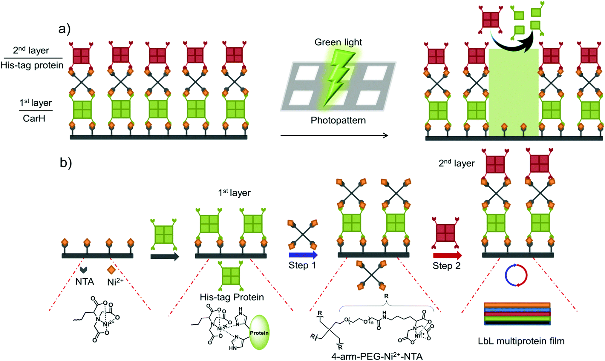 | ||
| Fig. 1 Strategy for green light lithography and the assembly of LbL multiprotein films. (a) The green light cleavable protein CarH, which is a tetramer in the dark, is incorporated into the 1st layer so that proteins in the upper layers can be removed locally by projecting a pattern of green light onto the LbL multiprotein film. (b) The LbL multiprotein films are assembled using the specific and multivalent interactions between 4-arm-PEG-Ni2+-NTA and multimeric His-tagged proteins. A protein with multiple His-tags is immobilized on a Ni2+-NTA functionalized surface to form the 1st protein layer. Subsequent layers are formed by alternately adding 4-arm-PEG-Ni2+-NTA (Step 1) and a protein of interest with multiple His-tags (Step 2). This allows for the assembly of a LbL multiprotein film with different proteins in each layer. | ||
The LbL assembly of films is a simple and versatile way of generating substrates with diverse physicochemical and biological properties.37 In particular, stimuli-responsive (enzyme, pH, temperature, light) LbL coatings have been developed for diverse applications in biosensing, drug delivery, responsive release and cell culture.38–41
Surprisingly, when compared to diverse polymer classes, there are only a few examples of LbL systems with multiple functional proteins, given that different proteins can offer unprecedented functional diversity.42 For the LbL assembly of multiple proteins, we used the specific interaction between Ni2+-NTA groups and His-tags (polyhistidine sequences) of the proteins. This interaction is attractive as it is specific, takes place under mild conditions (in an aqueous buffer at neutral pH and in the presence of other molecules). In addition, NTA modified material as well as His-tagged proteins are readily available. This is the reason why the interaction between Ni2+-NTA groups and His-tags has already been used to assemble a wide variety of protein-based materials ranging from microparticles to hydrogels.43,44
CarH forms a tetramer in the dark when it binds vitamin B12 as its cofactor.31,35,45,46 Under green light illumination, the CarH tetramer dissociates into its monomers. We used this light dependent cleavage of the CarH tetramer into its monomers for the photopatterning of proteins, where we integrated CarH in the 1st layer of the LbL multiprotein films and subsequently were able to locally release proteins in the upper layers by the green light illumination. As a model in this study, we photopatterned the red fluorescent protein TurboRFP and the cell adhesion protein fibronectin (FN).47,48 Photopatterns of FN were then used to pattern cells. Given that the low intensities of green light needed to cleave CarH are not damaging to proteins and cells, it makes this approach highly biocompatible and provides high spatiotemporal remote control.35 Additionally, the specific interactions between the His-tagged proteins and the Ni2+-NTA groups provide specific and oriented protein presentation to preserve protein activity. These results illustrate a versatile strategy for assembling multiple active proteins into LbL films and photopatterning proteins and cells using noninvasive green light.
We began by assembling LbL multiprotein films based on the interaction between His-tags and Ni2+-NTA groups. The assembly of such an LbL film requires multivalent interactions between Ni2+-NTA groups and His-tagged proteins so that the lower and upper layers in the film can be linked to each other (Fig. 1b). Therefore, we used proteins with multiple His-tags oriented in opposite directions, such as the multimeric proteins that carry one His-tag per monomer (MiCy: dimer, TurboRFP: dimer, dKatushka: dimer, CarH: tetramer). To link the His-tagged proteins in each of the different layers, we synthesized and used a 4-arm-PEG (MW 10 kDa) with Ni2+-NTA end groups. As shown in Fig. 1b, proteins with multiple His-tags bind to a surface with Ni2+-NTA groups to form the 1st protein layer. Subsequent protein layers, which form the LbL multiprotein film, are produced by alternately using 4-arm-PEG-Ni2+-NTA (Step 1) and a protein with multiple His-tags (Step 2). It should be noted that the protein in the top layer can be any His-tagged protein and does not need to carry multiple His-tags. In this LbL set up, proteins with distinct functions integrated in each layer will determine the overall functionality of the LbL multiprotein film.
To demonstrate the LbL protein film formation based on the above-described method, we used quartz crystal microbalance with dissipation monitoring (QCM-D). QCM-D is a method commonly used to study the adsorption and desorption of macromolecules on surfaces, where adsorption of molecules onto the crystal is observed as a decrease and desorption as an increase in frequency. In order to form the 1st protein layer, we prepared a PEG-coated SiO2 QCM-D crystal, where the PEG chain has terminal Ni2+-NTA groups, then the dimeric protein MiCy, where each of the monomers carry a His6-tag, was bound to the surface (red arrow) and the excess protein was washed off with buffer (orange arrow) (Fig. 2a). After the 1st protein layer of with MiCy was formed, 4-arm-PEG-Ni2+-NTA solution (Step 1, blue arrow) was passed over the crystal in excess so that Ni2+-NTA groups bind to the free His-tags and Ni2+-NTA groups in other arms remained free for the next protein layer. Notably, upon addition of the 4-arm-PEG-Ni2+-NTA solution there is a slight increase in frequency, which could potentially be due to the sensitivity of QCM-D to changes in viscosity or the removal of some weakly bound proteins from the surface. Subsequently, His6-tagged TurboRFP, dimer, was passed over the surface to form the 2nd protein layer (Step 2, red arrow). By repeating Steps 1 and 2 using a His-tagged dKatushka protein, which is also a dimer, a 3rd protein layer was formed. Further, the QCM-D data could be used to determine the hydrated film by fitting the curves to the Sauerbrey equation. The fitted QCM-D curves give film thicknesses of 4.2, 1.6 and 1.4 nm for the 1st (MiCy), 2nd (TurboRFP) and 3rd (dKatushka) protein layers, respectively (Table S1, ESI†). Considering that the monomeric unit of a fluorescent protein is 3–4 nm in each dimension, it is apparent that the film thicknesses were less than the height of a protein. This finding support the suggested LbL assembly strategy, where a single nonconfluent layer of protein is added to the film in each step due to the specific interaction between the His-tag and Ni2+-NTA groups. When we added an excess of imidazole, which competes with His-tags and disrupts the interaction between His-tag and Ni2+-NTA, the components washed off the surface. This shows that the LbL multiprotein film forms due to the specific interaction between Ni2+-NTA groups and His-tags.
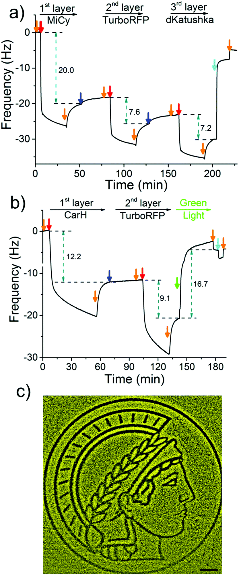 | ||
| Fig. 2 LbL film formation and protein patterning. (a) A 3 protein LbL film is formed on a PEG-Ni2+-NTA functionalized SiO2 QCM-D crystal using 4-arm-PEG-Ni2+-NTA and the dimeric proteins MiCy (1st layer), TurboRFP (2nd layer) and dKatushka (3rd layer). (b) A light-sensitive LbL protein film using the green light cleavable protein CarH (1st layer) and TurboRFP (2nd layer) is formed on a PEG-Ni2+-NTA coated SiO2 QCM-D crystal and removed upon green light illumination. Red arrows: 5 μM of the respective protein, blue arrows: 25 μM 4-arm-PEG-Ni2+-NTA, orange arrows: buffer, cyan arrows: buffer with 250 mM imidazole and green arrow: green light illumination. The 7th overtone is presented. (c) Proteins were locally patterned by projecting the logo of the Max Planck Society, the Minerva, onto a LbL film with CarH (1st layer) and TurboRFP (2nd layer). The removal of the fluorescent protein TurboRFP from the illuminated areas leads to a dark protein pattern on a bright background. Scale bar: 100 μm. | ||
To use green light lithography to produce protein micropatterns, we next integrated the green light-sensitive CarH tetramer into the 1st protein layer in the LbL protein films, so that we could release proteins in the upper film layers after green light illumination when the CarH tetramer dissociates into its monomers. At this point we used the light sensitive C-terminal adenosylcobalamin binding domain of CarH with a C-terminal His6-tag, which is referred to as CarH in the manuscript.31,32 In the dark CarH is a tetramer when it binds to adenosylcobalamin and dissociates into monomers upon exposure to green light due to drastic conformational changes in the protein. For green light lithography, the CarH tetramer was immobilized on the Ni2+-NTA surface through multiple His6-tags (one on each monomer) to form the first layer protein of a LbL protein film. Subsequently, a second protein layer was assembled on top of the CarH tetramer relying on some of the His-tags that are oriented towards the upper part of the film using first 4-arm-PEG-Ni2+-NTA and then a His-tagged protein of choice. Under green light illumination, the CarH tetramer disassembled into its monomers, which broke the linkage between the substrate and the upper layers of the LbL film and lead to the removal of upper protein layers. To integrate the CarH tetramer into the 1st protein layer, we immobilized it on a PEG-Ni2+-NTA functionalized SiO2 QCM-D crystal, followed by QCM-D measurements (Fig. 2b). Next, we produced a 2nd protein layer on top of the CarH tetramer layer using 4-arm-PEG-Ni2+-NTA (Step 1), and followed by His6-tagged TurboRFP (Step 2). Upon green light exposure to the two layer protein film, both CarH and the TurboRFP dissociated from the surface (green arrow). Fitting the QCM-D data to the Sauerbrey equation showed that the CarH and TurboRFP layers were 3.35 and 2.5 nm, respectively and the film thickness reduced to 1.5 nm upon green light illumination (Table S2, ESI†). Upon green light illumination most of the protein was removed from the surface including most of the CarH protein. This is presumably due to the washing off of CarH monomers that were not linked directly to the substrate through their His-tags but to the upper layer Ni2+-NTA-PEG and a reduced avidity of the CarH monomer with a single His-tag compared to the CarH tetramer with four His-tags per protein. This observation was also supported by QCM-D results, where just CarH was immobilized onto a Ni2+-NTA surface and later illuminated with green light. Upon green light illumination surface bound CarH tetramer was almost completely removed from the surface as dissociates into its monomers under green light (Fig. S1, ESI†). Hence, in the LbL multiprotein films the CarH tetramer acts as a green light cleavable linker between the 1st and 2nd protein layers and the protein in the 2nd layer can be flexibly chosen depending on the intended application.
The photocleavable CarH protein layer makes it possible to photopattern complex patterns of a designated protein in the upper layer using noninvasive green light, which we term green light lithography. To demonstrate this, we formed the above-described LbL multiprotein film with CarH and TurboRFP layers on a Ni2+-NTA-PEG coated glass surface. Then, using green light, we projected the logo of the Max Planck Society, Minerva's head, onto it for 60 seconds using a digital micromirror device (DMD, 2048 × 2048, 0.488 μm per pixel). When the sample was fixed and imaged under a fluorescent microscope, we observed dark areas following the projected pattern on a bright fluorescent background (Fig. 2c) indicating that the fluorescent protein TurboRFP was removed from these regions. As a negative control, we immobilized just TurboRFP on the Ni2+-NTA-PEG coated glass surface and projected the same pattern for the same amount of time (Fig. S2, ESI†). This did not result in any pattern formation on the surface, showing that the green light projected by the DMD does not result in significant photobleaching. The observed pattern is due to the light-induced CarH cleavage and the resulting protein dissociation. These results demonstrate a versatile strategy for gaining spatial control of oriented proteins on surfaces and can be flexibly adapted to other His-tagged proteins for the design and production of biosensors and protein chips.
Green light lithography provides both high spatial and temporal control over the produced protein patterns. To demonstrate the spatial resolution that this method provides fine lines of proteins with widths from 100 μm to 1 μm and separated by 20 μm were patterned onto an LbL film containing CarH and TurboRFP described above by projecting 20 μm lines with a 552 nm laser for 10 s using a confocal microscope (0.568 μm per pixel). Dark lines following the projected 20 μm lines with bright areas between them down to 1 μm resolution were observed (Fig. 3a). In contrast, illuminating a pure TurboRFP film (negative control) the same way did not result in any pattern formation (Fig. S3, ESI†). Similarly, 20 μm bright lines with distances of 100 μm to 1 μm between them were patterned on LbL CarH/TurboRFP films, when lines with different widths were projected into the substrate (Fig. 3b). So, both positive and negative protein patterns with a resolution down to 1 μm were attained using green light lithography. The spatial resolution of 1 μm we obtained for green light lithography is comparable to the resolution obtained for UV lithography in conventional setups12–14 but has the clear advantage of using a noninvasive wavelength of light. Theoretically, the minimum feature size is directly proportional to the wavelength and therefore, the resolution for green light lithography (ca. 550 nm) is about two fold lower that for UV (ca. 200–356 nm) lithography. The other important advantage of this method is the high temporal control over protein patterns it offers and the possibility to modify them at a desired time point. To demonstrate this, we first pattered lines of 40 μm widths onto a CarH/TurboRFP LbL film as described above and imaged the protein pattern (Fig. 3c, left). Later at a second time point, we patterned 80 μm lines perpendicular to the first ones on the same substrate, by again illumination for 10 s under the confocal microscope (Fig. 3c, right). Hence, green light lithography does not only allow to pattern proteins with a spatial resolution of 1 μm but also allows for the manipulation of such patterns at a desired time point within 10 seconds.
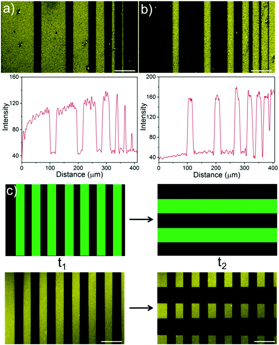 | ||
| Fig. 3 Spatial and temporal control over protein patterns using green light lithography. (a) Protein patterns with thickness of 100 μm to 1 μm (100 μm, 75 μm, 50 μm, 25 μm, 10 μm, 5 μm and 1 μm) separated by 20 μm and (b) 20 μm protein patterns separated by distance from 100 μm to 1 μm on a LbL film with CarH (1st layer) and TurboRFP (2nd layer). Lines of green light corresponding to the dark areas in the protein pattern were projected onto the substrate for 10 s under a confocal microscope. Protein patterns with a resolution down to 1 μm were achieved. Below: Fluorescence intensity profile of the protein patterns. (c) Firstly, 40 μm vertical lines were patterned onto an LbL CarH/TurboRFP film (t1). Subsequently, 80 μm horizontal lines were patterned onto the same substrate (t2), resulting in a cross protein pattern. Hence, protein patterns can be altered at any desired time point. Top: Projected green light pattern, bottom: obtained protein pattern. Scale bar: 100 μm. | ||
The spatial control of proteins on functionalized surfaces is important in order to guide cell-material interactions in general, and cell adhesion in particular, for applications in tissue engineering and to gain a better understanding of cell biology. The possibility of being able to photopattern a protein of our choice motivated us to control cell adhesion through the patterning of the cell adhesion protein fibronectin (FN). To do this, we constructed a LbL protein film where the 1st layer contains CarH and the 2nd layer contains His-tagged FN and observed the forming by QCM-D (Fig. 4a and Table S3, ESI†). As expected, the CarH/FN film is also sensitive to green light and can be removed from the crystal surface by green light illumination (green arrow). Next, we investigated if this CarH/FN film was able to support cell adhesion and if the removal of FN with green light produces nonadhesive surfaces. With this in mind, we incubated MDA-MB-231 cells (5.21 × 10³ cells per cm2) for 4 hours on the Ni2+-NTA-PEG coated glass surfaces with either a CarH/FN film or just FN as a positive control. While one set of surfaces was kept in the dark, another set of surfaces was exposed to green light for 5 minutes before the cells were seeded (Fig. 4b). First, equal numbers of cells adhered to the CarH/FN surface kept in the dark and to the FN modified surfaces. It should be noted that the cells adhered but did not spread on FN or CarH/FN surfaces, presumably due to the low overall FN concentration on the substrate (Fig. S4, ESI†). Secondly, only very few cells adhered to CarH/FN surfaces that had been exposed to green light illumination (1.9% of seeded cells) compared to the CarH/FN surfaces that remained in the dark (25% of seeded cells). In fact, the removal of FN upon green light exposure was very efficient as the number of cells that adhered to green light-exposed CarH/FN surfaces were comparable to the number of cells that adhered to the unmodified Ni2+-NTA-PEG-coated glass surfaces. This reduced cell adhesion on CarH/FN films upon green light illumination was clearly due to the photocleavage of CarH, as cells adhere equally well on pure FN surfaces even when exposed to green light. In summary, these results demonstrate that the CarH can be used to photorelease FN from the surface and hence control cell adhesion by using green light.
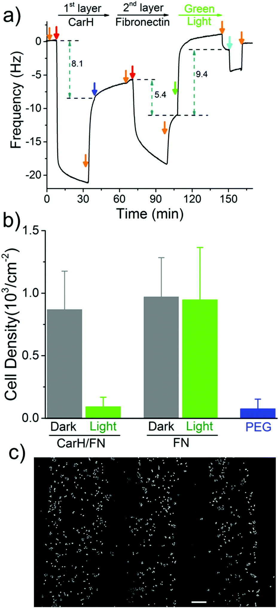 | ||
| Fig. 4 Cell patterning through a patterned fibronectin LbL film. (a) A LbL film with CarH (1st layer) and FN (2nd layer) is formed on a PEG-Ni2+-NTA functionalized SiO2 QCM-D crystal and can be removed upon green light illumination. Orange arrows: buffer, red arrows: 5 μM of the respective protein, blue arrow: 25 μM 4-arm-PEG-Ni2+-NTA, green arrow: green light illumination, cyan arrow: buffer with 250 mM imidazole. The 7th overtone is presented. (b) Quantification of the number of cells that adhere to CarH/FN and FN functionalized surfaces kept in the dark or exposed to green light. Cells cannot adhere to CarH/FN surfaces exposed to green light. (c) Patterned MCF-7 cells on CarH/FN modified surfaces. Cells only adhere to those areas, which were not exposed to green light. Scale bar: 100 μm. | ||
Next, we set out to photopattern FN with green light lithography to locally control cell adhesion on CarH/FN LbL films. For this purpose, we first projected a striped pattern of green light on a CarH/FN LbL film and then seeded MCF-7 cells onto it (Fig. 4c). The MCF-7 cells adhered to the stripes that were not illuminated, but did not adhere to the illuminated regions, indicating the removal of FN in these areas. The cell patterns, which follow the photopatterned FN, show that spatially controlled presentation of active proteins influences cell behaviour such as cell adhesion. These straightforward protein and cell patterns demonstrate that green light lithography allows for the flexible photopatterning of active proteins on different LbL multiprotein films and can be used in a wide variety of applications in the field of biomaterials, biosensing, and fundamental cell biology studies.
To conclude, we have presented a general method for photopatterning of oriented and active proteins using green light on LbL multiprotein assemblies. The ability to photopattern active proteins with noninvasive green light is based on two scientific advancements. To begin with, we were the first to use the green light cleavable protein CarH as a light-sensitive building block for photolithography. This provided us with the desired high spatial and temporal remote control over the protein patterns, while being noninvasive and biocompatible. Secondly, we developed a LbL assembly method for multiprotein films based on the specific and multivalent interaction of Ni2+-NTA groups and His-tagged proteins, which allowed us to achieve the oriented presentation of a His-tagged protein of interest. The specificity of this interaction and the compatibility with buffered solutions at a neutral pH, are key factors in the bioactive presentation of proteins. We focused here on using these multiprotein LbL films to introduce and remove proteins by using green light and by incorporating His-tagged CarH in the 1st protein layer. These LbL multiprotein films can be used for cell patterning, as a promising strategy to modulate cell-material interactions, and to design new biomaterials. The wide availability of His-tagged proteins and Ni2+-NTA-modified materials makes this approach highly modular and adaptable for other applications. A further advantage is that the LbL structure of the multiprotein film can be used to control the sequence of released proteins. Given this, we anticipate that this approach will prove highly useful in applications using protein patterning, drug delivery and tissue engineering.
Conflicts of interest
There are no conflicts to declare.Acknowledgements
We would like to thank the Daimler and Benz Stiftung for their financial support. This work is part of the MaxSynBio Consortium, which is jointly funded by the Federal Ministry of Education and Research (BMBF) of Germany (FKZ 031A359L) and the Max Planck Society. Dongdong Xu would like to thank the Chinese Scholarship Council for his doctoral fellowship. Open Access funding provided by the Max Planck Society.Notes and references
- C. A. DeForest and D. A. Tirrell, Nat. Mater., 2015, 14, 523–531 CrossRef CAS PubMed.
- B. Geiger, J. P. Spatz and A. D. Bershadsky, Nat. Rev. Mol. Cell Biol., 2009, 10, 21–33 CrossRef CAS PubMed.
- J. H. Choe, Q. H. Park and E. A. You, Adv. Funct. Mater., 2016, 26, 5203–5210 CrossRef CAS.
- E. K. Lee, C. H. Park, J. Lee, H. R. Lee, C. Yang and J. H. Oh, Adv. Mater., 2017, 29, 1605282 CrossRef PubMed.
- I. Mironi-Harpaz, L. Hazanov, G. Engel, D. Yelin and D. Seliktar, Adv. Mater., 2015, 27, 1933–1938 CrossRef CAS PubMed.
- J. Wu, C. H. Yu, S. Z. Li, B. H. Zou, Y. Y. Liu, X. Q. Zhu, Y. Y. Guo, H. B. Xu, W. N. Zhang, L. P. Zhang, B. Liu, D. B. Tian, W. Huang, M. P. Sheetz and F. W. Huo, Langmuir, 2015, 31, 1210–1217 CrossRef CAS PubMed.
- J. Wu and J. M. Miao, ACS Appl. Mater. Interfaces, 2015, 7, 6991–7000 CrossRef CAS PubMed.
- J. Wu, C. H. Liow, K. Tao, Y. Y. Guo, X. T. Wang and J. M. Miao, ACS Appl. Mater. Interfaces, 2016, 8, 16368–16378 CrossRef CAS PubMed.
- R. D. Allen, J. Photopolym. Sci. Technol., 2007, 20, 453–455 CrossRef CAS.
- C. Reuther, R. Tucker, L. Ionov and S. Diez, Nano Lett., 2014, 14, 4050–4057 CrossRef CAS PubMed.
- M. Yamaguchi, O. Nishimura, S. H. Lim, K. Shimokawa, T. Tamura and M. Suzuki, Colloids Surf., A, 2006, 284, 532–534 CrossRef.
- M. Bhagawati, S. Lata, R. Tampe and J. Piehler, J. Am. Chem. Soc., 2010, 132, 5932–5933 CrossRef CAS PubMed.
- C. Grunwald, K. Schulze, A. Reichel, V. U. Weiss, D. Blaas, J. Piehler, K. H. Wiesmuller and R. Tampe, Proc. Natl. Acad. Sci. U. S. A., 2010, 107, 6146–6151 CrossRef CAS PubMed.
- N. Laboria, R. Wieneke and R. Tampe, Angew. Chem., Int. Ed., 2013, 52, 848–853 CrossRef CAS PubMed.
- T. Terai, E. Maki, S. Sugiyama, Y. Takahashi, H. Matsumura, Y. Mori and T. Nagano, Chem. Biol., 2011, 18, 1261–1272 CrossRef CAS PubMed.
- V. Gatterdam, R. Ramadass, T. Stoess, M. A. Fichte, J. Wachtveitl, A. Heckel and R. Tampe, Angew. Chem., Int. Ed., 2014, 53, 5680–5684 CrossRef CAS PubMed.
- X. Chen, M. Venkatachalapathy, D. Kamps, S. Weigel, R. Kumar, M. Orlich, R. Garrecht, M. Hirtz, C. M. Niemeyer, Y. W. Wu and L. Dehmelt, Angew. Chem., Int. Ed., 2017, 56, 5916–5920 CrossRef CAS PubMed.
- A. K. Rudd, J. M. Valls Cuevas and N. K. Devaraj, J. Am. Chem. Soc., 2015, 137, 4884–4887 CrossRef CAS PubMed.
- C. A. DeForest and D. A. Tirrell, Nat. Mater., 2015, 14, 523–531 CrossRef CAS PubMed.
- T. T. Lee, J. R. Garcia, J. I. Paez, A. Singh, E. A. Phelps, S. Weis, Z. Shafiq, A. Shekaran, A. Del Campo and A. J. Garcia, Nat. Mater., 2015, 14, 352–360 CrossRef CAS PubMed.
- P. Wan, Y. Wang, Y. Jiang, H. Xu and X. Zhang, Adv. Mater., 2009, 21, 4362–4365 CrossRef CAS PubMed.
- J. Zhang, T. Hu, Y. Liu, Y. Ma, J. Dong, L. Xu, Y. Zheng, H. Yang and G. Wang, ChemPhysChem, 2012, 13, 2671–2675 CrossRef CAS PubMed.
- Z. J. Chen, S. Q. He, H. J. Butt and S. Wu, Adv. Mater., 2015, 27, 2203–2206 CrossRef CAS PubMed.
- S. M. Bartelt, E. Chervyachkova, J. Steinkuhler, J. Ricken, R. Wieneke, R. Tampe, R. Dimova and S. V. Wegner, Chem. Commun., 2018, 54, 948–951 RSC.
- H. Y. Jia, L. Kai, M. Heymann, D. A. García-Soriano, T. Härtel and P. Schwille, Nano Lett., 2018, 18, 7133–7140 CrossRef CAS PubMed.
- T. T. Lee, J. R. Garcia, J. I. Paez, A. Singh, E. A. Phelps, S. Weis, Z. Shafiq, A. Shekaran, A. del Campo and A. J. Garcia, Nat. Mater., 2015, 14, 352–360 CrossRef CAS PubMed.
- N. E. Kurland, T. Dey, S. C. Kundu and V. K. Yadavalli, Adv. Mater., 2013, 25, 6207–6212 CrossRef CAS PubMed.
- J. Auernheimer, C. Dahmen, U. Hersel, A. Bausch and H. Kessler, J. Am. Chem. Soc., 2005, 127, 16107–16110 CrossRef CAS PubMed.
- L. F. Kadem, M. Holz, K. G. Suana, Q. Li, C. Lamprecht, R. Herges and C. Selhuber-Unkel, Adv. Mater., 2016, 28, 1799–1802 CrossRef CAS PubMed.
- W. Li, J. S. Wang, J. S. Ren and X. G. Qu, J. Am. Chem. Soc., 2014, 136, 2248–2251 CrossRef CAS PubMed.
- M. Jost, J. Fernandez-Zapata, M. C. Polanco, J. M. Ortiz-Guerrero, P. Y. T. Chen, G. Kang, S. Padmanabhan, M. Elias-Arnanz and C. L. Drennan, Nature, 2015, 526, 536–541 CrossRef CAS PubMed.
- R. J. Kutta, S. J. O. Hardman, L. O. Johannissen, B. Bellina, H. L. Messiha, J. M. Ortiz-Guerrero, M. Elias-Arnanz, S. Padmanabhan, P. Barran, N. S. Scrutton and A. R. Jones, Nat. Commun., 2015, 6, 7907 CrossRef CAS PubMed.
- D. Tischer and O. D. Weiner, Nat. Rev. Mol. Cell Biol., 2014, 15, 551–558 CrossRef CAS PubMed.
- S. Lyu, J. Fang, T. Duan, L. Fu, J. Liu and H. Li, Chem. Commun., 2017, 53, 13375–13378 RSC.
- R. Wang, Z. G. Yang, J. R. Luo, I. M. Hsing and F. Sun, Proc. Natl. Acad. Sci. U. S. A., 2017, 114, 5912–5917 CrossRef CAS PubMed.
- X. T. Liu, X. Yang, Z. G. Yang, J. R. Luo, X. Z. Tian, K. Liu, S. Z. Kou and F. Sun, ACS Appl. Nano Mater., 2018, 1, 1579–1585 CrossRef CAS.
- J. J. Richardson, M. Bjornmalm and F. Caruso, Science, 2015, 348, 2491 CrossRef PubMed.
- J. Borges, L. C. Rodrigues, R. L. Reis and J. F. Mano, Adv. Funct. Mater., 2014, 24, 5624–5648 CrossRef CAS.
- C. Monge, J. Almodovar, T. Boudou and C. Picart, Adv. Healthcare Mater., 2015, 4, 811–830 CrossRef CAS PubMed.
- R. R. Costa and J. F. Mano, Chem. Soc. Rev., 2014, 43, 3453–3479 RSC.
- P. K. Deshmukh, K. P. Ramani, S. S. Singh, A. R. Tekade, V. K. Chatap, G. B. Patil and S. B. Bari, J. Controlled Release, 2013, 166, 294–306 CrossRef CAS PubMed.
- D. Pallarola, C. von Bildering, L. I. Pietrasanta, N. Queralto, W. Knoll, F. Battaglini and O. Azzaroni, Phys. Chem. Chem. Phys., 2012, 14, 11027–11039 RSC.
- V. Hernandez-Gordillo and J. Chmielewski, Biomaterials, 2014, 35, 7363–7373 CrossRef CAS PubMed.
- M. M. Pires and J. Chmielewski, J. Am. Chem. Soc., 2009, 131, 2706–2712 CrossRef CAS PubMed.
- M. Jost, J. H. Simpson and C. L. Drennan, Biochemistry, 2015, 54, 3231–3234 CrossRef CAS PubMed.
- J. M. Ortiz-Guerrero, M. C. Polanco, F. J. Murillo, S. Padmanabhan and M. Elias-Arnanz, Proc. Natl. Acad. Sci. U. S. A., 2011, 108, 7565–7570 CrossRef CAS PubMed.
- T. Iskratsch, H. Wolfenson and M. P. Sheetz, Nat. Rev. Mol. Cell Biol., 2014, 15, 825–833 CrossRef CAS PubMed.
- K. E. Kubow, R. Vukmirovic, L. Zhe, E. Klotzsch, M. L. Smith, D. Gourdon, S. Luna and V. Vogel, Nat. Commun., 2015, 6, 8026 CrossRef CAS PubMed.
Footnote |
| † Electronic supplementary information (ESI) available. See DOI: 10.1039/c9mh00170k |
| This journal is © The Royal Society of Chemistry 2019 |