Effect of ethylene carbonate on the ionic conduction in poly(vinylidenefluoride-hexafluoropropylene) based solid polymer electrolytes
S.
Ramesh
* and
Ong Poh
Ling
Faculty of Engineering & Science, Universiti Tunku Abdul Rahman, Setapak, 53300, Kuala Lumpur, Malaysia. E-mail: ramesh@utar.edu.my; Fax: +60-3-4107-9803; Tel: +60-3-4107-9802
First published on 5th February 2010
Abstract
Polymer electrolytes based on poly(vinylidenefluoride-hexafluoropropylene) (PVdF-HFP) as the polymer host, lithium trifluoromethanesulfonate (LiTf) as the salt and ethylene carbonate (EC) as the plasticizer, has been prepared by a solution casting technique. Addition of LiTf resulted in an increase in the electrical conductivity of polymer. EC will act to increase the degree of salt dissociation and also ionic mobility. The highest ionic conductivity achieved at room temperature was for PVdF-HFP + LiTf![[thin space (1/6-em)]](https://www.rsc.org/images/entities/char_2009.gif) :EC (60:40) with the conductivity ∼10−3 S cm−1. The conductivity of the polymer electrolyte increases with the increase in amount of plasticizer. The interaction of the PVdF-HFP, LiTf and EC were analyzed by Fourier transform infared (FTIR). The temperature dependent conductivity, frequency dependent conductivity, dielectric permittivity (ε/) and modulus (M/) studies were carried out. Thermo gravimetric analysis (TGA) reveals that the thermal stability of polymer electrolytes decreases with the increase in EC content.
:EC (60:40) with the conductivity ∼10−3 S cm−1. The conductivity of the polymer electrolyte increases with the increase in amount of plasticizer. The interaction of the PVdF-HFP, LiTf and EC were analyzed by Fourier transform infared (FTIR). The temperature dependent conductivity, frequency dependent conductivity, dielectric permittivity (ε/) and modulus (M/) studies were carried out. Thermo gravimetric analysis (TGA) reveals that the thermal stability of polymer electrolytes decreases with the increase in EC content.
1. Introduction
Polymer electrolytes have received great attention due to their potential application in various electrochemical devices particularly in solid-state rechargeable lithium batteries. Compared with liquid electrolytes, polymer electrolytes offer flexibility, shape versatility and have prospective advantages in the continuing trend towards miniaturization.1The development of polymer electrolytes has gone through three stages which are dry solid-state polymers, gel/plasticizer polymer electrolyte systems and polymer composites.
The first example of a dry solid polymer electrolyte is the poly(ethylene oxide) PEO which showed very low ambient temperature conductivities of the order of 10−8S cm−1. The poor performance of the cell was attributed to the poor ionic conductivity of the electrolytes.2
The second category of polymer electrolyte is known as a gel polymer electrolyte or plasticized polymer electrolyte which is neither liquid nor solid and conversely both liquid and solid.3 Both the cohesive properties of solid and the diffusive properties of the liquids give unique characteristics, causing the gel to find various important applications including in polymer electrolytes.4 Composite electrolytes are a subset of polymer electrolytes with the idea of incorporating electrochemically inert fillers into polymer matrices.
In order to enhance the room temperature ionic conductivity of the polymer electrolytes, several methods have been developed which include incorporation of organic solvents, doping inorganic fillers, synthesizing new polymers and preparing various organic-inorganic hybrids. A common method is to add liquid plasticizers such as EC to the polymer matrix to form gel polymer electrolytes.1
These plasticizers will increase the flexibility of the polymer chain and enhance the ionic conductivity. Plasticization has been recognized as one of the effective and efficient routes available for reducing the crystallinity and also enhancement of the amorphous nature of the composite polymer electrolytes.5
The effect of plasticizer on the polymer electrolyte strongly relies on the specific nature of the plasticizer, including the dielectric constant, polymer-plasticizer interaction and ion-plasticizer coordination. The choice of choosing ethylene carbonate (EC) instead of PC and DMC is because it has superior properties when compared to other organic solvents, including a high dielectric constant (89.1), a high donor number (16.4) and also a high boiling temperature (248 °C).6
PVdF-HFP has been intensively investigated because of their various appealing properties like high dielectric constant, low glass transition temperature and low crystallinity. It possesses excellent chemical stability due to VdF unit and plasticity due to HFP unit.1 Ionic conduction in polymers is considered to be caused by the diffusion of the ion through their free volumes. Many polymers dissolve salts to form mixtures which support ionic conductivity. Low lattice energy is required to facilitate the ionization of the salt. In our study, LiTf was chosen as the salt since it possesses low lattice energy, excellent safety and stability characteristics.7,8
The present work aims to characterize PVdF-HFP based polymer electrolytes mixed with LiTf and EC at various composition ratios and temperatures. The characterization performed is to study conductivity, temperature dependent conductivity, thermal stability, dielectric relaxation and modulus. FTIR analysis was performed to investigate the interaction between PVdF-HFP, LiTf and EC.
2. Experimental
Materials
PVdF-HFP was obtained from Fluka, LiTf and EC were obtained from Aldrich and acetone was obtained from J.T. Baker.Preparation
All the thin films of polymer electrolytes were prepared by a solution casting technique. Prior to the preparation of the polymer electrolytes, LiTf was dried at 100 °C for 1 h to eliminate trace amounts of water in the material. 60 wt% of PVdF-HFP and 40 wt% of LiTf were dissolved in 25 ml acetone. Then different wt% of EC were added and further stirred for 24 h at 25 °C to make a homogenous solution. The designation of polymer films is listed in Table 1. The resulting solutions were then poured into the glass petri dishes and allowed to dry in the fume hood at room temperature for 2 days. This procedure yields free standing and mechanically stable films. The thickness of the films can be measured by using micrometre screw gauge.:EC) and ionic conductivity as a function of EC concentration at room temperature
Instrumentation
3. Results and discussion
3.1 Conductivity studies
The ionic conductivity of the membrane is calculated from the following equation:| σ = L/RbA |
Table 1 shows the variation of ionic conductivity values of PVdF-HFP + LiTf:EC polymer complexes as a function of EC concentration at room temperature. When the percentage of EC in the polymer complexes increases from 10 wt% to 40 wt%, the ionic conductivity also increases. The sample with the highest conductivity is PE-40, which has ionic conductivity of 1 × 10⁻³ S cm−1.
Addition of EC to PVdF-HFP + LiTf complexes is expected to increase the degree of salt dissociation and thus produce more ions. The dissociation condition of the salt and the carrier mobility are dominated by the properties of the polymer and solution. The overall ion conductivity is determined by the dissociation of salt, and ion mobility is governed by the polymer, the viscosity and the plasticizers dielectric constant.9
Incorporation of the plasticizer, namely EC, gives rise to a possible change of the chain conformation upon coordination with the solvent and in the ion conducting interfacial phase flexibility. This was confirmed by the disappearance in the degree of crystallinity and with the appearance of the relatively higher degree of the amorphicity, in previous studies conducted. Thus it results in a swelling of the polymer itself.10
The effect of chain mobility on ionic conductivity could be generally correlated to the free volume of the polymer. As the free volume within the polymer increases, rotation of polymer chain occurs more readily, and ion transport in polymer electrolytes is more rapid. Thus, the purpose of adding a plasticizer is to increase the free volume of polymer electrolytes, resulting in increasing ionic conductivity. The presence of the plasticizer increases the ionic mobility by lowering the viscosity of the ionic environment and that in turn results in high conductivity at room temperature. In the plasticized electrolyte, the Li+ ions become coordinated to both the polymer and the plasticizer. There are also some interactions between the polymer chain and plasticizer molecules.
The results suggest that ion transport through the swollen polymer is via diffusion of the small EC molecules, and via the solid polymer network region.11 The higher degree of amorphicity will provide more free volume for the mobility of ions. This subsequently enhances the conductivity of the plasticized polymer electrolyte system.
The ionic conductivity is also determined by the amount of solution entrapped by the membrane. The liquid phase that is entrapped in between the polymer chain will increase with the increasing amount of EC and this will lead to the enhancement of ionic conductivity. The amount of liquid electrolyte trap in the gel membrane was largely dictated by the thickness of the membrane and the conductivity of the non-aqueous electrolyte solution used.12
Besides this, glass transition temperature (Tg) is a function of rotational freedom. According to previous studies, when the polymer complexes react with plasticizer, the Tg can be reduced due to the weakening of the dipole–dipole interactions between the PVdF-HFP in the presence of the plasticizer. This then makes the amorphous state become more flexible and the mobility of charge carrier is increased with the improvement of the segmental mobility.13
3.2 Temperature dependent conductivity studies
The dependence of ionic conductivity of polymer electrolytes on the temperature in the range from 30 to 80 °C is shown in Fig. 1. The figure exhibits a curved nature typical of Vogel-Tamman-Fulcher (VTF) behaviour. | ||
| Fig. 1 Variation of log conductivity against reciprocal temperature for PE-10 and PE-40 samples. | ||
As temperature increases, the bulk resistance of the polymer electrolyte decreases. The energy of ion transfer is reduced due to the plasticizer viscosity changes, which reflects in the conductivity. This means that the free volume approach for the ionic movement in the polymer chain leads to higher conductivity.14
The conductivity increase with temperature can be understood in terms of the free-volume model.15 When the temperature increases, the polymer will expand easily and create free volume. The higher temperature will produce more free volume. The conductivity, which is represented by the overall ion mobility and the polymer, is affected by the free volume around the polymer chains.
When the temperature increases, ions, solvated molecules or polymer segment can move into the free volume.16 The segmental motion will either allow the ions to hop from one site to another or provide an alternative for ions to move. The segmental movement of the polymer facilitates the transitional ionic motion. It is clear that the ionic motion is due to ionic transitional motion facilitated by the dynamic segmental motion of the polymer.
As the amorphous region increases, however, the polymer chain needs faster internal modes in which bond rotations create segmental motion to favor inter- and intra-chain ion hoping, thus the degree of conductivity becomes high.9 At the same time, plasticizer contributes to conductivity enhancement by opening up narrow rivulets of plasticizer-rich phases for greater ionic transport. This will generate large free volume of relatively enhanced conducting phases.17
3.3 Conductivity-frequency dependence studies
The logarithmic plot of conductivity against function of frequency is shown in Fig. 2. The low frequency dispersion may be due to space charge polarization.18 The number of mobile ions that is being polarized as the event of charge accumulation at the electrode and the electrolyte interface decreases as the frequency decreases. Whereas at the high frequency region, the mobility of charge carrier is high and it corresponds to the true conductivity. The conductivity increases with the enhancement of the frequency. | ||
| Fig. 2 Variation of log conductivity as a function of frequency for PE-10, PE-20 and PE-40 samples. | ||
Based on the plot we can conclude that the conductivity of the polymer complexes increase as a function of frequency. PE-40 shows the higher range compared to PE-10 and PE-20, thus it gives the highest conductivity as compared with other samples.
3.4 Dielectric relaxation studies
Dielectric constant is the ratio of the permittivity of a substance to the permittivity of free space. Dielectric relaxation studies are a vital tool to show the relaxation of dipole in polymer electrolyte. The real part (ε/) and imaginary part (ε//) of dielectric permittivity curves are shown in Fig. 3 and 4.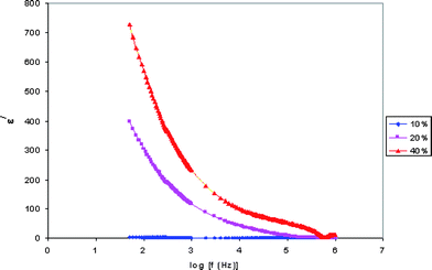 | ||
| Fig. 3 Variation of the real part of the dielectric constant with frequency for PE-10, PE-20 and PE-40 samples. | ||
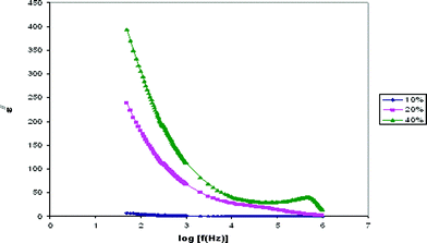 | ||
| Fig. 4 Variation of the imaginary part of the dielectric constant with frequency for PE-10, PE-20 and PE-40 samples. | ||
The observed variation in ε/ with the frequency could be attributed to the formation of a space charge region at the electrode and electrolyte interface. This is well known as the non-Debye type of behavior, where the ion diffusion explains the space charge regions with respect to the frequency.19
The low frequency dispersion region corresponds to the contribution of charge accumulation at the electrode–electrolyte interface. The highest value of ε/ for PE-40 is due to the enhanced charge carrier density at the space charge accumulation region, which causes the equivalent capacitance enhancement. The plot demonstrates that the dielectric constant is high at the low frequencies, and gradually decreases slowly and approaches zero at high frequency. At high frequencies, the periodic reversal of the electric fields occurs so fast that there is no excess ion diffusion in the direction of the field. The polarization due to the charge accumulation decreases, which cause the decrease in the value of ε/.20
3.5 Modulus studies
The dielectric modulus can be understood by relying on the formulation of a dielectric modulus, which has been used to understand the conductivity relaxation.Fig. 5 and 6 show the frequency of the real M/ and imaginary M// part of modulus formalism. It shows that M/ and M// increase towards high frequencies and give a long tail at low frequencies. The peaks in the modulus formalism at high frequencies show that the polymer electrolyte films are ionic conductors. The peak curve at higher frequencies may be due to bulk effect.5
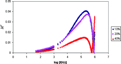 | ||
| Fig. 5 Variation of the real part of the modulus with frequency for PE-10, PE-20 and PE-40 samples. | ||
 | ||
| Fig. 6 Variation of the imaginary part of the modulus with frequency for PE-10, PE-20 and PE-40 samples. | ||
It is observed from the plots that M/and M// decrease towards low frequencies. This is due to the electrode polarization phenomenon which makes a negligible contribution. The plots that show long tails at low frequencies are probably due to their large capacitance values associated with the electrodes. The modulus spectral formalism has facilitated the process of identification and separation of electrode effects from the bulk relaxation phenomena occurring within the plasticized polymer electrolyte system with higher content of EC.5
3.6 Fourier transform infra red studies
Fourier transform infra red (FT-IR) spectroscopy is a useful technique for studying the local structural changes. It can be used to characterize the chain structure of the host polymer and to determine the probable reaction of multifunctional monomers. The spectra of the polymer electrolytes are shown in Fig. 7 and 8. | ||
| Fig. 7 The FTIR spectra for (a) pure PVdF-HFP; (b) pure LITf; (c) pure EC. | ||
 | ||
| Fig. 8 The FTIR spectra for (a) PE-15 and (b) PE-30. | ||
The spectrum of PVdF-HFP containing peaks at 760, 850, 872, 973, 1060, 1146, 1292, 1381, and 1404 cm−1 corresponds to CF3 group, CH2 rocking, CH2 wagging of the vinylidene, out of plane C–H bending, symmetric C–F stretching, CF2 stretching, symmetrical stretching CF3, CH2 wagging and scissoring vibration of vinylidene. The vibrational frequencies appearing at 1060 and 850 cm−1 tend to show the respective crystalline and amorphous phase of PVdF.
The spectrum of LiTf contains peaks at 1264, 1034 and 1180 cm−1 which corresponds to asymmetric SO3, symmetric SO3 and asymmetric CF3. CF3 symmetric deformation and CF3 asymmetric deformation were observed at peak 760 cm−1 and 579 cm−1 respectively. SO3 symmetric deformation and SO3 asymmetric deformation were detected at peak 646 cm−1 and 520 cm−1.21
Upon addition of lithium triflate, a few new peaks have been observed. The new intensities of spectral features observed at 1032 and 640 cm−1 correspond to free SO3− ions and have been gradually reduced for the high concentration of PVdF. It suggests that the number of free triflates becomes fewer.5 A careful analysis of the spectra suggests that the observed vibrational band at 1409 cm−1 corresponds to the deformation vibrational of the CH2 group.22
For pure EC, the C![[double bond, length as m-dash]](https://www.rsc.org/images/entities/char_e001.gif) O peaks were detected at 1798 and 1770 cm−1. The peaks were shifted to higher frequency by around 12 cm−1. This detection corresponds to the specific interaction between the hydrogen in the methylene group of PVdF-HFP and the oxygen in EC which act as Lewis acid and Lewis base. Since the interaction restricts the vibration of CO bond, CO stretching can shift to higher wave number due to absorption. The C–O peak was shown at 1219 cm−1 whereas the CH3 asymmetric peak was found at 2985 cm−1.23
O peaks were detected at 1798 and 1770 cm−1. The peaks were shifted to higher frequency by around 12 cm−1. This detection corresponds to the specific interaction between the hydrogen in the methylene group of PVdF-HFP and the oxygen in EC which act as Lewis acid and Lewis base. Since the interaction restricts the vibration of CO bond, CO stretching can shift to higher wave number due to absorption. The C–O peak was shown at 1219 cm−1 whereas the CH3 asymmetric peak was found at 2985 cm−1.23
Upon addition of EC, a new and less intense band was observed at 716 cm−1 peak. The C–F stretching of CF2 group that found at 1060 and 1174 cm−1 in pure PVdF-HFP disappeared in the complexes, which are suggested to be due to the addition of plasticizer.24
3.7 Thermogravimetric analysis
Thermal stability of polymer films can be studied by thermogravimetric analysis (TGA). The TGA curves for various polymer films are shown in Fig. 9. TGA was done under a nitrogen atmosphere due to the need to purge out oxygen gas to eliminate the reaction that might occur between samples and oxygen gas upon heating. | ||
| Fig. 9 TGA curves for (a) pure PVdF-HFP, (b) PE-10 and PE-40. | ||
The thermogravimetric curves show that the thermal degradation of polymer complex proceeds in two distinct stages. The results show that there is initial weight loss for PE-10 and PE-40 below 100 °C, concluding that both the polymer films contain moisture.
The samples experience first weight loss when the temperature gradually increases from 100–150 °C. This is the temperature where the first decompositions of the polymer complexes start. The reason for this weight loss is due to the scission of the main chains at weak head-to-head linkages.25
The second decomposition that corresponds to the weight loss takes place at the temperature above 400 °C. The reason for this weight loss is due to the thermal degradation of PVdF-HFP units. Chemically the bond strength of C–F is ∼485 kJ mol−1, it is higher than that of C–H bonds (typically 350–435 kJ mol−1) or C–C bonds (typically 350–410 kJ mol−1). High thermal and chemical stability of the thin film are due to the repeating unit –[CF2–CF2]– of PVdF-HFP.26 The total weight loss for pure PVdF-HFP, PE-10 and PE-40 is 37.4%, 54.6% and 63.2% respectively. Therefore, as the amount of plasticizer increases, the total weight loss will increase too. Thus, PE-40, which has the higher plasticizer content, has the lowest thermal stability.
4. Conclusion
The polymer electrolyte system with PVdF-HFP + LiTf:EC (60:40) shows the highest electrical conductivity of 10−3 S cm−1. Addition of the plasticizer EC decreases the crystallinity and increases the degree of amorphicity. The interaction of the electrolyte complexes with EC can be determined by FTIR. The thermal stability of polymer films declines with the addition of EC.
References
- M. Deka, A. K. Nath and A. Kumar, Effect of dedoped (insulating) polyaniline nanofibers on the ionic transport and interfacial stability of poly(vinylidene fluoride-hexafluoropropylene) based composite polymer electrolyte membranes, J. Membr. Sci., 2009, 327, 188–194 CrossRef CAS.
- D. E. Fenton, J. M. Parker and P. V. Wright, Complexes of alkali metal ions with poly(ethane oxide), Polymer, 1973, 14, 589 CAS.
- A. Manuel Stephan, Review on gel polymer electrolytes for lithium batteries, Eur. Polym. J., 2006, 42, 21–42 CAS.
- P. G. Bruce, F. M. Gray, in Solid state electrochemistry, ed.P. G. Bruce , Cambridge University Press, Cambridge( 1995, pp. 119–162 Search PubMed.
- S. Austin Suthanthiraraj, D. Joice Sheeba and B. Joseph Paul, Impact of ethylene carbonate ion transport characteristics of PVdF-AgCF3SO3 polymer electrolyte system, Mater. Res. Bull., 2009, 44, 1534–1539 CrossRef CAS.
- Y. H. Liang, C. Y. Hung and C. C. Wang, Compositional effect of PVdF–PEMA blend gel polymer electrolytes for lithium polymer batteries, J. Power Sources, 2009, 188, 261–267 CrossRef CAS.
- J. Y. Kim and S. H. Kim, Ionic conduction behaviour in network polymer electrolytes based on phosphate and polyether copolymer, Solid State Ionics, 1999, 124, 91–99 CrossRef CAS.
- M. Deepa, N. Sharma, S. A. Agnihotry, R. Chandra and S. S. Sekhon, Effect of mixed salts on the properties of gel polymeric electrolytes, Solid State Ionics, 2002, 148, 451–455 CrossRef CAS.
- C. Y. Chiang, Y. J. Shen, M. Jaipal Reddy and P. P. Chu, Structure, thermal and transport properties of PVAc–LiClO4 solid polymer electrolytes, J. Power Sources, 2003, 123, 222–229 CrossRef CAS.
- T. Aoki, T. Ohta and T. Fujinami, Lithium ion conductivity of gel polymer electrolytes containing insoluble lithium tetrakis(pentafluorobenzenethiolato) borate, J. Power Sources, 2006, 156, 589–593 CrossRef CAS.
- Y. J. Shen, M. Jaipal Reddy and P. P. Chu, Porous PVDF with LiClO4 complex as ‘solid’ and ‘wet’ polymer electrolyte, Solid State Ionics, 2004, 175, 747–750 CrossRef CAS.
- Y. J. Hwang, K. S. Nahm, T. P. Kumar and A. Manuel Stephan, Poly(vinylidene fluoride-hexafluoropropylene)-based membranes for lithium batteries, J. Membr. Sci., 2008, 310, 349–355 CrossRef CAS.
- B. K. Kumar, J. D. Schaffer, N. Munichandraiah and L. G. Scanlon, An electrochemical study of PEO: LiBF4–glass composite electrolytes, J. Power Sources, 1994, 47, 63–78 CrossRef CAS.
- A. Manuel Stephan, K. S. Nahm, M. Anbu Kulandainathan and G. Ravi, Poly(vinylidene fluoride-hexafluoropropylene) (PVdF-HFP) based composite electrolytes for lithium batteries, Eur. Polym. J., 2006, 42, 1728–1734 CrossRef.
- S. Rajendran and T. Uma, Lithium ion conduction in PVC-LiBF4 electrolytes gelled with PMMA, J. Power Sources, 2000, 88, 282–285 CrossRef CAS.
- D. Saikia, Y. W. Chen-Yang, Y. T. Chen, Y. K. Li and S. I. Lin, Investigation of ionic conductivity of composite gel polymer electrolyte membranes based on P(VDF-HFP), LiClO4 and silica aerogel for lithium ion battery, Desalination, 2008, 234, 24–32 CrossRef CAS.
- S. Ramesh and A. K. Arof, Ionic conductivity studies of plasticized poly(vinyl chloride) polymer electrolytes, Mater. Sci. Eng., B, 2001, 85, 11–15 CrossRef.
- A. J. Motheo, J. R. Santos, Jr, A. Sadkowski and A. Hamelin, , The gold (210)|perchloric acid interface: impedance spectroscopy,, J. Electroanal. Chem., 1995, 397, 331–334 CrossRef.
- R. Baskaran, S. Selvasekarapandian, N. Kuwata, J. Kawamura and T. Hattori, ac impedance, DSC and FT-IR investigations on (x)PVAc – (1 − x)PVdF blends with LiClO4, Mater. Chem. Phys., 2006, 98, 55–61 CrossRef CAS.
- S. Ramesh and M. F. Chai, Conductivity, dielectric behavior and FTIR studies of high molecular weight poly(vinylchloride)–lithium triflate polymer electrolytes, Mater. Sci. Eng., B, 2007, 139, 240–245 CrossRef CAS.
- N. S. Mohamed and A. K. Arof, Conductivity studies of LiCF3SO3 doped and DMF- plasticized PVdF-based solid polymer electrolytes, Phys. Status Solidi A, 2004, 201, 3096–3101 CrossRef CAS.
- Z. Li, G. Su, D. Gao, X. Wang and X. Li, In situ scanning tunneling microscopy in electrolyte solutions, Electrochim. Acta, 2004, 49, 4633–4639 CrossRef CAS.
- J. M. Song, H. R. Kang, S. W. Kim, W. M. Lee and H. T. Kim, A porous polymer electrolyte based on P(VDF-HFP) prepared by a simple phase separation process, Electrochim. Acta, 2003, 48, 1339–1346 CrossRef CAS.
- S. Rajendran and P. Sivakumar, An investigation of PVdF/PVC-based blend electrolytes with EC/PC as plasticizers in lithium battery applications, Phys. B, 2008, 403, 509–516 CrossRef CAS.
- N. Katsikis, F. Zahradnik, A. Helmschrott, H. Miinstedt and A. Vital, Thermal stability of poly(methyl methacrylate)/silica nano- and microcomposites as investigated by dynamic-mechanical experiment, Polym. Degrad. Stab., 2007, 92, 1966–1976 CrossRef CAS.
- F. Meier, J. Kerres and G. Eigenberger, Methanol diffusion inwater swollen ionomer membranes for DMFC applications, J. Membr. Sci., 2004, 241, 137–141 CrossRef CAS.
| This journal is © The Royal Society of Chemistry 2010 |