Poly(3-hexylthiophene) bearing pendant fullerenes: aggregation vs. self-organization†
Bobak
Gholamkhass
,
Timothy J.
Peckham
and
Steven
Holdcroft
*
Department of Chemistry, Simon Fraser University, Burnaby, BC V5A 1S6, Canada. E-mail: holdcroft@sfu.ca; Fax: +1 7787823765
First published on 25th February 2010
Abstract
Novel graft copolymers are reported based on poly(3-hexylthiophene) (P3HT) bearing side chains of poly(styrene-stat-chloromethylstyrene), onto which a fullerene C60 or PCBM is covalently attached. P3HT was brominated at the 4-position to various extents (1–30 mol%), subsequently Suzuki-coupled with the boronic ester of 1-(4′-bromophenyl)-1-(2″,2″,6″,6″-tetramethyl-1-piperidinyloxy)ethyl (tempo) to form a nitroxide-functionalized P3HT macroinitiator, which was then used to initiate the nitroxide-mediated radical polymerization (NMRP) of chloromethylstyrene (CMS)-stat-styrene (ST) side chains. CMS units were functionalized with azide units and used to attach fullerene. The polymers contained a relatively high mass content of fullerene (20–41 wt%). Photoluminescence of P3HT is strongly quenched by the fullerene. The absorption of P3HT maximum shifts toward shorter wavelengths with increasing graft density. Films of PCBM/C60 graft copolymers form a bicontinuous morphology with feature sizes <5 nm. Grafting fullerene-bearing side chains directly to P3HT is found to reduce the semi-crystallinity of the P3HT domains, reduce the hole charge mobility, and significantly reduce their photovoltaic activity. This is believed to be due to the poorer solubility of the fullerene units relative to the polymer chains which aggregate during film casting and restricts self-organization of the conjugated polymer.
Introduction
The design and opto-electronic properties of π-conjugated polymers which self-assemble into nanostructured morphologies are currently attracting much attention due to their potential applications in organic photovoltaic (PV) devices.1 Solar conversion efficiencies in excess of 5% are reported for blends of poly(phenylenevinylene)s (PPVs) or poly(3-hexylthiophene)s (P3HTs) with the [6,6]-phenyl C61-butyric acid methyl ester (PCBM).2 The electron donating polymer and electron-accepting fullerene constituents form a nanometre-sized binary network, referred to as a “donor–acceptor (D–A) bulk heterojunction (BHJ).” The D–A interface promotes dissociation of photogenerated excitons into free charge carriers and the bicontinuity of the network provides separate pathways for hole and electron transportation to their respective electrodes.3 The BHJ device is significantly influenced by the purity and bicontinuity of the network, and has been the subject of a number of studies.4P3HT and PCBM are not miscible, and over time, blends of the two may segregate forming discontinuous microscopic domains. The crystallization-driven phase separation is thought to be a cause in the reduction in the D–A interfacial area and photocurrent.5 It is reported that crystallization excludes PCBM from the ordered polymeric domains in bulk heterojunctions.2a,b,6 Durable PV activity thus requires preservation of the BHJ morphology.7 A potential solution is to use copolymers in which the donor and acceptors are covalently bound so as to prevent their large scale segregation. A few examples of this are reported.8 These include a rod–coil diblock copolymer of a poly(p-phenylenevinylene) and a statistical mixture of styrene (ST) and chloromethylstyrene (CMS) bearing C60;9 poly(2,5-di(2′-ethyl)hexyloxy)-1,4-phenylenevinylene attached to C60-functionalized poly(butyl acrylate-stat-chloromethylstyrene);10 a D–A double-cable polythiophene (PT) in which the C60 is attached to the PT backbone through an alkylphenylene linkage to create a PCBM-like structure intended to increase the solubility of the polymer;11 and a diblock copolymer, based on a ring-opening metathesis polymerization of a C60-containing monomer onto an end functionalized P3HT.5 These seminal works provide the impetus for studying how the structure of π-conjugated polymers (πCPs) bearing non-π-conjugated segments determines the morphology of thin films, and in turn, how the morphology and biphasic purity of their thin films determines function, such as photovoltaic activity. Hence, there is a need for systematic approaches to the synthesis of πCP-fullerene copolymers with controlled structure and composition.
Our research group has been investigating synthetic strategies for the versatile modification of πCPs12 and recently reported a design strategy to graft fullerene-bearing side chains onto P3HT.12a This was achieved by post-functionalization of P3HT at the 4-position of the thienyl ring by bromination; initiation of graft polymerization of styrene–4-chloromethylstyrene (ST–CMS); and functionalization of CMS with fullerene by atom transfer radical addition (ATRA) analogous to that described by the Hadziioannou group for the formation of PPV-block-P(ST-stat-(CMS-C60)) linear diblock copolymers.8d,13 Each and every thienyl unit was substituted at the 4-thienyl position—thus demonstrating the completeness of the post-functionalization approach, but this considerably reduced π-conjugation along the PT backbone.
In this report, the effect of controlling the graft density and length of fullerene-bearing side chains (Scheme 1) is explored. The synthetic strategy is based on that described previously12a except for three significant advancements: (1) the graft-chain density (n) is systematically controlled between 1 and 30% (n = 1, 5, 10, 20, 30%, based on the thienyl unit) so as to examine its effect on the opto-electronic properties of the polymers; (2) the Cl functionality on the CMS units in the side chain is converted to azide for more efficient attachment of the fullerene; (3) C60- and PCBM-bearing side chains are investigated—as grafting of PCBM was expected to improve solubility of the copolymers and enable the fullerene content to be determined more accurately by NMR spectroscopy.
 | ||
| Scheme 1 Synthetic route for C60- and PCBM-graft copolymers possessing varying degrees of post-functionalization of P3HT. n: (a) 0.01, (b) 0.05, (c) 0.1, (d) 0.2 and (e) 0.3. | ||
Scheme 1 depicts the synthetic approach to obtain P3HT post-functionalized with side chains of poly(CMS-stat-ST) and the formation of azide functionality. Cycloaddition of the azido group to fullerene completes the synthesis.4c,14 The azido route for the attachment of fullerene, rather than ATRA was used as this was found to be a simpler, versatile method.15 It also avoids crosslinking reactions, preserved the electronic properties of fullerene,16 and could be performed in the absence of catalytic reagents such as Cu, CuBr and bipyridine.17
A comparison of two series of C60- and PCBM-graft copolymers based on post-functionalized P3HT with increasing graft-chain densities (n) is thus provided. Since the P3HT is common to all the derivatives prepared, the degree of polymerization, the polydispersity, and the regio-regularity of the main chain are identical. The styrene to CMS ratio in the graft chain is varied because as the graft-chain density is decreased the number of the grafting sites (CMS) must be increased in order to retain a high mass fraction of fullerene in the final copolymer. In each step of the post-functionalization, the polymers are characterized and compared. The term “systematic” refers to the control of the graft density, which turns out to be a dominant factor.
Experimental section
Materials
4-Bromostyrene, Jacobsen's catalyst and 2,2,6,6-tetramethyl-1-piperidinyloxy (tempo) were purchased from the Aldrich Chemical Co. and used as received. PCBM (>99.5%) was purchased from American Dye Source Inc. and C60 (>99%) from MER Corporation. Styrene and CMS were distilled under reduced pressure prior to use. Chlorobenzene (CB) and 1,2-dichlorobenzene (1,2-DCB) were distilled over anhydrous CaCl2 under reduced pressure. Acetonitrile was stored over molecular sieves 4 Å overnight and distilled from P2O5. P3HT (for fabrication of reference PV devices) was purchased from Reike Metals (regioregularity 90–93%).Instrumentation and procedures
1H and 13C NMR spectra were obtained on 500 and 600 MHz Varian Inova spectrometers (in CDCl3 or CD2Cl2), respectively. Gel permeation chromatography (GPC) was performed using THF (HPLC grade; flow rate of 1 mL min−1 at 165 PSI and room temperature) on a Waters 1515 Isocratic HPLC pump with Waters 2414 refractive index and Waters 2487 absorbance detectors against a polystyrene standard mixture composed of 2.9, 37, 110 and 390 kDa molecular weights. Absorption spectra were recorded on a Cary 3E spectrometer. Photoluminescence (PL) spectra were obtained using a Photon Technology International PTI Felix32 system. The spectra were corrected with respect to the source output and detector response. FTIR spectra were recorded using an ABB FTLA2000 system on samples diluted with KBr and pressed to make 1 cm disks. Cyclic voltammetry was performed using a Princeton Applied Research 263A (WE: glassy-carbon, CE: Pt and REF: Ag wire, −0.01 V vs. SCE). TGA was performed using a scan rate of 20 °C min−1 under nitrogen flow (20 mL min−1) on a Perkin Elmer Pyris 6 TGA system. X-Ray diffraction (XRD) patterns were obtained using a Bruker D8 Advance system. Bright-field TEM images were recorded using a Hitachi 8100 system. Films were spin-coated at 700 rpm from 1,2-DCB and slow-dried on PEDOT–PSS/glass substrate. Thermal annealing was performed on a hot plate at 150 °C for 2 h in a glove box. The films were then floated onto water and placed on a 500 mesh TEM copper grid. Current–voltage (J–V) measurements of devices were conducted on a computer-controlled Keithley 2400 Source Meter. A xenon lamp (300 W, 6258 Newport) equipped with an AM1.5G filter was used as the white light source. The optical power was 100 mW cm−2, measured using a broadband power meter 841-PE (Newport) equipped with an Ophir thermal detector head (3A-P-SH-V1). The power was calibrated versus a Reference Solar Cell (91150V Newport). The external quantum efficiency (EQE) was measured using monochromatic light from a Cornerstone 260 (Newport) and the incident power was measured using a power/energy meter 818-UV (Newport). PV devices were fabricated with the configuration ITO/PEDOT–PSS/graft copolymer/Al(Ca) on patterned and pre-cleaned ITO substrates. The active layer (20 mg mL−1 in 1,2-DCB) was spin-coated in a glove box (O2 and H2O levels <0.1 ppm) with a spin rate of 1000 rpm for 20 seconds preceded by two stages: 100 rpm (1 s); 300 rpm (5 s). Spin-coated films were then left in a covered Petri dish to control the solvent evaporation rate (drying time: 20–40 min) and finally heated to 40 °C for 10 min on a hotplate. The cathode, Ca coated with Al, was thermally deposited through a shadow mask on the active layer using a Varian 3118 thermal evaporator. The active area of the device was 0.1 or 0.2 cm2 depending on the applied mask. The active layer thickness was ∼150 nm while the PEDOT–PSS layer (spin-coated at 5000 rpm and baked at 140 °C for 10 min under ambient atmosphere), Ca and Al thicknesses were typically 40, 20 and 80 nm, respectively, measured using an Alpha-Step IQ profilometer (KLA-Tencor). Although devices were stored in the glove box until measurement, they were exposed to the atmosphere when transferred from the thermal evaporator to the glove box. Fabricated devices were placed in a home-built holder under vacuum for J–V and EQE measurements. For the purpose of hole-mobility measurement, Pd was used as the cathode. The J–V data as a log–log scale were fitted to the space–charge limited current (SCLC) equation. The mobility value was extracted from the intercept when the slope of the log–log plot scaled to 2 in the space–charge limited region. Sample films, for PL and XRD measurements, were spin-coated on either glass or quartz substrates from a 1,2-DCB solution then left in a covered Petri dish for slow evaporation of the solvent. Additionally, for XRD measurements, films drop-cast on quartz substrates from a CB solution followed by slow evaporation of the solvent. The CHCl3 solution for PL measurement was prepared by diluting the stock solution of the graft copolymers (in CB), purged with Ar for 10 min and sealed in cuvettes.Synthesis
Regioregular (RR) poly-3-n-hexylthiophene (P3HT) was prepared by the Grignard metathesis (GRIM) method.18 The general synthetic procedures for the synthesis of macroinitiators and graft polymers are given below and a summary is depicted in Scheme 1.Poly-3-bromo-4-hexylthiophene, 1
N-Bromosuccinimide (0.01 to 0.3 equivalent) was added to a solution of P3HT in CHCl3 under nitrogen. The mixture was stirred at room temperature overnight in the absence of light. The reaction mixture was heated to 50 °C for 2 h after which it was cooled to room temperature and washed with saturated NaHCO3 solution and brine. After separation of the organic layer, the aqueous layer was further extracted with CHCl3 and the combined organic layers dried over MgSO4. The concentrated mixture was poured into methanol and filtered, giving the target compound as a deep violet solid. The crude product was purified by Soxhlet extraction using MeOH and hexane sequentially. The CHCl3 extract was concentrated, poured into methanol and centrifuged. The precipitate was washed with MeOH and vacuum dried.12d A detailed synthetic procedure for poly-3-bromo-4-hexylthiophene (1% Br) 1a; (5% Br) 1b; (10% Br) 1c; (20% Br) 1d; (30% Br) 1e is provided in the ESI†.Tempo (n%)–P3HT macroinitiator (n = 1–30 mol%) (4a–e)
The synthesis of 1-[4-(4′-trimethylene-1,3,2-dioxaborolan-2-yl)phenyl]-1-(2,2,6,6-tetramethyl-1-piperidinyloxyl)ethane 3 from 1-(4′-bromophenyl)-1-(2″,2″,6″,6″-tetramethyl-1-piperidinyloxy)ethyl 2 is described in the ESI†. Partially brominated, poly(3-bromo-4-hexylthiophene) (1a–e), tempo-styrene boronic ester (3) and Pd(PPh3)4 were dissolved in THF and degassed by three freeze–pump–thaw cycles. Under a flow of nitrogen, a degassed solution of K2CO3 (0.2 mmol) in water was added to this mixture through a cannula. The reaction mixture was heated at 60 °C for 2 days under nitrogen after which it was concentrated. The concentrate was poured into MeOH, centrifuged and washed several times with MeOH. The crude precipitate was dissolved in CHCl3 and filtered through a short column of alumina. The dark purple product was reprecipitated upon addition of the concentrate to MeOH, centrifuged and washed several times with MeOH and dried at 50 °C under vacuum. Detailed synthetic procedures for the following macroinitiators: tempo (1%)–P3HT 4a; tempo (5%)–P3HT 4b; tempo (10%)–P3HT 4c; tempo (20%)–P3HT 4d; tempo (30%)–P3HT 4e are reported in the ESI†.P3HT-n%graft-(ST-stat-CMS) (5a–e)
A mixture of tempo (n%)–P3HT (∼40 mg) (4a–e), styrene (2 mL) and CMS (0.50–1.25 mL depending on the desired feed ratio) was purged with nitrogen for 20 min before stirring at 100 °C for 6–24 h. The product was poured into MeOH and centrifuged. The crude product was dissolved in CHCl3 and loaded on a silica gel column. Flash chromatography was performed to remove the styrene homopolymer using an increasing solvent gradient of acetone in MeOH (from 20 to 50 and 100% to remove residual monomers) followed by CHCl3 in acetone (from 10 to 20, 40 and 80% to remove oligomers and/or copolymers of ST–CMS). Finally the product was eluted with CHCl3 and the concentrate poured into MeOH. The product was centrifuged, washed with MeOH and vacuum dried. Detailed synthetic procedures for the following graft copolymers: P3HT-1%graft-(ST-stat-CMS) 5a; P3HT-5%graft-(ST-stat-CMS) 5b; P3HT-10%graft-(ST-stat-CMS) 5c; P3HT-20%graft-(ST-stat-CMS) 5d; P3HT-30%graft-(ST-stat-CMS) 5e are reported in the ESI†.P3HT-n%graft-(ST-stat-N3MS) (6a–e) (where N3MS denotes azidomethylstyrene)
To a solution of ∼100 mg of P3HT-n%graft-(ST-stat-CMS) (5a–e) in CB (70 mL) was added excess amount (4 or more equivalents) of sodium azide in DMF (30 mL). The CB to DMF mixing ratio (70 : 30) was chosen to keep both the polymer and sodium azide dissolved upon mixing. The mixture was heated to 100 °C for 3–6 h under nitrogen. After cooling to room temperature the mixture was poured into MeOH (200 mL) and stirred. The precipitate was centrifuged, washed with MeOH–H2O (4 : 1 v/v) and MeOH sequentially and vacuum dried. The product, if needed, was further purified by Soxhlet extraction using MeOH and hexane sequentially. Detailed synthetic procedures for the following graft copolymers: P3HT-1%graft-(ST-stat-N3MS) 6a; P3HT-5%graft-(ST-stat-N3MS) 6b; P3HT-10%graft-(ST-stat-N3MS) 6c; P3HT-20%graft-(ST-stat-N3MS); 6d; P3HT-30%graft-(ST-stat-N3MS) 6e are reported in the ESI†.P3HT-n%graft-(ST-stat-NMS)-graft-C60 (7b–e)
A mixture of P3HT-n%graft-(ST-stat-N3MS) (6b–e) (typically ∼25 mg) and C60 (∼30 mg) in 50 mL 1,2-DCB was purged with Ar for 30 min and stirred at 110 °C for 1–5 days, depending on the graft density. The reaction mixture was poured into 150 mL of hexane and the precipitate was centrifuged. To remove unreacted fullerene, the crude product was re-dissolved in CB and re-precipitated in hexane 4 times after which the absorption spectrum of the solution remained unchanged. The hexane was decanted and the product was dissolved in CB, sealed under Ar and kept at −10 °C until further use. Detailed synthetic procedures for the following graft copolymers: P3HT-5%graft-(ST-stat-NMS)-graft-C607b; P3HT-10%graft-(ST-stat-NMS)-graft-C607c; P3HT-20%graft-(ST-stat-NMS)-graft-C607d; P3HT-30%graft-(ST-stat-NMS)-graft-C607e are reported in the ESI†.P3HT-n%graft-(ST-stat-NMS)-graft-PCBM (8a–e)
A mixture of P3HT-n%graft-(ST-stat-N3MS) (6a–e) (∼25 mg) and PCBM (∼40 mg) in 25 mL 1,2-DCB was purged with Ar for 30 min and stirred at 110 °C for 1–5 days, depending on the graft density. The reaction mixture was poured into 150 mL of hexane and the precipitate was centrifuged. The crude was re-dissolved in CB and re-precipitated in hexanes 2 times (NMR spectroscopy confirmed the absence of the esteric methyl protons at 3.66 ppm due to free PCBM). The hexane was decanted and the product was dissolved in CB and the vial sealed under Ar until further use. Detailed synthetic procedures for the following graft copolymers: P3HT-1%graft-(ST-stat-NMS)-graft-PCBM 8a; P3HT-5%graft-(ST-stat-NMS)-graft-PCBM 8b; P3HT-10%graft-(ST-stat-NMS)-graft-PCBM 8c; P3HT-20%graft-(ST-stat-NMS)-graft-PCBM 8d; P3HT-30%graft-(ST-stat-NMS)-graft-PCBM 8e are reported in the ESI†.Result and discussion
Polymer synthesis and composition
Regioregular, head-to-tail (HT) coupled P3HT was synthesized using the GRIM method.18 Using 1H NMR integration of the proton at the 4-position of the thienyl ring, the HT regioregularity was found to be >98% with respect to the α-methylene protons (2H at 2.78 ppm). Based on GPC analysis, the number average (Mn) and weight average (Mw) molecular weights, and polydispersity index (PDI) were estimated to be 27![[thin space (1/6-em)]](https://www.rsc.org/images/entities/char_2009.gif) 900, 42700, and 1.53, respectively. A degree of polymerization (DP) of 168 for the P3HT is estimated based on Mn. This P3HT was used to synthesize partially brominated P3HT (1a–e), the tempo (n%)–P3HT macroinitiator (n = 1–30 mol%) (4a–e), the precursor P3HT-n%graft-(ST-stat-CMS) (5a–e), the azide functionalized precursor P3HT-n%graft-(ST-stat-N3MS) (6a–e), the C60 graft copolymer P3HT-n%graft-(ST-stat-NMS)-graft-C60 (7b–e), and the PCBM-graft copolymer P3HT-n%graft-(ST-stat-NMS)-graft-PCBM (8a–e). As an example, the characterization of the 10 mol% post-functionalized P3HT, “c series,” is described here: following partial bromination of P3HT to form 1c, Mn and Mw, increased to 34500 and 57900 Daltons, respectively. For Br-substituted thienyl rings, α-methylene protons appeared at 2.60 ppm in the 1H NMR spectra. The respective peak integration (0.2H) is consistent with 10 mol% post-functionalization of P3HT (see ESI†). Upon reaction of 3 by Suzuki cross-coupling, a new peak at 4.72 ppm evolved exhibiting a quartet multiplicity with a peak integration of 0.1H—attributed to the single proton on the carbon atom juxtapositioned to the oxygen in the tempo group, thus indicating the formation of 4c. The α-methylene protons appeared at 2.60 ppm. Following NMRP of a statistical mixture of CMS and ST, a new set of broad signals at 7.0–7.2, 6.3–6.7, and 4.4–4.6 ppm emerged which are attributed to phenyl and chloromethylene protons on the CMS/ST side chains (5c). Mn and Mw increased to 49300 and 88800 Daltons, respectively, indicative of extensive CMS/ST side chain growth at the 4-position on the thienyl ring. Next, Cl atoms were converted to azide functionalities. 1H NMR spectroscopy confirmed the replacement of all the chlorine atoms by the azide groups (6c). Namely, the broad peak at ∼4.5 ppm, due to methylene groups adjacent to Cl, is shifted to 4.2 ppm. Other protons exhibited the same chemical shifts as 5c (see ESI†).
900, 42700, and 1.53, respectively. A degree of polymerization (DP) of 168 for the P3HT is estimated based on Mn. This P3HT was used to synthesize partially brominated P3HT (1a–e), the tempo (n%)–P3HT macroinitiator (n = 1–30 mol%) (4a–e), the precursor P3HT-n%graft-(ST-stat-CMS) (5a–e), the azide functionalized precursor P3HT-n%graft-(ST-stat-N3MS) (6a–e), the C60 graft copolymer P3HT-n%graft-(ST-stat-NMS)-graft-C60 (7b–e), and the PCBM-graft copolymer P3HT-n%graft-(ST-stat-NMS)-graft-PCBM (8a–e). As an example, the characterization of the 10 mol% post-functionalized P3HT, “c series,” is described here: following partial bromination of P3HT to form 1c, Mn and Mw, increased to 34500 and 57900 Daltons, respectively. For Br-substituted thienyl rings, α-methylene protons appeared at 2.60 ppm in the 1H NMR spectra. The respective peak integration (0.2H) is consistent with 10 mol% post-functionalization of P3HT (see ESI†). Upon reaction of 3 by Suzuki cross-coupling, a new peak at 4.72 ppm evolved exhibiting a quartet multiplicity with a peak integration of 0.1H—attributed to the single proton on the carbon atom juxtapositioned to the oxygen in the tempo group, thus indicating the formation of 4c. The α-methylene protons appeared at 2.60 ppm. Following NMRP of a statistical mixture of CMS and ST, a new set of broad signals at 7.0–7.2, 6.3–6.7, and 4.4–4.6 ppm emerged which are attributed to phenyl and chloromethylene protons on the CMS/ST side chains (5c). Mn and Mw increased to 49300 and 88800 Daltons, respectively, indicative of extensive CMS/ST side chain growth at the 4-position on the thienyl ring. Next, Cl atoms were converted to azide functionalities. 1H NMR spectroscopy confirmed the replacement of all the chlorine atoms by the azide groups (6c). Namely, the broad peak at ∼4.5 ppm, due to methylene groups adjacent to Cl, is shifted to 4.2 ppm. Other protons exhibited the same chemical shifts as 5c (see ESI†).
Integrating the 1H NMR peaks at 4.5, 6.5 and 2.78 ppm of the graft copolymers (5a–e) which correspond to CMS, ST/CMS and α-methylene protons of P3HT, respectively, enabled the degree of functionalization to be determined. For a feed ratio of CMS to ST of 1 : 2, 1 : 3 and 1 : 5 for 5a, 5b–c and 5d–e, respectively, the ratio of CMS : ST per unit of P3HT was found to be 0.5 : 0.6, 1.8 : 3.5, 0.5 : 1.5, 1.2 : 4.8 and 1.1 : 4.1, for 5a, 5b, 5c, 5d and 5e, respectively. NMR analysis indicates that these CMS : ST : P3HT ratios were maintained (<10%) upon conversion of CMS to the azido form (6a–e) and upon further reaction to attach C60 (7b–e) and PCBM (8a–e) (Table 1).
| Compound | n | CMS | ST | C60 or PCBM |
|---|---|---|---|---|
| a Degree of post-functionalization of P3HT (the graft-chain density). b From the integral of the 4.2/4.5 ppm NMR peak. c From the integral of the 3.6 ppm NMR peak. | ||||
| 5a | 1 | 0.50 | 0.60 | — |
| 6a | 1 | 0.50 | 0.60 | — |
| 8a | 1 | 0.17a | 0.60 | 0.08c |
| 5b | 5 | 1.85 | 3.47 | — |
| 6b | 5 | 1.80 | 3.50 | — |
| 7b | 5 | 1.18b | 2.79 | 0.60 |
| 8b | 5 | 1.26b | 3.03 | 0.40c |
| 5c | 10 | 0.46 | 1.46 | — |
| 6c | 10 | 0.52 | 1.46 | — |
| 7c | 10 | 0.15b | 1.42 | 0.37 |
| 8c | 10 | 0.24b | 1.46 | 0.30c |
| 5d | 20 | 1.18 | 4.86 | — |
| 6d | 20 | 1.19 | 5.18 | — |
| 7d | 20 | 0.68b | 4.60 | 0.51 |
| 8d | 20 | 0.60b | 4.60 | 0.33c |
| 5e | 30 | 1.12 | 4.08 | — |
| 6e | 30 | 1.02 | 4.01 | — |
| 7e | 30 | 0.30b | 3.60 | 0.72 |
| 8e | 30 | 0.35b | 4.32 | 0.33c |
NMR spectroscopy was found to be a viable method to quantify the extent of grafting of PCBM in 8a–e. The PCBM content was determined from integration of the broad peak centered at 3.6 ppm attributed to the esteric methyl group of PCBM. Moreover, the successful removal of unreacted PCBM is evidenced by the absence of a sharp singlet (due to esteric methyl protons) at 3.66 ppm. The residue of the peak at 4.2 ppm, particularly for PCBM-graft copolymers, is due to the unreacted –CH2N3 sites and thus can be used, in addition to the peak integration at 3.6 ppm, as a measure of fullerene content. In the case of PCBM-graft copolymers, the corresponding peak of the graft site, i.e., the azamethyl (–CH2N![[double bond, length as m-dash]](https://www.rsc.org/images/entities/char_e001.gif) ; not observable in most cases) at 3.7 ppm overlaps the broad peak for the PCBM methyl ester (centered at 3.6 ppm). For C60-graft copolymers 7b–e, FTIR spectroscopy confirmed a large reduction in intensity of the peak at 2095 cm−1, attributed to the azide functional groups and appearance of a peak at 527 cm−1 (due to C60) indicating the successful cycloaddition of N3 to C60 in 7b–e (see ESI†). In addition, 1H NMR of 7b–e showed that the 4.2 ppm peak integral is reduced in comparison to 5b–e and 6b–e. The C60 content is calculated from the difference in –CH2N3 integration in the azido compounds 6b–e and its residual in the C60-graft copolymers 7b–e. The polymer compositions are summarized in Tables 1 and 2.
; not observable in most cases) at 3.7 ppm overlaps the broad peak for the PCBM methyl ester (centered at 3.6 ppm). For C60-graft copolymers 7b–e, FTIR spectroscopy confirmed a large reduction in intensity of the peak at 2095 cm−1, attributed to the azide functional groups and appearance of a peak at 527 cm−1 (due to C60) indicating the successful cycloaddition of N3 to C60 in 7b–e (see ESI†). In addition, 1H NMR of 7b–e showed that the 4.2 ppm peak integral is reduced in comparison to 5b–e and 6b–e. The C60 content is calculated from the difference in –CH2N3 integration in the azido compounds 6b–e and its residual in the C60-graft copolymers 7b–e. The polymer compositions are summarized in Tables 1 and 2.
| Compound | DP of ST | DP of CMS | P3HT : ST/CMS : fullerene (wt%)a | TGA (wt%)b |
|---|---|---|---|---|
| a Based on 1H NMR integration. b Residue at 800 °C. | ||||
| 5a | 60 | 50 | 55 : 45 : 0 | — |
| 6a | 60 | 50 | 55 : 45 : 0 | — |
| 8a | 60 | 50 | 44 : 36 : 20 | — |
| 5b | 580 | 310 | 26 : 74 : 0 | — |
| 7b | 580 | 310 | 13 : 52 : 35 | 37 |
| 8b | 580 | 310 | 14 : 55 : 31 | — |
| 5c | 250 | 80 | 42 : 58 : 0 | — |
| 7c | 250 | 80 | 20 : 48 : 32 | 20 |
| 8c | 250 | 80 | 20 : 47 : 33 | 32 |
| 5d | 820 | 200 | 20 : 80 : 0 | — |
| 7d | 820 | 200 | 14 : 57 : 29 | 26 |
| 8d | 820 | 200 | 14 : 60 : 26 | 25 |
| 5e | 670 | 170 | 23 : 77 : 0 | — |
| 7e | 670 | 170 | 14 : 45 : 41 | — |
| 8e | 670 | 170 | 16 : 55 : 29 | — |
Of note, the ratio of CMS to styrene is found to be higher than the feed ratio. This is due to the higher reactivity of CMS.8d,e,9,19 For the 1 and 5 mol% functionalized P3HT polymer, 5a and 5b, the NMRP reaction of CMS/ST was performed for 24 h longer than the other copolymers (6 h) in order to prepare longer side chains as a measure to increase the number of (fullerene) grafting sites in order to compensate for the relatively low graft-chain density of the precursor polymers 5a and 5b. The difference in the copolymer compositions as a result of this is observed in Tables 1 and 2.
Decoupled 13C NMR was also used to confirm the structure of the fullerene-graft copolymers, 7b–e and 8a–e. The chemical shifts are well resolved into aliphatic and aromatic regions. Six sharp peaks observed at 14.35, 22.88, 29.49, 29.69, 30.73 and 31.92 ppm are attributed to hexyl chain carbons while broad and less intense peaks at 40.47, 43.08 and 46.24 ppm are due to aliphatic carbons on CMS/ST side chains. The –CH2N carbon appears at 57.80 ppm. For highly functionalized 5–30 mol% graft copolymers, the thiophene carbons are observed between 125–146 ppm in the aromatic region. Instead of a C60 peak, which is usually observed at 143 ppm for “free” C60, a broad peak centered at 145 ppm is observed for the grafted fullerene. For the 1 mol% functionalized graft copolymer 8a, four aromatic carbons at 128.82, 130.70, 133.92 and 140.11 ppm are observed (see ESI†).
The polymers were meticulously purified to the level that free PCBM is not detectable by NMR. Free PCBM provides a sharp NMR signal at 3.66 ppm, whereas PCBM signals attached to the polymer are broadened. A NMR spectrum is provided in the ESI† of a 5 mol% graft copolymer 8b polymer that is not purified of free PCBM. A comparison between this spectrum and that for purified 8b in ESI† (Fig. S4 and S5) demonstrates removal of free PCBM. The fullerene content in the graft copolymers was also quantified by thermogravimetric analysis (TGA). Under nitrogen, the copolymers show minor decomposition at ∼150 °C, most likely due to loss of the unreacted azide functional groups—as a very similar observation for PPV–C60 dyads, synthesized by cycloaddition of an azido group to C60 has been reported.15 The copolymer backbone decomposes between 360 and 500 °C, a temperature range consistent with that reported for a C60-bearing π-conjugated copolymer containing blocks of DEH–PPV and poly(ST-stat-C60MS).9 The decomposition of the graft copolymers is almost complete by 800 °C. The residue at this temperature corresponds to the remaining fullerene. As shown in Table 2, the fullerene content determined from residual masses at 800 °C is in close agreement with those estimated by NMR. Depending on the polymer composition i.e., graft density, CMS : ST ratio and side-chain length, the fullerene constitutes 20–41 wt% of the graft copolymers (Table 2).
Optical properties
Optical absorption and PL quantum yields (ΦPL) of the fullerene-bearing and precursor polymers are summarized in Table 3. UV-Vis absorption spectra of the PCBM-graft copolymers (8a–e) in solution and solid state are shown in Fig. 1. The solid-state absorption spectra of the C60 graft copolymers (7b–e) are provided in the ESI†.| Compound | Solutiona | Films | ||||
|---|---|---|---|---|---|---|
| Abs. max./nm | PL max./nm | Φ PL | Abs. max./nm | PL. max./nm | Φ PL | |
| a Chloroform solution. b Relative to P3HT film. c Broad peak with a shoulder at 660 nm. | ||||||
| P3HT | 440 | 582 | 0.243 | 560 | 718c | 0.01612d |
| 5a | 450 | 581 | 0.194 | 516 | 710c | 0.0067 |
| 8a | 450 | 582 | 0.145 | 546 | 720c | 0.0015 |
| 5b | 440 | 580 | 0.210 | 551 | 655 | 0.0062 |
| 7b | 440 | 581 | 0.080 | 543 | 660 | 0.0002 |
| 8b | 440 | 581 | 0.101 | 540 | 587 | 0.0062 |
| 5c | 440 | 582 | 0.236 | 516 | 662 | 0.0088 |
| 7c | 440 | 582 | 0.123 | 473 | 640 | 0.0002 |
| 8c | 440 | 582 | 0.149 | 490 | 570 | 0.0055 |
| 5d | 430 | 582 | 0.231 | 551 | 648 | 0.0344 |
| 7d | 430 | 582 | 0.067 | 426 | 648 | 0.0004 |
| 8d | 430 | 582 | 0.091 | 433 | 587 | 0.0024 |
| 5e | 420 | 577 | 0.237 | 435 | 606 | 0.0921 |
| 7e | 420 | 577 | 0.025 | 410 | 600 | 0.0054 |
| 8e | 420 | 577 | 0.038 | 411 | 564 | 0.0042 |
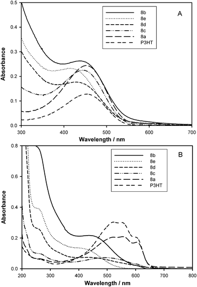 | ||
| Fig. 1 Absorption spectra of PCBM-graft copolymers (8a–e) in (A) chloroform solution and (B) solid state. Film thicknesses for 8a: 20, 8b: 180, 8c: 80, 8d: 70 and 8e: 120 nm. For comparison, absorption spectrum of P3HT is shown. | ||
In solution, the characteristic π–π* transition due to P3HT appears at 450, 440, 440, 430 and 420 nm for the 1, 5, 10, 20 and 30 mol% post-functionalized copolymers, respectively. The absorption maximum thus blue shifts with increasing chain graft density as a result of the systematic disruption of planarity along the backbone and a reduction in long range conjugation. In a D–A double-cable PT copolymer, it was observed that the absorption band edge of the double cable is lower than that of its precursor, which indicates that the presence of C60 groups on the side chains affects the band gap of the PT backbone. The C60 groups prevent the PT main chains from adopting a fully planar conformation.20 The 330 nm absorption band is attributed to the fullerene and intensifies with increasing fullerene content in order of 7c < 7d < 7e < 7b and 8a < 8c < 8d < 8e < 8b, respectively.
The corresponding solid-state absorption spectra of 8a–e are shown in Fig. 1B; spectra for 7b–e are shown in the ESI†. Extensive π–π stacking of P3HT and the formation of an ordered structure—as evidenced by extension of the π–π* absorption band to 650 nm21—is reduced for the 5, 10 and 20 mol% post-functionalized series, 7b–d and 8b–d, and completely absent in the 30 mol% post-functionalized series, copolymers 7e and 8e. The exception is the 1 mol% post-functionalized copolymer, 8a. Increasing the density of side chains and attaching bulky fullerenes clearly interferes with π–π stacking of the thiophene rings, resulting in a higher degree of twisting and non-planarity along the P3HT backbone.20 In an attempt to understand the origin of this effect, the solid state UV-Vis spectra for the “a” and “b” series are shown in Fig. 2. The similarity of the absorption spectra of 1–5b in Fig. 2A indicates that bromination, attachment of the nitroxide initiator, and even the ST/CMS side chains interferes little with organization of the P3HT when the corresponding polymers are cast from solution. However, attachment of C60 (or PCBM, for the case of 8b depicted in Fig. 2A) restricts organization of the backbone when cast from solution, as evidenced by the blue shift and loss of fine features. This loss of fine features is accentuated for the 10, 20, and 30 mol% graft copolymers. In this respect, the solid state absorption spectra of extensively (20–30 mol%) functionalized precursor copolymers, 5d and 5e, shows that even the growth of ST/CMS side chains restricts stacking of the PT backbone to some extent (see Fig. S9 in ESI†). In contrast, the absorption spectra of 1–8a in Fig. 2B for which the post-functionalization is only 1 mol%, are similar, indicating a greater propensity for long range conjugation in P3HT.
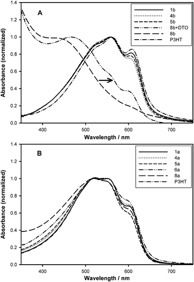 | ||
| Fig. 2 Solid-state absorption spectra of (A) 5% (series b) and (B) 1% post-functionalized graft copolymers (series a). In (A), films of 8b were spin-cast from 1,2-DCB with and without additive, 1,8-octanedithiol (ODT)—the arrow shows the corresponding red-shift in absorbance. P3HT is shown for comparison. | ||
These observations can be explained with use of the representation shown in Fig. 3 that shows two scenarios for aggregation/organization upon solution casting. Two competing forms of aggregation/organization can be anticipated: (1) ordering and semi-crystallization of the P3HT backbone, (2) aggregation of the less soluble fullerene. The evidence presented in Fig. 2A for the 5 mol% functionalized polymer (and >5 mol% functionalized polymers shown in Fig. 1B) indicates that aggregation of fullerene during film formation is dominant. That is, as the solvent evaporates from the spin-cast film, nucleation and precipitation of fullerenes occur—to extent made possible by their attachment to the backbone—with the consequence that the P3HT backbone is placed under stress and torsion so as to limit its self-organization. The same forces are expected to be present in the case of the 1 mol% polymer but the much longer uninterrupted sequence length of the P3HT appears sufficient to enable more extensive organization. However, the effect of aggregation of fullerenes is still present, as will be illustrated later through studies of crystallinity, charge mobility, and PV properties.
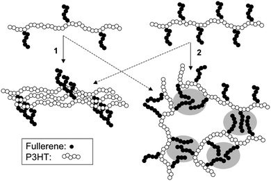 | ||
| Fig. 3 Schematic representation of two competing processes: (1) ordering and semi-crystallization of P3HT which requires the backbone to aggregate/organize first, and (2) aggregation of the less soluble fullerene groups (shaded area) for low (left) and high (right) graft-chain density polymers. The solid arrows show the dominant process for each structural case. | ||
In an attempt to further enhance absorbance in the red-region of the absorption spectrum of 8b in the solid state, a few volume percent of an additive, 1,8-octanedithiol (ODT), was incorporated into the solution of 8b in 1,2-DCB used for spin-casting. The addition of alkanedithiols into the solvent was recently shown to improve the performance of BHJ solar cells.22 Shown in Fig. 2A are the absorption spectra of the graft copolymer 8b with and without 5 vol% ODT. As can be seen, the absorption spectrum obtained for a copolymer film developed from a solution containing ODT is red-shifted showing several vibronic side bands at ∼500, 550 and 600 nm. Lee et al. argued that the alkanedithiol functions as a processing additive.22b It selectively dissolves the fullerene-end of the graft copolymer. ODT has a higher boiling point (270 °C) than 1,2-DCB and, therefore, the fullerene-end tends to remain in solution longer than the thiophene backbone allowing it to be “deposited first”. A longer drying time may also result in a control of the phase separation in the graft copolymers. However, a morphological study performed on films developed with and without added ODT indicated that both films possessed identical features (see below).
In chloroform solution, graft copolymers display a fluorescence maximum at 580, 581, 582, 582 and 577 nm for series a, b, c, d and e, respectively, i.e., for 1, 5, 10, 20 and 30 mol% post-functionalization, irrespective of the nature of the side chain. Representative PL spectra for the PCBM-bearing polymers (8a–e) are shown in Fig. 4 (for the precursor P3HT polymers bearing poly(CMS-stat-ST) side chains (5a–e) and the C60-graft copolymers (7b–e) see Fig. S10 in ESI†). Compared to P3HT, a 5 nm blue shift in the photoluminescence (PL) maximum is observed for the 30 mol% post-functionalized copolymers (e series), due to a reduction in long range conjugation, as explained for the UV-Vis absorption spectra. The PL maxima in each series are identical; for instance, for the 30 mol% post-functionalized copolymers, i.e., 5e, 7e and 8e, the PL maximum is 577 nm. The comparison of the PL peak positions for the precursor copolymers, 5b–e, to those of the C60- and PCBM-graft copolymers, 7b–e and 8b–e, illustrates that grafting the fullerene has no inherent effect on the emission wavelengths of the copolymers in solution.
 | ||
| Fig. 4 PL spectra of the PCBM-graft copolymers (8a–e) and P3HT in chloroform (A) and solid state (B). | ||
Φ PL provides more detailed insight into the structure-property relationships. ΦPL of the copolymers in solution are compared from three different viewpoints: (1) when ΦPL values within a series of graft copolymers of a particular graft density, e.g., 1, 5, 10, 20 or 30 mol% post-functionalization are compared, ΦPL is found to be extensively quenched when C60- or PCBM is attached. For example, in solution, 7e and 8e, exhibit ΦPL values of 0.025 and 0.038, respectively, compared to the precursor copolymer 5e (ΦPL, 0.23) and the pristine P3HT (0.24). Quenching of PL intensity from P3HT by fullerene is due to photoinduced electron transfer from P3HT to the C60 or PCBM.23 (2) ΦPL decreases with increasing graft-chain density. For example, ΦPL for PCBM-graft copolymers 8a, 8c, 8d and 8e are 0.20, 0.15, 0.091 and 0.038, respectively. The 5 mol% PCBM-graft copolymer (8b, ΦPL = 0.10) is an anomaly as this particular sample bears much longer poly(CMS-stat-ST) side chains and possesses a higher PCBM content. (3) PL quenching in the C60-graft copolymers (7b–e) is found more efficient than the corresponding PCBM-graft polymers (8b–e), and is simply attributed to their higher relative C60 contents.
The PL properties in the solid state, i.e., maxima and ΦPL listed in Table 3, are influenced by two parameters: graft-chain density and fullerene content. For the precursor copolymers 5a–e, the PL data indicate that a higher degree of post-functionalization results in a larger blue shift as well as an increase in ΦPL in traversing the series 5a to 5e. Interestingly, for the precursors 5d and 5e the ΦPL (0.0344 and 0.0921, respectively) are even larger than that of P3HT (0.016). These are the consequences of reduced interchain interaction caused by limited self-organization of the P3HT backbone. On the other hand, the PL of the fullerene-graft copolymers 7b–e and 8a–e is extensively quenched. The PL maxima are influenced by the graft-chain density and fullerene content which control the self-assembling processes as schematically explained in Fig. 3. There is a clear relationship between the PL maximum and ΦPL in solid state which obeys the energy gap law: the larger the gap in energy the higher the ΦPL. However, ΦPL is also affected by the grafted fullerene thus the observed relationship between PL maxima and ΦPL is not a simple one.
Quenching of PL by fullerene in films of the graft copolymers is even more efficient than in solution. For example, ΦPL for 8e in solution and the solid state is 0.038 and 0.004 respectively, whereas in the solid state ΦPL for P3HT is 0.016.12d This is due, in part to facile migration of excitons in the solid state P3HT, which occurs in tens of ps,24 the higher molar volume of the fullerene in the condensed phase compared to isolated polymer chains in solution, and the fast rate of photoinduced electron transfer, which occurs on the sub-ps time scale.23
Electrochemical properties
The effect of polymerizing side chains on P3HT and the subsequent attachment of fullerene on the redox properties of the polymers are summarized in Table 4, which lists the oxidation onset (Eonset) and reduction cathodic-peak potentials (Epc) for the graft copolymers.| Copolymer | E onset (oxidation)/V | E pc (reduction)/V | |
|---|---|---|---|
| a Chlorobenzene and dichloromethane (2 : 1 v/v) containing 0.1 M TBAClO4vs. Ag wire, scan rate of 100 mV s−1. E1/2 for Fc/Fc+ couple was observed at 0.487 V. | |||
| 7b | 0.57 | −0.68 | −1.09 |
| 7c | 0.58 | −0.68 | −1.10 |
| 7d | 0.64 | −0.68 | −1.10 |
| 7e | 0.68 | −0.70 | −1.10 |
| 8b | 0.62 | −0.81 | −1.16 |
| 8c | 0.59 | −0.71 | −1.05 |
| 8d | 0.65 | −0.71 | −1.06 |
| 8e | 0.74 | −0.76 | −1.12 |
Cyclic voltammograms of the copolymers are provided in the ESI† (Fig. S11 and 12). The C60-bearing graft copolymers show two sequential, reversible cathodic waves due to fullerene reduction with peak potentials (Epc) at approx. −0.68 and −1.10 V vs. Ag (−0.01 V vs. SCE). PCBM-bearing polymers also yield two reversible waves due to the fullerene within the same potential window. The first reduction peak potentials for 8b–e range between −0.71 and −0.81 V; those for 7b–e range between −0.68 and −0.70 V. The onset of the quasi-reversible oxidation of the P3HT main chain ranged from 0.57–0.74 V. Generally, increasing the graft-chain density and the fullerene content shifts the onset to more positive potentials, e.g., for the 7b–e series, from 0.57 to 0.68 V; and for the 8c–e series, from 0.59 to 0.74 V. The shift in oxidation potential is more pronounced in graft copolymer with higher degree of post-functionalization as a consequence of the increasing distortion and non-planarity of the main chain and widening of the HOMO–LUMO band gap, which is consistent with the wavelength shifts observed in the absorption spectra.
Morphology
The morphology of fullerene-bearing copolymers in the solid state was examined in the form of thin films by transmission electron microscopy (TEM). All showed evidence of a binary network of P3HT and fullerene. Bright-field TEM images of the precursor, 5d, and the graft copolymers, 8d and 8e, are shown in Fig. 5, as examples.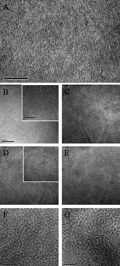 | ||
| Fig. 5 TEM images (scale bar: 100 nm) of 5d (A), 8d before (B) and after annealing at 150 °C for 8h (C), 8e before (D) and after annealing for 3h (E), and P3HT : PCBM (1 : 1) before (F) and after annealing for 3 h (G). In (B) and (D), insets show a higher magnification (scale bar: 50 nm). | ||
Also shown in Fig. 5, for comparison, is a similar image obtained for a molecular blend of P3HT and PCBM (1 : 1 wt% ratio). The TEM image of 5d shows dark and bright regions, which represent the semi-crystalline P3HT and amorphous poly(CMS-stat-ST) domains, respectively. For 8d, the contrast between these regions is reduced due to presence of grafted PCBM in the poly(CMS-stat-ST) domains, as a result of the higher density of carbon atoms, but the nano-phase segregated domains are still visible. Typical domain sizes are in the range of 5 nm, which is considerably smaller than that usually observed for molecular blends of P3HT and PCBM (also shown in Fig. 5), which have domain sizes in the 10–20 nm regime.2c The domain features for polymer 5d (Fig. 5A) and other polymers for which fullerene is not attached are larger than those for which fullerene is attached (see Fig. 5B and D). For example the dark regions have typical feature sizes of 10, 2, 4 nm, for 5d, 8d, and 8e, respectively—this provides further evidence that aggregation of the fullerene during film formation interferes with semi-crystallization of the P3HT backbone, reducing the size of the conjugated polymer domains (TEM images for other fullerene-graft copolymers are given in ESI†).
It was important to determine if the small domain sizes were the result of meta-stable structures that evolve into large domains upon thermal annealing. However, as shown in Fig. 5, the nano-phase domain sizes of 8d and 8e remain stable at ∼3 nm when heated at 150 °C for 8 and 3 h, respectively. Since the fullerene is linked to the side chains, no diffusion and aggregation of PCBM into micrometre-size domains was observed, in contrast to that reported for high regioregular P3HT:PCBM blends, wherein PCBM forms large crystals formed upon extended annealing.6 In our hands, thermal annealing of P3HT:PCBM films developed by slow evaporation of the solvent (1,2-DCB) led to very little visual change in the morphology, although thermal annealing of P3HT:PCBM blends improves the contrast between the nano-phase segregated domains (Fig. 5F and G). We conclude that the smaller nanostructured phase segregation observed for the graft copolymers is stabilized to thermal treatment.
The degree of crystallinity of the P3HT domains in the nano-phase segregated graft-copolymer films was examined by XRD. Representative XRD patterns are shown in Fig. 6 for 8d before and after thermal annealing at 150 °C for 2 h. Also shown, for comparison, is the XRD pattern of a P3HT:PCBM (1 : 1 blend) film. The broad peak observed at 2θ = 4.5° for 8d corresponds to the interchain spacing in the graft copolymer which is determined by the length of the alkyl chains.5 Evidence is therefore presented for the existence of organized domains of P3HT in the graft copolymers. However, the peak intensities are much weaker than pure P3HT (not shown), indicating a lower extent of organization in the graft copolymers. Furthermore, the average interchain spacing for 8d (20 Å) was found to be larger than that of P3HT (16 Å corresponding to 2θ = 5.4°) which may be due to the proximity of the styrenic side chains and fullerenes, which limits the domain size of the organized regions. Attempts to increase the degree of crystallinity in the graft copolymers by thermal annealing or by spin-coating films from 1,2-DCB solutions containing various concentrations of a high boiling point additive ODT proved unsuccessful. This indicates that the nanostructured morphology developed during evaporation of solvent is favored and could not be further altered by extending the solvent evaporation time or through thermal annealing.
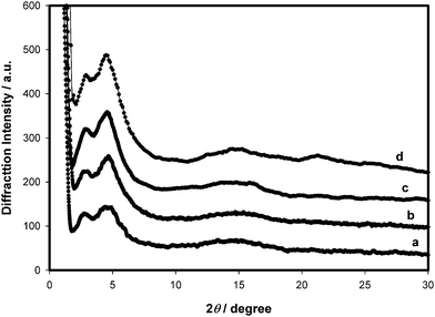 | ||
| Fig. 6 XRD patterns of P3HT : PCBM before (a) and after (b) thermal annealing at 150 °C for 2 h and the graft copolymer 8d before (c) and after (d) thermal annealing, on quartz substrates. | ||
In addition, a peak at 2θ = 2.8° is observed (d-spacing, ∼30 Å) which may be attributed to a longer interchain distance caused by the presence of the fullerenes sandwiched between copolymer backbones. For films of P3HT:PCBM blend, developed under similar conditions, this peak is observable too. We therefore conclude that the slow drying provides enough time for the covalently linked fullerene to fill the gap in between the stacked PT backbones thus forcing them to adopt longer d-spacing (30 Å) in addition to the usual one (16–20 Å). Furthermore, the fact that crystallinity is not affected by thermal annealing is convincingly in agreement with the TEM results discussed above.
Hole mobilities
Hole mobilities of selected graft polymers were measured by the space–charge limited current (SCLC) technique. The SCLC model predicts a quadratic variation of the current density with applied voltage, J = (9/8)εε°(V2/L3)µ, where J is the current density, ε the relative permittivity of the medium, ε° the permittivity of vacuum, V the potential, L is the active layer thickness, and µ is the hole mobility. Evidence for the SCLC condition is provided for a representative double log plot of the J–V curves which illustrates the transition from ohmic to trap-controlled current to SCLC behavior (Figure S18†).25 Log J–log V plots exhibited a slope of 2 at higher voltage consistent that the SCLC region was obtained, as shown in Figure S18†. A larger voltage was required to reach the space–charge limited region for the fullerene-graft copolymers, compared to the pure P3HT film, which is evidence of a higher resistivity to hole transport. SCLC hole mobilities are plotted in Fig. 7 as a function of active layer thickness and % post-functionalization of P3HT, i.e., graft-chain density. A striking feature is that for C60- and PCBM-graft copolymers, the hole mobilities are several orders of magnitude lower than pure P3HT (RR > 98%; 1.9 × 10⁻⁴ cm2 V−1 s−1). Reducing the graft-chain density by lowering the degree of post-functionalization improved the hole mobility from 2.6 × 10⁻⁹ (8e) to 7.2 × 10⁻⁶ cm2 V−1 s−1 (8a) for an active layer thickness of 70 nm. A similar trend was observed for the C60-graft copolymers: the hole mobility increased from 1.0 × 10⁻¹⁰ for the 20 mol% post-functionalized C60-graft copolymer, 7d to 5.4 × 10⁻⁸ cm2 V−1 s−1 for 7b. Despite the nearly three orders of magnitude improvement in hole mobility the data indicate that the fullerene-graft copolymers investigated are much poorer hole conductors than the original P3HT from which they came. The hole mobility shows a thickness dependence: the thicker the active layer, the higher the mobility—this is consistent with that reported for low Mw P3HT in which field-effect hole mobilities increased from 10−7 to 10−6 with increasing thickness as a result of an evolving morphology.26 While this may explain the increase in mobility in the present studies the point is simply made that hole mobility is strongly dependent on the density of graft chains.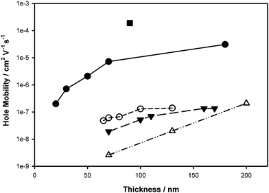 | ||
| Fig. 7 Hole mobility for the graft copolymers 8a (●), 8b (○), 8c (▼), 8e (△) and P3HT (■) as a function of thickness. | ||
Photovoltaic properties
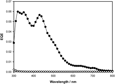
PV devices based on fullerene-bearing graft copolymers were fabricated and characterized in order to provide further clarification of their opto-electronic properties. For comparison, PV devices of the P3HT–PCBM blends (1 : 1 wt% ratio) were also fabricated. Under simulated solar irradiation (100 mW cm−2, AM1.5G filter), standard P3HT–PCBM blend devices exhibited power conversion efficiencies (PCE) ranging from 1.2–3.3%. For the highest device performance of 3.3%, the short-circuit current density (Jsc), open-circuit potential (Voc) and fill-factor (FF) were 10 mA cm−2, 0.57 V and 0.58, respectively. The external quantum efficiency (EQE) shows a maximum value of 0.6 at 500–550 nm with a shoulder extended to 650 nm. In contrast, PV devices in which fullerene-graft copolymers were used as the active layer gave power conversion efficiencies in the range 10−5 to 0.04%. The J–V characteristic and plots of EQE for the graft copolymer, 7b, are shown in Fig. 8. For this device the obtained PV parameters are: Jsc = 4.6 × 10⁻³ mA cm−2, Voc = 0.46 V, FF = 0.24, and PCE = 0.04%. The relatively poor FF is attributed to a large series resistance, which was also observed in SCLC measurements. The plot of EQE vs. incident wavelength exhibits peaks at 330 and 430 nm due to absorption by PCBM graft chains and P3HT main chain. The high resistivity is a common feature in these fullerene-graft copolymers, irrespective of the graft-chain density and the fullerene type, and results from poor charge carrier mobility, which in turn is due to a lower degree of crystallinity in the solid state. However, as shown in Table 5, the PCE of PV devices increases upon lowering the degree of post-functionalization of P3HT; on traversing the series from 8e to 8a and 7e to 7b, the PCEs increased from 6.0 × 10⁻⁵ to 1.2 × 10⁻³ and 6.6 × 10⁻⁵ to 0.04%, respectively.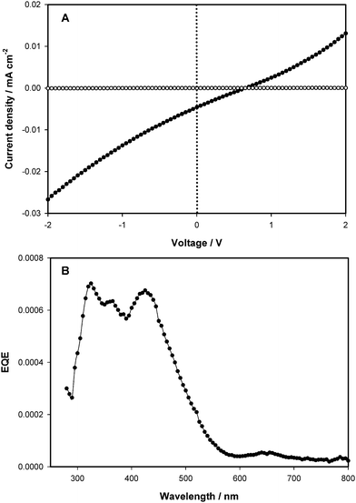 | ||
| Fig. 8 J–V characteristic (A); dark current (○), photocurrent (●) and EQE (B) for the graft copolymer 7b. | ||
An important consideration that plays a strong role in PV device performance is the absolute and relative mass contents of P3HT and fullerene in the active layer. The P3HT content in the graft copolymers 7b–d and 8b–d is estimated to range from 13 to 20 wt% (Table 2) which is much lower than the P3HT content in molecular P3HT:PCBM blend (50 : 50 wt%) used in high performance BHJ devices. The fullerene content in the graft copolymers is calculated to be 20–41 wt% which is also lower than optimized BHJ devices. The active components are diluted by 36 to 60 wt% of the PV inactive component, i.e., poly(CMS-stat-ST) side chains.
The graft copolymers described above clearly contained a lower content of photoactive material compared to state-of-the-art BHJ devices. Given that BHJ devices often contain a higher proportion of fullerene, PCBM was added to the casting solutions to determine if this would increase the charge generation/carrier properties and improve PV device performance. PCEs for the graft copolymers containing additional PCBM in a 1 : 1 graft copolymer : PCBM mass ratio are shown in Table 5. The addition of PCBM to the graft copolymer improves their photoconversion efficiency. Fig. 9 compares action spectra of the devices prepared with graft copolymer 8d and its 1 : 1 PCBM blend, for which the PCEs are 2.4 × 10⁻⁴ and 0.046%, respectively. In the case of 8d, the P3HT to ST/CMS to fullerene mass ratio is estimated to be 14 : 60 : 26. In the 1 : 1 blend of graft copolymer : PCBM the composition is 7 : 30 : 63. The active component (P3HT + PCBM) constitutes 70% of the total mass. Addition of PCBM contributes to the PCE improvement, first, by increasing the microscopic donor–acceptor interface, and second, by developing a more efficient and bi-continuous interpenetrating network. However, P3HT constitutes only 7% of mass, which is much lower than state-of-the-art devices, and is believed to be the main cause for low overall performance.
 | ||
| Fig. 9 EQE of 8d (○) and its 1 : 1 blend with PCBM (●). | ||
The low P3HT content in the graft copolymers is an important factor in defining properties such as hole mobility and PCE of PV devices. As shown in Fig. 7, the hole mobility for the PCBM (8a–d) and C60 (7b–d) graft copolymers correlates with the extent of post-functionality. The sharp decline in hole mobility upon even 1 mol% functionalization can be explained partially on the basis that the P3HT content in the graft copolymer 8a constitutes 44 wt% of P3HT, the remaining 56 wt% is a “hole insulator”, thus the hole mobility drops several orders of magnitude.
The presence of the side chains bearing bulky fullerene molecules clearly influences the π–π stacking of the thiophene rings. As a result, fullerene-functionalized copolymers experience severe distortion of the main chain and reduced crystallinity of the P3HT domains. These factors are the most likely cause for their poor hole mobility and sub-par PV performance, rather than a simple lowering of the P3HT content in the active layer.
Conclusion
A series of donor–acceptor graft copolymers based on P3HT as the donor moiety and the C60 or PCBM as acceptors has been synthesized through cycloaddition of fullerene acceptor moieties onto an azido substituted CMS/ST side chain grown on the thiophene backbone. The synthetic methodology enables covalent attachment of the fullerene to side chains grown onto P3HT. The use of PCBM improved the solubility of the fullerene-graft copolymers, and minimized their aggregation in solution, which was observed for C60-graft copolymers. Replacement of C60 with PCBM enabled quantitative characterization of fullerene content by NMR spectroscopy. This analysis confirmed that TGA methods are useful for estimations of fullerene content.Graft copolymers were characterized using a variety of methods. NMR and TGA analyses indicated that 20–41 wt% grafting of the fullerene was achieved, depending on the side chain length, the initial CMS : ST feed ratio, and graft density. PV devices based on these materials exhibited very low figures of merit. Hole mobilities (10−10–10−5 cm2 V−1 s−1) for the graft copolymers were much smaller than for P3HT (1.9 × 10⁻⁴ cm2 V−1 s−1), and are direct cause for the poor PV performance.
A morphological study revealed the graft copolymers form a binary network of the donor and acceptor domains and possess feature sizes of ∼5 nm and less, which is smaller than molecular films of P3HT and PCBM. The bi-continuous morphology provides a large interfacial area between the donor backbone and fullerene and the efficiency of electron-hole formation is evident by the efficient quenching of PL but this does not necessarily lead to enhanced PV activity. On the contrary, it appears that too small a nanostructure reduces PV activity—because the degree of crystallinity of P3HT in the nano-sized domains is much lower than in pristine P3HT. It appears aggregation of the less soluble fullerene group during film formation restricts its self-organization of the conjugated polymer—thus reducing its domain size, lowering crystallinity, charge mobility, and PV activity. An additional conclusion of this work is that morphology and feature size is maintained even after extended annealing, thus demonstrating the ability of graft structures to stabilize nanoscale morphologies.
Acknowledgements
Authors gratefully acknowledge funding from NSERC and SFU.Notes and references
- (a) S. A. Jenekhe and X. L. Chen, Science, 1998, 279, 1903–1907 CrossRef CAS; (b) H. A. Klok and S. Lecommandoux, Adv. Mater., 2001, 13, 1217–1229 CrossRef CAS; (c) S. Gunes, H. Neugebauer and N. S. Sariciftci, Chem. Rev., 2007, 107, 1324–1338 CrossRef.
- (a) K. Sivula, C. K. Luscombe, B. C. Thompson and J. M. J. Fréchet, J. Am. Chem. Soc., 2006, 128, 13988–13989 CrossRef CAS; (b) W. L. Ma, C. Y. Yang, X. Gong, K. Lee and A. J. Heeger, Adv. Funct. Mater., 2005, 15, 1617–1622 CrossRef CAS; (c) G. Li, V. Shortriya, J. S. Huang, Y. Yao, T. Moriarty, K. Emery and Y. Yang, Nat. Mater., 2005, 4, 864–868 CAS; (d) M. Reyes-Reyes, K. Kim and D. L. Carroll, Appl. Phys. Lett., 2005, 87, 203113 CrossRef; (e) T. Nishizawa, K. Tajima and K. Hashimoto, J. Mater. Chem., 2007, 23, 2440–2445 Search PubMed.
- F. Yang and S. R. Forrest, ACS Nano, 2008, 2, 1022–1032 CrossRef CAS.
- (a) M. Campoy-Quiles, T. Ferenczi, T. Agostinelli, P. G. Etchegoin, Y. Kim, T. D. Anthopoulos, P. N. Stavrinou, D. D. C. Bradley and J. Nelson, Nature, 2008, 7, 158–164 CrossRef CAS; (b) H. Hoppe and N. S. Sariciftci, J. Mater. Chem., 2006, 16, 45–61 RSC; (c) X. Yang and J. Loos, Macromolecules, 2007, 40, 1353–1362 CrossRef CAS.
- K. Sivula, Z. T. Ball, N. Watanabe and J. M. J. Fréchet, Adv. Mater., 2006, 18, 206–210 CrossRef CAS.
- C. H. Woo, B. C. Thompson, B. J. Kim, M. F. Toney and J. M. J. Fréchet, J. Am. Chem. Soc., 2008, 130, 16324–16329 CrossRef CAS.
- M. Jørgensen, K. Norrman and F. C. Krebs, Sol. Energy Mater. Sol. Cells, 2008, 92, 686–714 CrossRef.
- (a) T. M. Figueira-Duarte, A. Gégout and J. F. Nierengarten, Chem. Commun., 2007, 109–119 RSC; (b) T. Nishimura, S. Takatani, S. Sakurai, K. Maeda and E. Yashima, Angew. Chem., Int. Ed., 2002, 41, 3602–3604 CrossRef CAS; (c) A. Cravino and N. S. Sariciftci, J. Mater. Chem., 2002, 12, 1931–1943 RSC; (d) U. Stalmach, B. de Boer, C. Videlot, P. F. van Hutten and G. Hadziioannou, J. Am. Chem. Soc., 2000, 122, 5464–5472 CrossRef CAS; (e) B. de Boer, U. Stalmach, P. F. van Hutten, C. Meltzer, V. V. Krasnikov and G. Hadziioannou, Polymer, 2001, 42, 9097–9109 CrossRef CAS; (f) S. M. Lindner, S. Hüttner, A. Chiche, M. Thelakkat and G. Krausch, Angew. Chem., Int. Ed., 2006, 45, 3364–3368 CrossRef CAS; (g) S. M. Lindner and M. Thelakkat, Macromolecules, 2004, 37, 8832–8835 CrossRef CAS; (h) S. S. Sun, Sol. Energy Mater. Sol. Cells, 2003, 79, 257–264 CrossRef CAS; (i) J. U. Lee, A. Cirpan, T. Emrick, T. P. Russell and W. H. Jo, J. Mater. Chem., 2009, 19, 1483–1489 RSC.
- M. H. van der Veen, B. de Boer, U. Stalmach, K. I. van der Wetering and G. Hadziioannou, Macromolecules, 2004, 37, 3673–3684 CrossRef CAS.
- S. Barrau, T. Heiser, F. Richard, C. Brochon, C. Ngov, K. van de Wetering, G. Hadziioannou, D. V. Anokhin and D. A. Ivanov, Macromolecules, 2008, 41, 2701–2710 CrossRef CAS.
- Z. Tan, J. Hou, Y. He, E. Zhou, C. Yang and Y. Li, Macromolecules, 2007, 40, 1868–1873 CrossRef CAS.
- (a) X. Chen, B. Gholamkhass, X. Han, G. Vamvounis and S. Holdcroft, Macromol. Rapid Commun., 2007, 28, 1792–1797 CrossRef CAS; (b) Y. Li, G. Vamvounis and S. Holdcroft, Macromolecules, 2001, 34, 3130–3132 CrossRef CAS; (c) Y. Li, G. Vamvounis and S. Holdcroft, Macromolecules, 2001, 34, 142–143; (d) Y. Li, G. Vamvounis and S. Holdcroft, Macromolecules, 2002, 35, 6900–6906 CrossRef CAS.
- C. J. Hawker, A. W. Bosman and E. Harth, Chem. Rev., 2001, 101, 3661–3688 CrossRef CAS.
- J. Roncali, Chem. Rev., 1992, 92, 711–738 CrossRef CAS.
- (a) H. Fang, S. Wang, S. Xiao, Y. Li, Z. Shi, C. Du, Y. Zhou and D. Zhu, Macromol. Chem. Phys., 2002, 203, 1931–1935 CrossRef CAS; (b) S. Xiao, S. Wang, H. Fang, Y. Li, Z. Shi, C. Du and D. Zhu, Macromol. Rapid Commun., 2001, 22, 1313–1318 CrossRef CAS.
- (a) M. Prato, J. Mater. Chem., 1997, 7, 1097–1109 RSC; (b) Y. Li, Z. Mao, J. Xu, J. Yang, Z. Guo, J. Li and B. Yin, Chem. Phys. Lett., 1997, 265, 361–364 CrossRef CAS.
- C. Mathis, B. Schmaltz and M. Brinkmann, C. R. Chim., 2006, 9, 1075–1084 CrossRef CAS.
- R. S. Loewe, P. C. Ewbank, J. Liu, L. Zhai and R. D. McCullough, Macromolecules, 2001, 34, 4324–4333 CrossRef CAS.
- (a) T. Heiser, G. Adamopoulos, M. Brinkmann, U. Giovanella, S. Ould-Saad, C. Brochon, K. I. van der Wetering and G. Hadziioannou, Thin Solid Films, 2006, 511, 219–223 CrossRef; (b) K. I. van der Wetering, C. Brochon, C. Ngov and G. Hadziioannou, Macromolecules, 2006, 39, 4289–4297 CrossRef.
- F. Ouhib, A. Khoukh, J.-B. Ledeuil, H. Martinez, J. Desbriéres and C. Dagron-Lartigau, Macromolecules, 2008, 41, 9736–9743 CrossRef CAS.
- C. Winder and N. S. Sariciftci, J. Mater. Chem., 2004, 14, 1077–1086 RSC.
- (a) J. Peet, J. Y. Kim, N. E. Coates, W. L. Ma, D. Moses, A. J. Heeger and G. C. Bazan, Nat. Mater., 2007, 6, 497–500 CrossRef CAS; (b) J. K. Lee, W. L. Ma, C. J. Brabec, J. Yuen, J. S. Moon, J. Y. Kim, K. Lee, G. C. Bazan and A. J. Heeger, J. Am. Chem. Soc., 2008, 130, 3619–3623 CrossRef CAS.
- (a) S. Cook, R. Katoh and A. Furube, J. Phys. Chem. C, 2009, 113, 2547–2552 CrossRef CAS; (b) I.-W. Hwang, D. Moses and A. J. Heeger, J. Phys. Chem. C, 2008, 112, 4350–4354 CrossRef CAS; (c) F. Guo, K. Ogawa, Y.-G. Kim, E. O. Danilov, F. N. Castellano, J. R. Reynolds and K. S. Schanze, Phys. Chem. Chem. Phys., 2007, 9, 2724–2734 RSC.
- P. E. Shaw, A. Ruseckas and I. D. W. Samuel, Adv. Mater., 2008, 20, 3516–3520 CrossRef CAS.
- Z. Chiguvare, J. Parisi and V. Dykonov, J. Appl. Phys., 2003, 94, 2440–2448 CrossRef CAS.
- S. Joshi, S. Grigorian, U. Pietsch, P. Pingel, A. Zen, D. Neher and U. Scherf, Macromolecules, 2008, 41, 6800–6808 CrossRef CAS.
Footnote |
| † Electronic supplementary information (ESI) available: Detailed synthesis, NMR, UV-Vis, FTIR, PL spectra, XRD, TGA and TEM images. See DOI: 10.1039/b9py00384c |
| This journal is © The Royal Society of Chemistry 2010 |