Synthesis and photoluminescence of Eu3+-activated double perovskite NaGdMg(W, Mo)O6 – a potential red phosphor for solid state lighting†
Le
Zhang
,
Zhou
Lu
,
Pengde
Han
,
Lixi
Wang
and
Qitu
Zhang
*
College of Materials Science and Engineering, Nanjing University of Technology, 5 Xinmofan Road, Nanjing, Jiangsu, P.R. China. E-mail: njutzl@163.com; Tel: +86-25-83587246
First published on 18th October 2012
Abstract
A novel high-efficiency double perovskite NaGdMg(W, Mo)O6:Eu phosphor is obtained by an improved citrate–EDTA complexing method. An emission intensity over twenty times that of a commercial red phosphor is observed. The host material has high-efficiency absorption, high doping concentration for many rare earth ions and intense emission with different colors.
Phosphor-converted white light emitting diodes (LEDs) are regarded as a new lighting source for the next generation.1–3 The present technical bottleneck is that the as-resulted white light is cool, which lacks color richness. The white LEDs demand red phosphors excited by blue or near ultraviolet (NUV) LED chips.4,5 However, the red phosphors of sulfides or nitrides suffer from poor chemical stability or need rigorous synthesis conditions. Therefore, it is very urgent to develop the chemically stable, environmentally friendly and high-efficiency oxide phosphors to meet the requirements for solid state lighting.6–8
Recently, many studies have shown that the double perovskite structure host A2BMO6 (A = Sr, Ba; B = Ca, Mg; M = W, Mo) could effectively transfer energy to the activator ions (Eu3+) and then generate intense red emission.9–14 However, the dominant transition of Eu3+ ions in this lattice is 5D0 → 7F1 (594 nm). Another 5D0 → 7F2 transition (615 nm) is forbidden due to the high symmetry of the doped site, generating the orange-red emission but not pure red light. Therefore, studying how to lower the symmetry of doped site and alter the dominant transition of Eu3+is very interesting, as well as further enhancing the luminescence intensity. Here, a novel double perovskite NaGdMgWO6 was first selected as the host to obtain the electric–dipole transition (615 nm) of Eu3+ due to the lower symmetry of A-site. But as it is well known, the charge transfer band (CTB) of WO6 is at about 325 nm and very weak. It is so far from the emission wavelength of NUV LED (∼390 nm). Predictably, a great luminescence enhancement of Eu3+ will occur if CTB shifts to the NUV region.
Generally, MoO6 is used to substitute WO6 to tune the CTB of the tungstate host because of the isomorphism effect. However, the double perovskite NaGdMgWO6 has a special lattice arrangement: long-range ordering of B-site cations (Mg/W) in a rock-salt fashion and layered ordering of A-site cations (Na/Gd) in an AA′BB′O6 lattice.15 And layered ordering of A-site cations creates a bonding instability that is compensated for by a second-order Jahn–Teller (SOJT) distortion of B′ cations. These two distortions are synergistic and the removal of one leads to the disappearance of the other one. Therefore, Mo and W cannot be coexistent in this lattice maybe due to the stronger SOJT distortion of Mo6+ in octahedral-coordination than that of W6+, or the resulting severe distortion will lead to damage of the perovskite structure and the corresponding molybdate will be formed preferentially, which has been proved by many attempts using solid-state reaction method even at high calcination temperature and long holding time.
However, in this communication, what's exciting is that Mo and W elements are coexistent in NaGdMgWO6 lattice with simultaneous ordering of A and B-site cations using an improved citrate–EDTA complexing method. The CTB of NaGdMgWO6 is successfully shifted to the NUV region and the composition-optimized phosphor exhibits excellent emission characteristic and dramatically enhanced red emission.
The special part of this preparation method first used to synthesize double perovskite powders was that the addition of different metal ions and complexing agents should follow the designed order and the pH values of the mixed solution at every step should be accurately controlled. The detailed experimental process and equipment used are provided in the ESI†.
The powder XRD patterns (Fig. 1) of NaGdMg(W1−xMox)O6:Eu3+ powders (x ≤ 0.5) showed that they matched well with the pure double perovskite structure NaGdMgWO6. The superlattice diffraction peaks at 19.62° (011) and 38.15° (211) indicated long-range ordering of B-site cations in a rock-salt fashion. The appearance of 11.22° (001) and 25.43° (111) peaks demonstrated the layered ordering of A-site cations.16 A schematic diagram of the simulated lattice is shown in Fig. 2(a). In fact, the pure AA′MgMoO6 compound does not exist, even though many attempts have been made to produce it, including increasing the calcination temperature and changing the combination of A + A′ cations (Fig. S1†). The very severe distortion leads to damage of the perovskite structure with increasing the Mo content. In our experiments, the samples have not kept the double perovskite structure when x > 0.5, and Gd2MoO6 was formed preferentially. Maybe a high-pressure is needed for the transition from Gd2MoO6 to double perovskite because of the increased coordination numbers of Mo and Na.
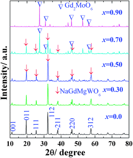 | ||
| Fig. 1 XRD patterns of NaGdMg(W1−xMox)O6 powders. | ||
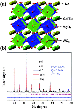 | ||
| Fig. 2 (a) A schematic crystal structure of NaGdMgWO6, (b) observed (cross), calculated (solid line) and difference (bottom) results of XRD refinement of NaGdMg(W0.5Mo0.5)O6. | ||
The XRD refinement of NaGdMg(W0.5Mo0.5)O6:Eu0.1 is shown in Fig. 2(b). This crystal is a monoclinic structure with space group of P21 and lattice parameters of a = 5.3817(1) Å, b = 5.4882(1) Å, c = 7.8219(2) Å and β = 90.452(1)°. Mo atoms uniformly substituted W atoms at 4i site. All the observed peaks satisfied reflection conditions, wRp = 6.37%, Rp = 5.14% and χ2 = 1.96 and the refined composition determined by ICP-OES was Na1.00(2)Gd0.907(1)Eu0.104(4)Mg0.995(5)W0.510(1)Mo0.493(2). These results indicate MoO6 can also exist in the AA′MgWO6 lattice with a big distortion with the help of WO6, which is significant for the CTB adjustment of NaGdMgWO6.
The diffuse reflection spectra of Na(Gd0.9Eu0.1)Mg(W1−xMox)O6 and excitation spectra monitored the 5D0–7F2 transition (615 nm) are shown in Fig. 3. With the increase of Mo content, the CTB gradually shifted to the long wavelength and reached 386 nm at x = 0.5 but then shifted back when x > 0.5 due to the damage of perovskite structure. Their excitation spectra exhibited similar change with the enhanced absorption in NUV and blue regions (465 nm). Their emission spectra (λex = 395 nm) are shown in Fig. 4(a). The luminescence intensity of 5D0–7F2 reached the maximum when x = 0.5.
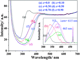 | ||
| Fig. 3 Diffuse reflection spectra and excitation spectra (λem = 615 nm, inset) of Na(Gd0.9Eu0.1)Mg(W1−xMox)O6 phosphors. | ||
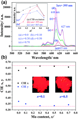 | ||
| Fig. 4 (a) Emission spectra of Na(Gd0.9Eu0.1)Mg(W1−xMox)O6 phosphors and intensity variation of 5D0–7F2 transition under different excitation wavelengths and (b) their color coordinates and body images under a 365 nm UV lamp. | ||
In double perovskite NaGdMgWO6, the three-dimensional arrangement of WO6 is separated by MgO6. The replacement of W with Mo increases the distance between WO6 and enlarges the electron delocalization of WO6.17 In addition, the electronegativity of Mo (2.16) is lower than that of W (2.36). This enlarges the electron-cloud overlap between center cations (W/Mo6+) and their coordination anion (O2−).18 The charge transfer from O to W/Mo easily occurs due to the decrease of energy gap. A lower excitation energy will lead to the charge transfer occur. Therefore, the red shift of CTB was observed. Meanwhile, when the distance between WO6 is short, almost all absorbed energy from WO6 is quenched in the transferring process along (MgW)O6 framework and only a little energy is trapped by Eu3+. With increasing Mo content, the distance between WO6 gets longer and the energy transition is blocked by MoO6. These result in more energy transferred to Eu3+. In addition, the gap of emission intensity between λex = 465 nm and λex = 395 nm gradually decreased with the increase of Mo content (Fig. 4(a), inset), which indicated this phosphor could be applied for NUV and blue LED chips with almost similar intensity.
In addition, an unusual phenomenon is very interesting. The dominated transition of 5D0–7F2 at 615 nm (x ≤ 0.1) split into double peaks at 610 and 627 nm (x > 0.1) with increased full width at half maximum. This broadening and split of 5D0–7F2 transition is rarely found, especially with the increase of Mo content. As we know, 5D0–7F2 of Eu3+ is an electric dipole transition strongly affected by the crystal symmetry. This split indicates that Eu3+ occupies a site with lower symmetry, which may be due to the big SOJT distortion of Mo6+. It is believed that the degree of SOJT distortion would affect the luminescence of Eu3+ and more detailed work will be carried out. The present broadening and split will greatly enhance the purity of red light. The corresponding CIE coordinates (Fig. 4(b)) are about (0.666, 0.334) when x = 0.3–0.5, which is very close to the standard NTSC (0.670, 0.330) and this phosphor is considered either to be used for NUV LEDs or to compensate the red deficiency of YAG:Ce.
Meanwhile, the layered ordering of A-site cations means a double distance between the RE3+ ions in neighboring layers. And in one layer, the neighboring RE3+ ions are also separated by BO6 octahedrons. This special double perovskite structure leads to a longer distance between activator ions. Thus, the quenching concentration may be delayed or disappear for many different RE3+ ions. In fact, the optimum doping concentration of Eu3+ reached 50.0 mol% and such a high doping concentration guaranteed high luminescence. Fig. 5 shows the emission comparison of NaGdMg(W0.5Mo0.5)O6:Eu0.5, commercial Y2O2S:Eu0.05 (Changshu YaTai, Jiang Su, China) and CaMoO4:Eu0.3 phosphors. The highest and reddest emission was observed from the double perovskite phosphor and it was over twenty and six times, respectively, stronger than that of another two phosphors. The quantum yields of phosphors at different excited wavelength were determined and listed in Fig. 5. The quantum yield of NaGdMg(W0.5Mo0.5)O6 (λex = 395 nm) was about 58.4%. However, the improvement of the quantum yield (4–15 times) is a little lower than the luminescence intensity (twenty times). This is mainly induced by the technical details, such as the scattering, and the particles size, which influence the interaction of samples with the incident light to induce different absorption and reflection.
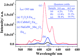 | ||
| Fig. 5 Photoluminescence comparison of three phosphors: (a) Y2O2S:Eu0.05; (b) CaMoO4:Eu0.3; (c) NaGdMg(W0.5Mo0.5)O6:Eu0.5. | ||
Further work on other RE3+ ion doped NaGdMg(W, Mo)6 powders is shown in Fig. 6. The concentration-optimized NaGdMg(W0.5Mo0.5)O6:Tb0.4/Eu0.5/Dy0.3 powders emit intense green, red and almost pure white light, respectively, which demonstrate this excellent host material has great potential in solid state lighting.
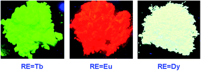 | ||
| Fig. 6 The photos of NaGdMg(W0.5Mo0.5)O6:Tb0.4/Eu0.5/Dy0.3 phosphors under a 365 nm UV lamp. | ||
This work was financially supported by the Priority Academic Program Development of Jiangsu Higher Education Institutions (PAPD), National Natural Science Foundation of China (51202111) and Research and Innovation Program for College Graduates of Jiangsu Province (CXZZ12_0410).
Notes and references
- C. C. Lin and R. S. Liu, J. Phys. Chem. Lett., 2011, 2, 1268 CrossRef CAS.
- S. Ye, F. Xiao, Y. X. Pan, Y. Y. Ma and Q. Y. Zhang, Mater. Sci. Eng., R, 2010, 71, 1 CrossRef.
- C. Sommer, P. Hartmann, P. Pachler, H. Hoschopf and F. P. Wenzl, J. Alloys Compd., 2012, 520, 146 CrossRef CAS.
- H. Nersisyan, H. I. Won and C. W. Won, Chem. Commun., 2011, 47, 11897 RSC.
- Q. T. Zhang, L. Zhang, P. D. Han, Y. Chen, H. Yang and L. X. Wang, Prog. Chem., 2011, 23, 1108 CAS.
- Y. Chen, J. Wang, C. Liu, X. Kuang and Q. Su, Appl. Phys. Lett., 2011, 98, 081917 CrossRef.
- A. Kumar and J. Kumar, J. Mater. Chem., 2011, 21, 3788 RSC.
- Q. L. Dai, M. E. Foley, C. J. Breshike, A. Lita and G. F. Strouse, J. Am. Chem. Soc., 2011, 133, 15475 CrossRef CAS.
- V. Sivakumar and U. V. Varadaraju, Electrochem. Solid-State Lett., 2006, 9, H35 CrossRef CAS.
- F. Lei and B. Yan, J. Optoelectron. Adv. Mater., 2008, 10, 158 CAS.
- V. Sivakumar and U. V. Varadaraju, J. Solid State Chem., 2008, 181, 3344 CrossRef CAS.
- S. Ye, C. H. Wang and X. P. Jing, J. Electrochem. Soc., 2008, 155, J148 CrossRef CAS.
- S. Ye, C. H. Wang, Z. S. Liu, J. Lu and X. P. Jing, Appl. Phys. B: Lasers Opt., 2008, 91, 551 CrossRef CAS.
- J. Hou, X. Yin, F. Huang and W. Jiang, Mater. Res. Bull., 2012, 47, 1295 CrossRef CAS.
- G. King, S. Thimmaiah, A. Dwivedi and P. M. Woodward, Chem. Mater., 2007, 19, 6451 CrossRef CAS.
- C. G. King, L. M. Wayman and P. M. Woodward, J. Solid State Chem., 2009, 182, 1319 CrossRef.
- K. M. Ok, P. S. Halasyamani, D. Casanova, M. Llunell, P. Alemany and S. Alvarez, Chem. Mater., 2006, 18, 3176 CrossRef CAS.
- C. K. Jørgensen, Mol. Phys., 1962, 5, 271 CrossRef.
Footnote |
| † Electronic supplementary information (ESI) available: Experimental, characterization of samples, Fig. S1. See DOI: 10.1039/c2tc00189f |
| This journal is © The Royal Society of Chemistry 2013 |