
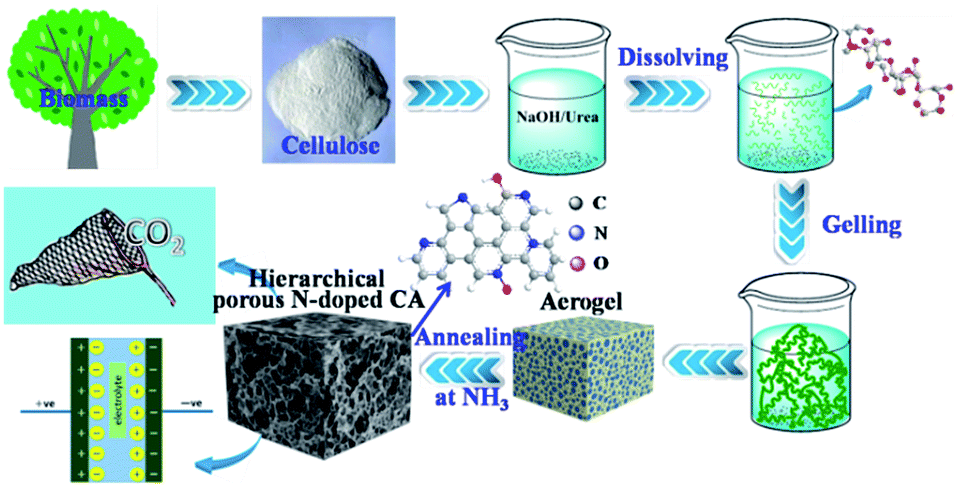
3D hierarchical porous N-doped carbon aerogel from renewable cellulose: an attractive carbon for high-performance supercapacitor electrodes and CO2 adsorption
Yijie Hua,
Xing Tonga,
Hao Zhuoa,
Linxin Zhong*a,
Xinwen Peng*a,
Sha Wanga and
Runcang Sunab
aState Key Laboratory of Pulp and Paper Engineering, South China University of Technology, Guangzhou, P. R. China. E-mail: lxzhong0611@scut.edu.cn; fexwpeng@scut.edu.cn
bBeijing Key Laboratory of Lignocellulosic Chemistry, Beijing Forestry University, Beijing, China. E-mail: rcsun3@bjfu.edu.cn
First published on 1st February 2016
Abstract
Hierarchical porous N-doped carbons have attracted great interest in energy storage and CO2 capture applications due to their unique porous structure and physicochemical properties. Fabrication of cost-effective and eco-friendly hierarchical porous N-doped carbons from renewable biomass resources is a sustainable route for future energy storage. However, it is still a big challenge to produce N-doped carbons with hierarchical porous structure from cellulose, which is the most abundant and widely available renewable resource on earth. Here, we designed a facile and effective strategy to produce hierarchical porous N-doped carbons from cellulose for high-performance supercapacitor and CO2 capture applications. In this method, hierarchical porous cellulose aerogels were first obtained via a dissolving–gelling process and then carbonized in NH3 atmosphere to give hierarchical porous N-doped carbon aerogels with more interconnected macropores and micropores. Due to the unique porous structure and physicochemical properties, the as-prepared N-doped carbon aerogels had a high specific capacitance of 225 F g−1 (0.5 A g−1) and an outstanding cycling stability. For the first time, we also demonstrated that this N-doped carbon aerogel exhibited a exceptional CO2 adsorption capacity of 4.99 mmol g−1, which is much higher than those of other porous carbons. This novel hierarchical porous N-doped carbon has great potential applications in CO2 capture, energy storage, porous supports, and electrochemical catalysis.
Introduction
Porous carbons have excellent physical and chemical properties such as high specific surface area, high electrical conductivity, excellent stability, low cost, and long cycling life, and thus are extremely important for supercapacitors.1,2 Various carbon materials, including activated carbon,3,4 carbon aerogels,5,6 carbon nanotubes,7 and graphene,8,9 have exhibited high performances for supercapacitors and have attracted extensive attention. However, conventional porous carbons, which are mainly derive from fossil resources, face many problems due to the depletion of fossil resources in the near future, thus seriously limiting their future applications. Renewable biomass, which is the most abundant carbon source on the earth, is low-cost, and environmentally friendly resource and represents a sustainable way for fabricating porous carbons. Recently, much attention has been focused on using various biomass resources to fabricate carbonaceous materials for supercapacitor applications, such as chitosan,10,11 lignin,12,13 gelatin,14,15 cellulose,16,17 and so on.18,19 These materials have excellent supercapacitance performances that are comparable to those of conventional petroleum-based carbon materials.20,21 Among various biomass resources, polysaccharide cellulose composed of C, H, and O is the most abundant and widely available biopolymer in nature, and it can provide a sustainable carbon resource for energy storage. Up to now, however, fabricating porous carbons from cellulose for high-performance supercapacitor application is challenging due to the compact structure of cellulose fiber. Wang et al.17 prepared partially graphitic carbon nanosheets with a high specific surface area (up to 2287 m2 g−1) and a capacitance of about 124 F g−1 (0.5 A g−1) from hemp bast fiber. Luo et al.22 synthesized a nanoporous carbon membrane with a specific capacitances of 120 F g−1 (0.5 A g−1) from cellulose filter paper. However, these cellulose-based carbon materials mentioned above were obtained by directly carbonizing and activating the compact cellulose fiber, high specific surface area resulting from numerous mesopores and micropores (developed during chemical activation) did not significantly contribute to high specific capacitance.The ideal supercapacitor electrode materials should have a hierarchical porous structure (multi-scale pores) containing macropores for the ion-buffering reservoir, mesopores for ion transportation, and micropores for the enhancement of charge storage.23 Since cellulose can be dissolved in several solvents and then easily form a gel in an anti-solvent due to the aggregation of cellulose chains (as a result of large amounts of hydrogen bonds formed between cellulose chains), a 3D hierarchical porous aerogel and carbon aerogel can be obtained by freeze-drying or supercritical CO2 drying and subsequent carbonization, respectively. The carbon aerogel inherits the hierarchical structure of the cellulose aerogel. This dissolving and gelling process not only destroys the compact structure of cellulose fiber, but also reconstructs a hierarchical porous architecture. However, to the best of our knowledge, the only report on the synthesis of cellulose-based carbon aerogel for supercapacitor application is by Hao and coworkers.24 They fabricated a highly porous carbon aerogel from bagasse cellulose by dissolving, gelling, pyrolysis, and then chemical activation. The carbon aerogel showed a specific capacitance of 142.1 F g−1 (0.5 A g−1).
It is well known that nitrogen doping can introduce electrocatalytic active sites, enhance the electrical conductivity and surface hydrophilicity to facilitate charge-transfer and electrolyte–electrode interactions, respectively.25,26 N-Doped carbonaceous materials have raised increasing interest due to their improved properties in electronics,27 catalysis,28,29 CO2 adsorption,30 batteries,31 and electrical double-layer capacitors.32 The high capacitance of N-doped carbon materials is primarily due to the modification of the electronic structure of graphene.33 For example, the area-normalized capacitance increased from 6 mF cm−2 for the activated graphene to 22 mF cm−2 for the N-doped activated graphene with 2.3% N-doping content.33 Zhao et al.34 demonstrated that the specific capacitance of N-doped graphene framework was significantly improved compared with the N-free one. However, to the best of our knowledge, the only report on the synthesis of N-doped carbon from cellulose was by Luo22 and Wang.35 In Luo's study, an N-doped carbon membrane was obtained by annealing cellulose filter paper under NH3. As compared with N-free sample, the N-doped carbon membrane showed a significant improvement in specific capacitance (120 F g−1 at 0.5 A g−1). In Wang's study, urea was introduced into cotton fiber as a molecular template as well as a nitrogen source to synthesize N-doped cotton carbon fiber foam for supercapacitor (107.5 F g−1 at 2 mV s−1). Clearly, these N-doped carbons directly obtained from compact cellulose fiber showed relatively low specific capacitances due to that the monistic porous structure developed from pyrolysis and chemical activation did not significantly contribute to the adsorption of electrolyte ions.
It is supposed that combining a hierarchically porous architecture with N doping would produce a high-performance porous carbon for electrochemical and adsorption applications. This novel N-doped carbon aerogel is expected to have a high specific capacitance over the other cellulose-based carbon materials reported previously. For one thing, more mesopores and micropores are supposed to be developed in the presence of NH3 because of carbon burn off effect (reactions between NH3 and carbonaceous materials), and thus increasing the specific surface area.22 For another thing, N doping is expected to impart the carbon aerogel with a higher capacitance due to that more active sites and defects, better hydrophilicity and conductivity facilitate charge-transfer and electrolyte–electrode interactions. Up to now, N-doped cellulose-based carbon aerogel and their supercapacitance and adsorption performances have not yet been reported.
In this report, a hierarchical porous N-doped carbon aerogel with an N content of 4.62 wt% and numerous macropores, mesopores and micropores was fabricated by annealing cellulose aerogel in an NH3 atmosphere. For the first time, we showed that the N-doped cellulose-based carbon aerogel not only had an exceptional CO2 adsorption capacity of 4.99 mmol g−1 but also a very high specific capacitance of 225 F g−1 (0.5 A g−1). This novel N-doped carbon aerogel presents a promising and high-performance material for CO2 capture, energy storage, porous support, and electrochemical catalysis.
Experimental
Materials
Cellulose (cotton linter) was purchased from Shanghai Tonghua New Material Technology Co., Ltd., China. All other reagents were analytical grades and used without purification.Preparation of cellulose aerogel
Cellulose aerogel was prepared by dissolving, gelling and subsequent free-drying method.36 In a typical process, 12 g NaOH, 7 g urea and 81 g H2O were mixed together, and then 4 g cellulose was added to the NaOH/urea/H2O solution with vigorous stirring at −12 °C to give a transparent cellulose solution. The solution was placed in an oven for three days at 50 °C to obtain cellulose gel. After being washed with deionized water to remove NaOH and urea, the cellulose gel was frozen in liquid nitrogen and finally freeze-dried in a lyophilizer (−58 °C, 0.22 mbar) for 48 h to obtain cellulose aerogel.Preparation of carbon aerogel
Cellulose aerogels were placed in a tube furnace for two-stage heating treatments at NH3 atmospheres. In the first stage, cellulose aerogels were heated from room temperature to 200 °C at a heating rate of 5 °C min−1 and held at 200 °C for 2 h. In the second stage, the samples were heated from 200 °C to the target temperature (700, 800, and 900 °C) at a heating rate of 3 °C min−1 and then held at the target temperature for another 2 h to give a N-doped carbon aerogel (N-doped CA-T, where T represents the target temperature). N-Free cellulose carbon aerogel (N-free CA) were also prepared at N2 atmosphere for comparison following the same carbonizing process.Characterizations
X-ray diffraction (XRD) patterns were monitored by a Bruker D8 diffractometer using Cuα radiation (λ = 0.15418 nm) as an X-ray source. The specific surface area (BET) and CO2 uptake (25 °C) were evaluated using a physisorption analyzer (Micromeritics ASAP 2020). Prior to each adsorption experiment, sample was degassed at 200 °C for several hours to ensure that the residual pressure was below 1 × 10⁻³ mbar. The morphology was observed from transmission electron microscopy (TEM, JEM-2100F) and field-emission scanning electron microscope (FE-SEM Merlin; Zeiss). Raman spectra were recorded on a Raman spectrometer (LabRAM ARAMIS-Horiba Jobin Yvon) operating with 532 nm laser. X-ray photoelectron spectra (XPS) were recorded on Thermo Scientific ESCALAB 250Xi spectrometer with an exciting source of Al Kα (1286.6 eV). Elemental contents of samples were measured by an elemental analyzer (VarioEL III, Elementar).Electrochemical measurements
To evaluate the electrochemical performances of the as-prepared carbon aerogels, cyclic voltammetry (CV) curves were obtained in the potential range of 0–0.8 V, and charge–discharge measurements were completed at current densities of 0.5–10 A g−1 over a voltage range of 0–0.8 V using a three-electrode system in 1.0 M H2SO4. Ag/AgCl electrode was used as the reference electrode and Pt wire was used as the counter electrode. The monolithic aerogels were cut into small slices with a dimension of about 1 mm × 10 mm × 10 mm and then pressed onto titanium meshes as working electrodes. All electrochemical experiments were carried out with a CHI 660E Electrochemical Workstation (CH Instruments, China) at the room temperature.The gravimetric specific capacitances of the electrodes at various scan rates were calculated on the basis of CV curves according to the following equation:
The specific capacitances of the electrodes at different current densities were calculated basing on the galvanostatic charge/discharge curves according to the following equation:
Results and discussion
The micro morphologies of hierarchical porous N-free and N-doped carbon aerogels were analyzed by SEM and TEM, respectively, as shown in Fig. 1 and 2. Both N-free CA-800 and N-doped CA-800 have a hierarchical porous structure with various pores ranging from nano-meter to micro-meter (Fig. 1). This hierarchical porous structure is significantly different from meso-porous and micro-porous carbons that mesopores and micropores were directly developed on the compact cellulose fiber by chemical activation. In the dissolving and gelling process, the compact cellulose fibers were dissolved in NaOH/urea/H2O at low temperature (−12 °C), and cellulose chains tend to aggregate into interconnected nanofibrils during gelling at a elevated temperature (50 °C) due to the strong interaction between cellulose chains (as a result of hydrogen bonds). The formation and growth of ice crystal particles in the frozen step extruded the interconnected nanofibrils aside, forming a sheet-like structure. The removal of H2O via freeze-drying resulted in a hierarchical porous aerogel, and this hierarchical porous structure can be maintained after carbonization (shrinkage of network occurred due to the loss of H and O as well as partial C) (Scheme 1). Carbonization of cellulose aerogel at N2 and NH3 atmospheres gave N-free CA and N-doped CA, respectively. There is no significant difference in porous structure between N-free CA and N-doped CA from SEM images, which may indicate that the activation of NH3 is limited.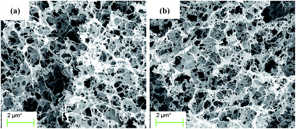 | ||
| Fig. 1 SEM of N-free CA-800 (a) and N-doped CA-800 (b). | ||
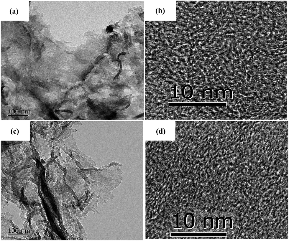 | ||
| Fig. 2 TEM images of N-free CA-800 (a and b) and N-doped CA-800 (c and d). | ||
 | ||
| Scheme 1 Illustration of the preparations and applications of hierarchical porous N-doped carbon aerogel. | ||
To further investigate the microstructure of the carbon aerogels with and without doped N, TEM images were recorded and shown in Fig. 2. N-Free CA-800 and N-doped CA-800 show a sheet-like microstructure (Fig. 2a and c), which is consist with the SEM. High-resolution images (Fig. 2b and d) reveal that both N-free CA-800 and N-doped CA-800 have a continuous porous structure with interconnected nanopores (less than 3 nm). Fig. 2b and d also indicate some lattice fringes (aligned graphitic layers), which correspond to the graphite (002) plane, implying partial graphitic structure. TEM, combining with SEM, demonstrates that both N-free CA-800 and N-doped CA-800 have well-developed hierarchical porous structure. Such an interconnected and continuous porous network will permit electrolytes to transfer fast throughout the material and decrease their diffusion distance. This feature is very beneficial for enhancing the dynamic performance and electrochemical properties as well as adsorption performances.
Fig. 3a shows the XRD patterns of N-free CA and N-doped CA prepared at different temperatures. All carbon aerogels show a similar diffraction feature with a main characteristic peak located at 2θ ≈ 23°. This broad and low intensity diffraction peak is attributed to the graphite (002) plane, suggesting that N-free CA and N-doped CA possess a low degree of graphitization.37 Raman spectra (Fig. 3b) show that all samples exhibit two distinct peaks located at 1320 cm−1 and 1591 cm−1. The strong peak at 1320 cm−1, signed as the D band, is associated with a double-resonance effect of disordered carbonaceous structure.38 The peak at 1591 cm−1, designated as the G band, corresponds to the ordered graphite in-plane vibrations with E2g symmetry. The low-intensity G band peak of N-doped CA-700 indicates an unperfect graphite structure and some defects existed in carbon framework.39 Overall, the intensities of D bands are obviously higher than those of G bands for all samples, indicating a higher amorphous carbon concentration in these carbon aerogels, which well agrees with the results from XRD and TEM. The partially aligned graphitic layers imply a good conductivity.
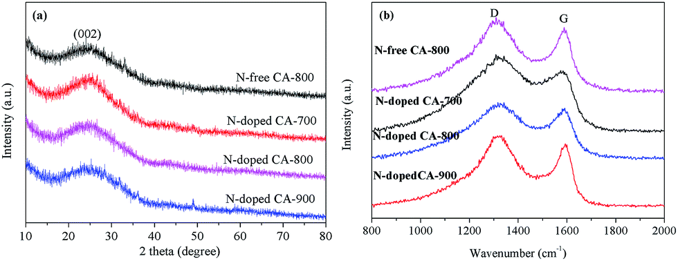 | ||
| Fig. 3 XRD pattern (a) and Raman spectra (b) of N-free CA and N-doped CA. | ||
Elemental analysis shows that N cannot be detected in N-free CA-800, while an N content of 4.62% can be detected in N-doped CA-800 (Table 1). Fig. 4a show that C and O present in N-free CA-800, while C, N, and O coexist in N-doped CA-800. The high-resolution C1s spectrum of N-free CA-800 (Fig. 4b) can be fitted to four peaks corresponding to sp2 (284.5 eV), sp3 (285.0), C–O (286.0 eV), and C![[double bond, length as m-dash]](https://www.rsc.org/images/entities/char_e001.gif) O (286.8 eV).40 In the high-resolution C1s spectrum of N-doped CA-800 (Fig. 4c), however, apart from the four C types mentioned above, C–N (285.5 eV) can be observed.10 Similarly, the N1s peak can be deconvolved into four components (Fig. 4e), corresponding to pyridinic N (N-1 at 398.0 eV), pyrrolic or pyridonic N (N-2 at 399.7 eV), quaternary N (N-3 at 400.8 eV), and oxidized N (N-4 at 402.5 eV).41,42 These results confirm that N is successfully doped in the carbon framework. It is reported that N located at the edges of graphene layers, e.g. N-1 and N-2, contributes to the pseudo-capacitance effect.43 Therefore, the N-doped carbon aerogel with hierarchical porous structure is expected to have good electrochemical performances.
O (286.8 eV).40 In the high-resolution C1s spectrum of N-doped CA-800 (Fig. 4c), however, apart from the four C types mentioned above, C–N (285.5 eV) can be observed.10 Similarly, the N1s peak can be deconvolved into four components (Fig. 4e), corresponding to pyridinic N (N-1 at 398.0 eV), pyrrolic or pyridonic N (N-2 at 399.7 eV), quaternary N (N-3 at 400.8 eV), and oxidized N (N-4 at 402.5 eV).41,42 These results confirm that N is successfully doped in the carbon framework. It is reported that N located at the edges of graphene layers, e.g. N-1 and N-2, contributes to the pseudo-capacitance effect.43 Therefore, the N-doped carbon aerogel with hierarchical porous structure is expected to have good electrochemical performances.
| Sample | N-Free CA-800 | N-Doped CA-800 |
|---|---|---|
| N wt% | — | 4.62 |
| SBET/m2 g−1 | 496 | 615 |
| Vtotal/cm3 g−1 | 0.46 | 0.64 |
| Vmicro/cm3 g−1 | 0.17 | 0.21 |
| CO2/mmol g−1 | 3.56 | 4.99 |
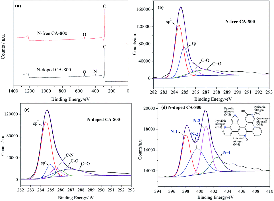 | ||
| Fig. 4 Surveys of N-free CA-800 and N-doped CA-800 (a), high-resolution C1s spectra of N-free CA-800 (b) and N-doped CA-800 (c), high-resolution N1s spectrum of N-doped CA-800 (d). | ||
Fig. 5a shows the N2 adsorption–desorption isotherms of N-free CA-800 and N-doped CA-800, while Fig. 5b shows their pore size distributions (obtained by density functional theory (DFT)). The two samples display a typical type-IV isotherm pattern with a small hysteresis loop at a higher relative pressure, indicating that mesopores and macropores exist in the carbon aerogels. A sharp increase at low relative pressure implies the existence of micropores.44 Fig. 5b demonstrates that N-doped CA-800 has more pores between 2 and 3 nm. On the other hand, mesopores larger than 3 nm are well developed for N-doped CA-800. From the porosity parameters summarized in Table 1, it is found that both the total pore volume (Vtotal) and the micropore volume (Vmicro) of N-doped CA-800 higher than those of N-free CA-800. For these reasons, N-doped CA-800 has a higher surface area (615 m2 g−1) than N-free CA-800 (496 m2 g−1). Therefore, N doping by annealing cellulose aerogel at NH3 atmosphere can develop more micropores and mesopores and thus increase the specific surface area.
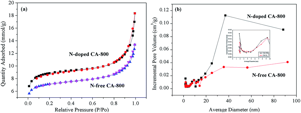 | ||
| Fig. 5 N2 adsorption–desorption isotherms (a) and pore size distributions calculated from the adsorption isotherms (b) of N-free CA-800 and N-doped CA-800. | ||
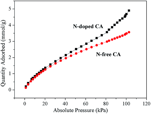
CO2 capture by carbon-based materials has spurred great interest due to their a variety of advantages, such as low cost, large pore volume, easy-to-design pore structure, hydrophobicity, high thermal stability, and low energy consumption for regeneration, etc.30,45 Among various carbons, N-doped carbons are especially promising because the doped N groups act as CO2-philic sites that increase the CO2 uptake capacity.46,47 The as-prepared hierarchical porous carbon aerogel with large amounts of N functionalities would be an excellent alternative for CO2 capture. Table 1 and Fig. 6 demonstrate that N-free CA-800 has a good CO2 adsorption capacity of 3.56 mmol g−1, while N-doped CA-800 shows an excellent CO2 capture performance with a very high CO2 adsorption capacity of 4.99 mmol g−1, which is much higher than that of N-free CA-800 and those of other N-doped carbon materials, such as N-doped porous carbon (2.41–3.20 mmol g−1),48,49 porous carbon nitride spheres (2.90 mmol g−1),50 and biomass-based porous carbon (4.8 mmol g−1).45 The excellent CO2 adsorption performance of N-doped CA-800 can be mainly due to a large fraction of nanopores and large amounts of nitrogen groups.51 Therefore, N-doped CA-800 is a high-performance porous carbon for CO2 capture.
 | ||
| Fig. 6 CO2 adsorption isotherms of N-free CA-800 and N-doped CA-800. | ||
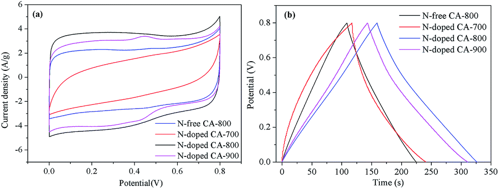
Cyclic voltammetry (CV) and galvanostatic charge/discharge were investigated to examine the electrochemical properties of N-doped CA-800 in 1.0 M H2SO4 in a three-electrode system. For comparison, pristine N-free CA was also tested, as shown in Fig. 7. The CV curve of N-doped CA-700 is irregular (Fig. 7a), indicating a poor conductivity due to low annealing temperature. The CV curve of N-free CA-800 shows a typical rectangular shape, indicating a perfect electrical double layer (reversible adsorption and desorption of the ions). N-Doped CA-800 and N-doped CA-900 show a less rectangular shape, which may indicate that the capacitive response results from the combination of electrical double-layer formation and redox reactions due to the N functionalities.52,53 As compared with the linear and symmetrical charge/discharge curve of N-free CA-800 (Fig. 7b), the charge/discharge curves of N-doped CA-700, N-doped CA-800, and N-doped CA-900 are not strictly symmetrical and slightly distorted, implying the pseudo-capacitive behaviour of the active functional N groups.15,41 These results are consistent with those from CV testing. The specific capacitances of N-doped CA-700, N-doped CA-800, and N-doped CA-900 are 155 F g−1, 209 F g−1, and 210 F g−1 at a current density of 1.0 A g−1, respectively, which are much higher than that of N-free CA (145 F g−1). The higher capacitance of N-doped CA-800 can be attributed to the doped N that can result in the pseudo-capacitive effect and enhance the surface hydrophilicity to facilitate charge-transfer and electrolyte–electrode interactions.
 | ||
| Fig. 7 CV curves at 20 mV s−1 (a) and galvanostatic charge/discharge curves at 1.0 A g−1 (b) of carbon aerogels. | ||
To further understand the electrochemical performances of the as-prepared carbon aerogels, the CV curves at different scan rates and galvanostatic charge/discharge curves at different current densities were examined, as shown in Fig. 8. The CV curves of N-free CA-800 and N-doped CA-800 exhibit an approximately rectangular shape at a low scan rate and maintain a quasi-rectangular shape even at a high scan rate of 200 mV s−1 (Fig. 8a and b). Fig. 8c demonstrates that the capacitances of N-doped CA-800 at different scan rates from CV testing are much higher than those of N-free CA-800. And the specific capacitance of N-doped CA-800 shows only a slight decrease from 389 F g−1 at 5 mV s−1 to 329 F g−1 at 200 mV s−1, indicating near-ideal capacitive behavior.
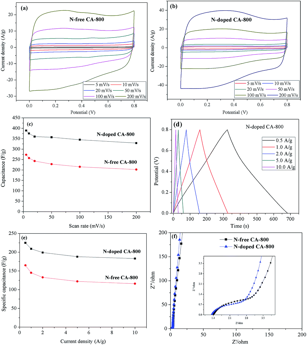 | ||
| Fig. 8 Electrochemical behaviours of N-free CA and N-doped CA: CV curves at different scan rates (a and b), specific capacitances as a function of scan rate (c), galvanostatic charge/discharge curves at different current densities (d), specific capacitances as a function of current density (e), and Nyquist plots (f). | ||
The galvanostatic charge/discharge curves of the carbon materials at different current densities are shown in Fig. 8d and e. The specific capacitance of N-doped CA-800 is high up to 225 F g−1 at 0.5 A g−1 and remains 183 F g−1 even at a high current density of 10 A g−1; while the specific capacitances of N-free CA-800 at 0.5 A g−1 and 10 A g−1 are 165 F g−1 and 116 F g−1, respectively. These results demonstrate that N-doped CA-800 has a more outstanding specific capacitance. In general, the specific capacitance gradually decreases with the increase in discharging current density owing to that larger current may block the entrances of the pores. In our work, when the discharge current density increased from 0.5 to 10 A g−1, the capacitance retention of N-doped CA-800 is high up to 81%, which demonstrates that N-doped CA-800 has an excellent rate capability and is very suitable for high current density application. In addition, the voltage drop at the initiation of discharge is very small even at a high current density of 10 A g−1, indicating a very low equivalent series resistance (ESR).
N-Doped CA-800 has a high specific capacitance (225–185 F g−1 at current densities of 0.5–10 A g−1) that is not only superior to those of cellulose-based N-free carbon aerogel (142.1 F g−1 at 0.5 A g−1)24 and meso-porous and micro-porous carbon materials obtained by directly carbonizing cellulose fibers (150 F g−1 at 0.5 A g−1),17 but also superior to those of other meso-porous and micro-porous carbons derived from biomass resources such as silk proteins (216 F g−1 at 0.5 A g−1),54 hair (180 F g−1 at 0.5 A g−1),55 and chitosan (222 F g−1 at 0.5 A g−1).56 Moreover, this novel N-doped carbon aerogel has a higher specific capacitance than the N-doped graphene (220 F g−1 at 0.5 A g−1),57 N-doped CNT (180 F g−1 at 0.5 A g−1)58 and N-doped carbon fiber (202 F g−1 at 0.5 A g−1).53 The high specific capacitance and excellent rate capability can be ascribed to the hierarchical porous structure, as well as N atoms located in the carbon network. This unique structure provides large amounts of adsorption sites and allows the efficient and fast transport of ions in the 3D frame work.
Fig. 8f shows the Nyquist plots of N-free CA-800 and N-doped CA-800 at an open circuit potential. In the low-frequency region, both N-free CA-800 and N-doped CA-800 have a steep capacitive spike with an almost 90° angle, indicating a nearly ideal capacitor behavior due to that electrolyte ions can fully infiltrate the internal pores. However, the plot slope of N-doped CA-800 is higher than that of N-free CA-800, showing a better pore accessibility for electrolytes in N-doped CA-800. This can be attributed to more micro- and mesopores in N-doped CA-800, as shown Fig. 5b and Table 1. The real axis intercept corresponds to the equivalent series resistance (ESR), whereas the large radius of the semicircle impedance of electrode materials commonly represents charge-transfer resistance between electrode material and the electrolyte. Obviously, N-doped CA-800 displays a semicircle impedance that is smaller than that of N-free CA-800 at a high frequency region, revealing that N-doped CA-800 has a lower charge-transfer resistance on the electrode surface. In addition, N-doped CA-800 has a lower ESR value (1.33 Ω) than N-free CA-800 (1.40 Ω), which indicate a better conducting behavior of N-doped CA-800 due to a faster diffusion of electrolytes. Therefore, the presence of N species in the hierarchical porous carbon structure can guarantee the faster diffusion of electrolytes in the porous network. Additionally, N-doped CA-800 displays a negligible capacitance degradation after 5000 cycles (Fig. 9). The specific capacitance still maintains 94% of its initial specific capacitance in 1.0 M H2SO4, indicating that N-doped CA-800 is a very stable electrode material.
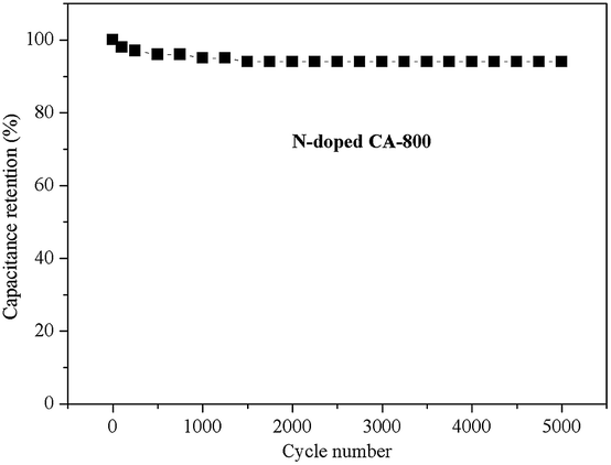 | ||
| Fig. 9 The cycling stability of N-doped CA-800 at a current density of 1.0 A g−1. | ||
Thus, the high CO2 uptake and electrochemical performances of N-doped CA-800 can be ascribed to its unique features: (1) the hierarchical porous structure containing numerous macropores, mesopores, and micropores permits electrolytes to transfer fast; (2) good conductivity resulting from partial graphitization structure allows electrons transport in a high-rate way and electrochemical stability; (3) remarkably, the presence of N species in carbon network improves its electrical conductivity, wettability, and thus results in a high specific capacitance. It can be also foreseen that this N-doped CA has great potential applications in various electrochemical catalysis due to the unique physical and chemical properties.
Conclusions
Dissolving–gelling process allowed producing hierarchical porous aerogel. Annealing cellulose aerogel in an ammonia atmosphere produced a hierarchical porous N-doped carbon aerogel with more mesopores and micropores. The N-doped carbon aerogel had not only a high capacitance of 225 F g−1 and an excellent cycle life (6% loss after 5000 cycles), but also a exceptional CO2 adsorption capacity of 4.99 mmol g−1 that is much higher than those of other carbon materials due to the unique porous structure and physicochemical properties as a result of doped N. These features, together with the superior advantages of raw material (cellulose) such as renewability, abundance, low cost, environment benefit, make this novel N-doped carbon aerogel a high-performance and promising porous carbon for energy storage, adsorption, catalysis, gas storage and so on.Acknowledgements
This work was supported by National Natural Science Foundation of China (21506068), Pearl River S&T Nova Program of Guangzhou, Guangdong natural Science Foundation (2014A030310319), Major State Basic Research Projects of China (973-2012CB215302), Fundamental Research Funds for the Central Universities.Notes and references
- L. L. Zhang and X. Zhao, Chem. Soc. Rev., 2009, 38, 2520–2531 RSC.
- L. Qie, W. Chen, H. Xu, X. Xiong, Y. Jiang, F. Zou, X. Hu, Y. Xin, Z. Zhang and Y. Huang, Energy Environ. Sci., 2013, 6, 2497–2504 Search PubMed.
- C. Zheng, X. Zhou, H. Cao, G. Wang and Z. Liu, J. Power Sources, 2014, 258, 290–296 CrossRef CAS.
- G. Wang, H. Wang, X. Lu, Y. Ling, M. Yu, T. Zhai, Y. Tong and Y. Li, Adv. Mater., 2014, 26, 2676–2682 CrossRef CAS PubMed.
- X. Wang, L. Liu, X. Wang, L. Bai, H. Wu, X. Zhang, L. Yi and Q. Chen, J. Solid State Electrochem., 2011, 15, 643–648 CrossRef CAS.
- R. Saliger, U. Fischer, C. Herta and J. Fricke, J. Non-Cryst. Solids, 1998, 225, 81–85 CrossRef CAS.
- J. Zhao, J. Chen, S. Xu, M. Shao, Q. Zhang, F. Wei, J. Ma, M. Wei, D. G. Evans and X. Duan, Adv. Funct. Mater., 2014, 24, 2938–2946 CrossRef CAS.
- Y. Sun, Q. Wu and G. Shi, Energy Environ. Sci., 2011, 4, 1113–1132 CAS.
- C. Liu, Z. Yu, D. Neff, A. Zhamu and B. Z. Jang, Nano Lett., 2010, 10, 4863–4868 CrossRef CAS PubMed.
- P. Hao, Z. Zhao, Y. Leng, J. Tian, Y. Sang, R. I. Boughton, C. Wong, H. Liu and B. Yang, Nano Energy, 2015, 15, 9–23 CrossRef CAS.
- L. Sun, Y. Fu, C. Tian, Y. Yang, L. Wang, J. Yin, J. Ma, R. Wang and H. Fu, ChemSusChem, 2014, 7, 1637–1646 CrossRef CAS PubMed.
- J. W. Jeon, L. Zhang, J. L. Lutkenhaus, D. D. Laskar, J. P. Lemmon, D. Choi, M. I. Nandasiri, A. Hashmi, J. Xu and R. K. Motkuri, ChemSusChem, 2015, 8, 428–432 CrossRef CAS PubMed.
- S. Leguizamon, K. P. Díaz-Orellana, J. Velez, M. C. Thies and M. E. Roberts, J. Mater. Chem. A, 2015, 3, 11330–11339 CAS.
- X. Y. Chen, C. Chen, Z. J. Zhang and D. H. Xie, J. Mater. Chem. A, 2013, 1, 10903–10911 CAS.
- B. Xu, S. Hou, G. Cao, F. Wu and Y. Yang, J. Mater. Chem., 2012, 22, 19088–19093 RSC.
- B. Grzyb, C. Hildenbrand, S. Berthon-Fabry, D. Bégin, N. Job, A. Rigacci and P. Achard, Carbon, 2010, 48, 2297–2307 CrossRef CAS.
- H. Wang, Z. Xu, A. Kohandehghan, Z. Li, K. Cui, X. Tan, T. J. Stephenson, C. K. King'ondu, C. M. Holt and B. C. Olsen, ACS Nano, 2013, 7, 5131–5141 CrossRef CAS PubMed.
- Z. Li, Z. Xu, X. Tan, H. Wang, C. M. Holt, T. Stephenson, B. C. Olsen and D. Mitlin, Energy Environ. Sci., 2013, 6, 871–878 CAS.
- J. Ding, H. Wang, Z. Li, A. Kohandehghan, K. Cui, Z. Xu, B. Zahiri, X. Tan, E. M. Lotfabad and B. C. Olsen, ACS Nano, 2013, 7, 11004–11015 CrossRef CAS PubMed.
- K. Xie, X. Qin, X. Wang, Y. Wang, H. Tao, Q. Wu, L. Yang and Z. Hu, Adv. Mater., 2012, 24, 347–352 CrossRef CAS PubMed.
- S. Bose, T. Kuila, A. K. Mishra, R. Rajasekar, N. H. Kim and J. H. Lee, J. Mater. Chem., 2012, 22, 767–784 RSC.
- W. Luo, B. Wang, C. G. Heron, M. J. Allen, J. Morre, C. S. Maier, W. F. Stickle and X. Ji, Nano Lett., 2014, 14, 2225–2229 CrossRef CAS PubMed.
- M. Zhi, C. Xiang, J. Li, M. Li and N. Wu, Nanoscale, 2013, 5, 72–88 RSC.
- P. Hao, Z. Zhao, J. Tian, H. Li, Y. Sang, G. Yu, H. Cai, H. Liu, C. Wong and A. Umar, Nanoscale, 2014, 6, 12120–12129 RSC.
- D. Yu, E. Nagelli, F. Du and L. Dai, J. Phys. Chem. Lett., 2010, 1, 2165–2173 CrossRef CAS.
- S. Yang, X. Feng, X. Wang and K. Müllen, Angew. Chem., Int. Ed., 2011, 50, 5339–5343 CrossRef CAS PubMed.
- X. Wang, X. Li, L. Zhang, Y. Yoon, P. K. Weber, H. Wang, J. Guo and H. Dai, Science, 2009, 324, 768–771 CrossRef CAS PubMed.
- K. Gong, F. Du, Z. Xia, M. Durstock and L. Dai, Science, 2009, 323, 760–764 CrossRef CAS PubMed.
- S. Maldonado and K. J. Stevenson, J. Phys. Chem. B, 2005, 109, 4707–4716 CrossRef CAS PubMed.
- N. P. Wickramaratne, J. Xu, M. Wang, L. Zhu, L. Dai and M. Jaroniec, Chem. Mater., 2014, 26, 2820–2828 CrossRef CAS.
- Y. Li, J. Wang, X. Li, J. Liu, D. Geng, J. Yang, R. Li and X. Sun, Electrochem. Commun., 2011, 13, 668–672 CrossRef CAS.
- Y. Lu, F. Zhang, T. Zhang, K. Leng, L. Zhang, X. Yang, Y. Ma, Y. Huang, M. Zhang and Y. Chen, Carbon, 2013, 63, 508–516 CrossRef CAS.
- L. L. Zhang, X. Zhao, H. Ji, M. D. Stoller, L. Lai, S. Murali, S. Mcdonnell, B. Cleveger, R. M. Wallace and R. S. Ruoff, Energy Environ. Sci., 2012, 5, 9618–9625 CAS.
- Y. Zhao, C. Hu, Y. Hu, H. Cheng, G. Shi and L. Qu, Angew. Chem., 2012, 124, 11533–11537 CrossRef.
- C. Wang, Y. Li, X. He, Y. Ding, Q. Peng, W. Zhao, E. Shi, S. Wu and A. Cao, Nanoscale, 2015, 7, 7550–7558 RSC.
- J. Cai, S. Kimura, M. Wada, S. Kuga and L. N. Zhang, ChemSusChem, 2008, 1, 149–154 CrossRef CAS PubMed.
- L. Qie, W. M. Chen, Z. H. Wang, Q. G. Shao, X. Li, L. X. Yuan, X. L. Hu, W. X. Zhang and Y. H. Huang, Adv. Mater., 2012, 24, 2047–2050 CrossRef PubMed.
- Z. Sun, D. Popa, T. Hasan, F. Torrisi, F. Wang, E. J. Kelleher, J. C. Travers, V. Nicolosi and A. C. Ferrari, Nano Res., 2010, 3, 653–660 CrossRef CAS.
- N. Shimodaira and A. Masui, J. Appl. Phys., 2002, 92, 902–909 CrossRef CAS.
- D. C. Guo, J. Mi, G. P. Hao, W. Dong, G. Xiong, W. C. Li and A. H. Lu, Energy Environ. Sci., 2013, 6, 652–659 CAS.
- F. Kapteijn, J. Moulijn, S. Matzner and H. P. Boehm, Carbon, 1999, 37, 1143–1150 CrossRef CAS.
- C. X. Guo and C. M. Li, Energy Environ. Sci., 2011, 4, 4504–4507 CAS.
- C. O. Ania, V. Khomenko, E. Raymundo-Piñero, J. B. Parra and F. Beguin, Adv. Funct. Mater., 2007, 17, 1828–1836 CrossRef CAS.
- B. Chang, Y. Guo, Y. Li, H. Yin, S. Zhang, B. Yang and X. Dong, J. Mater. Chem. A, 2015, 3, 9565–9577 CAS.
- M. Sevilla and A. B. Fuertes, Energy Environ. Sci., 2011, 4, 1765–1771 CAS.
- Y. Zhao, X. Liu, K. X. Yao, L. Zhao and Y. Han, Chem. Mater., 2012, 24, 4725–4734 CrossRef CAS.
- Y. Zhao, K. X. Yao, B. Teng, T. Zhang and Y. Han, Energy Environ. Sci., 2013, 6, 3684–3692 CAS.
- G. P. Hao, W. C. Li, D. Qian and A. H. Lu, Adv. Mater., 2010, 22, 853–857 CrossRef CAS PubMed.
- J. M. Gu, W. S. Kim, Y. K. Hwang and S. Huh, Carbon, 2013, 56, 208–217 CrossRef CAS.
- Q. Li, J. Yang, D. Feng, Z. Wu, Q. Wu, S. S. Park, C. S. Ha and D. Zhao, Nano Res., 2010, 3, 632–642 CrossRef CAS.
- R. Babarao, S. Dai and D. Jiang, J. Phys. Chem. C, 2012, 116, 7106–7110 CAS.
- Y. Xu, Z. Lin, X. Huang, Y. Wang, Y. Huang and X. Duan, Adv. Mater., 2013, 25, 5779–5784 CrossRef CAS PubMed.
- L. F. Chen, X. D. Zhang, H. W. Liang, M. Kong, Q. F. Guan, P. Chen, Z. Y. Wu and S. H. Yu, ACS Nano, 2012, 6, 7092–7102 CrossRef CAS PubMed.
- Y. S. Yun, S. Y. Cho, J. Shim, B. H. Kim, S. J. Chang, S. J. Baek, Y. S. Huh, Y. Tak, Y. W. Park and S. Park, Adv. Mater., 2013, 25, 1993–1998 CrossRef CAS PubMed.
- Z. Guo, Q. Zhou, Z. Wu, Z. Zhang, W. Zhang, Y. Zhang, L. Li, Z. Cao, H. Wang and Y. Gao, Electrochim. Acta, 2013, 113, 620–627 CrossRef CAS.
- Q. Liang, H. Su, J. Yan, C. Leung, S. Cao and D. Yuan, Chin. J. Catal., 2014, 35, 1078–1083 CrossRef CAS.
- Z. Y. Sui, Y. N. Meng, P. W. Xiao, Z. Q. Zhao, Z. X. Wei and B. H. Han, ACS Appl. Mater. Interfaces, 2015, 7, 1431–1438 CAS.
- B. You, L. Wang, L. Yao and J. Yang, Chem. Commun., 2013, 49, 5016–5018 RSC.
| This journal is © The Royal Society of Chemistry 2016 |