CoP/CoN heterostructural active centers supported on nitrogen carbon nanorod arrays as freestanding high-performance trifunctional electrocatalysts†
Linming
Bai
a,
Dan
Wang
a,
Hongchen
Shen
b,
Wenlong
Wang
a,
Shanshan
Li
 *a and
Wei
Yan
 *a
*a
aXi'an Key Laboratory of Solid Waste Recycling and Resource Recovery, Department of Environmental Engineering, Xi'an Jiaotong University, Xi'an, 710049, China. E-mail: yanwei@xjtu.edu.cn; shanshan0320@xjtu.edu.cn
bDepartment of Civil and Environmental Engineering, Rice University, Houston, TX 77005, USA
First published on 8th January 2024
Abstract
Developing high-activity and long-term durable trifunctional electrocatalysts for the oxygen reduction reaction (ORR), oxygen evolution reaction (OER) and hydrogen evolution reaction (HER) is of crucial significance and demanding. In this work, a CoP/CoN heterostructural active center supported by nitrogen carbon nanorod arrays on carbon cloth catalyst (CoP/CoN@NCNRs/CC) is reported and acts as a self-supported electrode for zinc–air batteries and water splitting. Both density functional theory calculation (DFT) and experimental results reveal that the favourable catalytic performance is due to the highly dispersed active sites where Co–Nx–C with ORR and OER activity and CoP with OER and HER activity exhibited a synergistic role. Furthermore, the NCNRs can protect the active sites from corrosion and participate in the ORR. CoP/CoN@NCNRs/CC as an air electrode for liquid zinc–air batteries possesses a great power density and energy density and shows superior stability with a long operating life of more than 420 h at 10 mA cm−2. The all-solid-state Zn–air batteries and water splitting device are self-assembled and both of them have potential for application in flexible electronics and new energy devices.
1. Introduction
As fossil fuel depletion contributes to environmental and climate-related problems, more attention is paid to renewable and clean energy. Exploring sustainable energy-related conversion and storing devices is viewed as an effective means of addressing the conventional energy crisis.1–3 In terms of energy storage devices, core principles of promising energy conversion technologies for the next generation such as water splitting, fuel cells and Zn–air batteries focus on electrocatalytic processes: oxygen reduction reaction (ORR), oxygen evolution reaction (OER) and hydrogen evolution reaction (HER).4–7 To date, IrO2/RuO2 and Pt-based nanomaterials are already regarded as benchmark electrocatalysts for electrocatalytic reactions, while the high price and poor earth abundance of these noble-metal catalysts limit commercial application prospects.8–10 Furthermore, it is difficult for single noble metal catalysts to meet the demands of tri-functional catalytic reactions for energy conversion devices synchronously. In this regard, developing multifunctional catalysts with highly catalytic performance while being cost-efficient and long-lived is still challenging and alluring.11,12Due to the ideal theoretical energy density of 1086 W h kg−1, bargain price and excellent safety of aqueous electrolytes, zinc–air batteries (ZABs) have enormous potential for a wide variety of application areas, e.g., automotive and flexible electronics.13 Primary ZABs were commercially launched on the market in 1932, as a substitute for 1.35 V mercury batteries, the production of which is stopped now.14 Although commercially developed earlier, ZABs are far from reaching their full potential as storage batteries because of the sluggish oxygen kinetics involved reactions and greater overpotential for the ORR and OER on the cathode.15 Significant achievements have been made for efficient oxygen electrocatalysts. Of particular interest, metal–nitrogen–carbon (M–N–C) catalysts were regarded as highly efficient catalysts with excellent stabilities and ORR activity compared with Pt-based catalysts.16–18 For instance, Xu et al. demonstrated that (Zn, Cu)–N–C exerted excellent activity for the ORR: the ORR performance was improved with the optimization of the O2 adsorption mode and the synergy effect of adjacent Zn and Cu metal sites. The calculation results indicate that the linear O2 molecule was efficiently activated by the nitrogen-doped carbon support (Zn, Cu)–N–C via non-covalent interaction causing the metal 3d orbitals to overlap more with the O 2p orbital effectively.19 Liu et al. also proved that a MOF-derived Fe–N–C material reveals stability and excellent ORR activity, and the half-wave potentials (E1/2) are 0.926 V (vs. RHE) and 0.8 V (vs. RHE) in alkaline media and acidic media, respectively.20 As for the OER and HER, multiple studies have investigated and demonstrated that transition metal phosphides possessed higher catalytic activity for both reactions.21 The P atom attracts electrons from metal atoms easily due to its strong electronegativity and acts as a Lewis base to react with protons during an electrocatalytic reaction.22,23 Meanwhile, transition metal phosphides face the problems of limited electrical conductivity and poor dispersion which can be tackled by introducing carbon.24 Therefore, it is speculated that high-performance multifunctional catalysts can be fabricated by compositing metal phosphides and nitrogen–carbon materials.
On the other hand, as smart energy storage has been revolutionized to an all-time high, flexible batteries have drawn extensive attention on account of their ability to make electronics more bendable, adaptable and comfortable. ZABs have widespread potential in flexible devices due to the relatively mild chemical activity of zinc that can be used as an anode exposed to air, and apyrous aqueous electrolytes are safer than organic electrolytes of lithium batteries during the reaction. Therefore, the flexibility and mechanical robustness of air electrodes are two key factors needed to be considered when assembling flexible ZABs.25–27 Powder is the main form of electrocatalyst studied so far. The catalyst powder mixed with a polymer binder and additive in the fabrication would reduce the conductivity and flexibility of the electrode in ZABs, hindering the charge transfer between the catalyst layer and conduction substrate. Furthermore, unavoidable mechanical forces and material stresses will trigger aggregation, corrosion and deterioration of the powder catalysts during sample preparation and testing.28,29 Therefore, developing multifunctional non-noble metal catalysts with flexibility and excellent catalytic properties is still challenging.
In this study, we successfully synthesized a three-dimensional integrated binderless self-standing flexible electrode by making CoP/CoN heterostructural active centers confined on the top of N-doped carbon nanorods (NCNRs) as favorable electrodes for high-efficiency trifunctional catalysis. The as-prepared CoP/CoN@NCNRs/CC has abundant active sites, where the CoP/CoN heterostructural nanoparticles and hierarchical NCNRs improve the intrinsic catalytic activity,30 and DFT calculation and experimental results reveal that CoP played a significant role in the OER and HER, and CoN and NCNRs are effective in ORR and OER processes. The structure of CoP/CoN particles on the head of a carbon nanorod makes the catalytic sites more dispersed, and the carbon layer of CNRs protects the CoP/CoN particles from aggregation and electrolyte corrosion. In addition, in situ growth of CoP/CoN@NCNRs on carbon cloth ensures good conductivity and flexibility for the material. The catalyst facilitates the chemisorption capacity of O species and lower OH species adsorption energy, and it is beneficial for the binding of active substances at the beginning stage and the desorption of products at the end of the reaction following a four-electron catalysis mechanism. Based on the above advantages, the as-prepared electrocatalyst shows good catalytic activity for the ORR, OER and HER compared with Pt/C and RuO2.31–33 Due to the intrinsic flexibility and stability of the material, it can be used as an air electrode for ZABs and water splitting. The homemade ZAB achieves a long operating time of 420 h and the ZAB possesses excellent flexibility performance under different bending degrees, and the successful development of this material enables the large-scale development of low-cost and multifunctional catalysts for ZABs.
2. Experimental section
2.1. Materials
Carbon cloth (CC, W0S1009) was purchased from CeTech Co., Ltd. Before using, the CC was cut into small pieces of sizes 3 cm × 4 cm and then soaked in 98% nitric acid for 8 h, followed by washing with a copious amount of deionized water to eliminate the acid. Finally, the treated CC was dried at 60 °C overnight.Co(NO3)2·6H2O, Co(NH2)2, NH4F, and Zn(OAc)2 were provided by Adamas-Beta. RuO2 and 20% Pt/C were supplied by Johnson Matthey. 5% Nafion solution, a zinc plate and polyvinyl alcohol (PVA, MW = 195![[thin space (1/6-em)]](https://www.rsc.org/images/entities/char_2009.gif) 000) were provided by Alfa Aesar.
000) were provided by Alfa Aesar.
2.2. Preparation of CoP/CoN@NCNRs/CC by three-step treatment
![[thin space (1/6-em)]](https://www.rsc.org/images/entities/char_2009.gif) :
:![[thin space (1/6-em)]](https://www.rsc.org/images/entities/char_2009.gif) 1 wt%) were then added to form ink. The catalyst ink was sonicated for 1 h and then coated on treated CC (0.1 mg cm−2), the same as CoP/CoN@NCNRs/CC.
1 wt%) were then added to form ink. The catalyst ink was sonicated for 1 h and then coated on treated CC (0.1 mg cm−2), the same as CoP/CoN@NCNRs/CC.
The material characterization, electrocatalysis and battery measurements are presented in the ESI.†
3. Results and discussion
3.1. Characterizations of the synthetic material
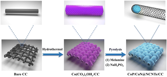
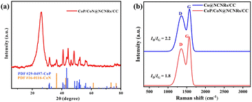
Scheme 1 shows the synthesis of CoP/CoN@NCNRs on the flexible carbon cloth. Co(CO3)xOHy/CC nanoneedle arrays were generated on a CC substrate by a hydrothermal method. The prepared material then was calcined with melamine under a nitrogen atmosphere at 800 °C, where the Co2+ compounds were reduced to cobalt by the reducing gas from the thermal decomposition of melamine. The elemental cobalt acted as the active site to catalyze N-doped CNR growth in situ along the needle arrays on CC. The final morphology formed is cobalt particles arranged in the head of the carbon rods. Co@NCNRs/CC was thermally activated in NaH2PO2, forming CoP/CoN@NCNRs/CC as the final trifunctional electrocatalyst. Co@NCNRs/CC and CoP/CC were prepared as comparisons by similar methods.The XRD patterns of CoP/CoN@NCNRs/CC and contrast catalysts are exhibited in Fig. 1a and S1.† Two pronounced peaks of the XRD spectrum at 2θ = 26° and 45°, corresponding to the (002) and (101) planes of carbon, confirm a typical structure of graphitized carbon (JCPDS: 01-0640). CoP generates diffraction peaks at around 31.5°, 44.3°, 48.4°, 52.4° and 56°, which are assigned to the crystal planes (011), (210), (202), (103) and (301) of CoP (JCPDS: 29-0497), respectively. Sharp XRD peaks from the diffraction of the crystal (111), (200), (220), (311), and (222) were found, indicating the existence of CoN in the prepared material (JCPDS: 16-0116). The XRD patterns of CoP/CoN@NCNRs/CC could confirm CoP species (JCPDS: 29-0497) and CoN species (JCPDS: 16-0116). The results proved the existence of CoP and CoN species in CoP/CoN@NCNRs/CC. As shown in Fig. 1b, the Raman spectrum revealed a specific pair of D and G bands at 1346 cm−1 and 1579 cm−1, respectively, indicating the existence of both defective carbon and graphite carbon in the sample.36,37 The presence of disordered graphite was proved by the D band. The ID/IG peak intensity ratios are 2.2 and 1.8 for Co@NCNRs/CC and CoP/CoN@NCNRs/CC, proving that the secondary calcination increases the graphitization degree of carbon materials, which can improve the electrical conductivity of the whole material.38
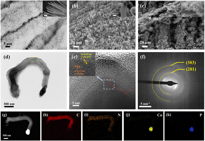
Delicate morphology studies were carried out. The SEM image (Fig. 2a) exhibits uniform Co(CO3)xOHy/CC nanoneedle arrays with a diameter of about 200 nm. After calcination with melamine, the nanoneedle arrays turned into carbon nanorods (about 230 nm) with the cobalt nanoparticles on top (Fig. 2b). As shown in Fig. 2c, the morphology of CoP/CoN@NCNRs/CC was similar to that of (Co(CO3)xOHy/CC), but the size was bigger than that of the precursor. The phenomena may be ascribed to the etching result of the phosphating process, which causes the hierarchical carbon structure of CNRs (Fig. 2d). The CoP/CoN particles are encapsulated in the carbon layer (Fig. S2†). Stacked carbon layers can be seen from the filament-like carbon nanostructures that are aligned parallel to the direction of the metal–carbon interface. This phenomenon has been demonstrated earlier to show that the (111) surface of face-centered cubic (fcc) metals can induce parallel precipitation of the graphite layers along the surface of metal particles.39,40 As shown in Fig. 2e, the carbon nanostructure with a d-spacing of 0.33 nm is indexed to the (002) planes of graphitic carbon layers. The lattice fringe spacings of the nanoparticles (NPs) are 0.27 nm and 0.24 nm, respectively, which matched the (002) and (111) planes of CoP and CoN. The results demonstrate the existence of CoP/CoN heterogeneous structures. The (111) plane of CoN is relative outer layer of the CoN/CoP paticle, and proves the growth mechanism of the filament-like architecture. Elemental mapping images of a single carbon rod show that the cobalt and phosphorus are mainly concentrated in the head particles, and the N element can be seen in most areas of the top, and it shows that there is a possibility of interaction between the N element and metal element (Fig. 2g–k). Elemental analysis shows a relatively even distribution of C and N elements of the carbon matrix, and Co and P elements are relatively dispersed, suggesting that the catalysts are separated and not easily reunited (Fig. S3†). The corresponding ring-type diffraction pattern of the CoP nanoparticles can be well indexed to the (201) and (303) planes of CoP (JCPDS: 29-0497), supporting their crystalline nature (Fig. 2f). The above results demonstrate the successful anchoring of CoP/CoN heterostructural NPs on the NCNRs.
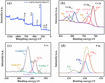
To further determine the elemental composition of the catalyst. As shown in Fig. 3a, XPS analysis was performed to demonstrate the existence of Co, C, N, P, and O in CoP/CoN@NCNRs/CC. Most of the O species are attributed to the acid-treated CC (Fig. S4†), and the C–O bond shown in Fig. S5† also certifies the surface of NCNRs own abundant oxygen-containing groups, implying defects over the NCNR matrix (Fig. S5†).31 The high-resolution spectrum of Co 2p in Fig. 3b can be well-fitted into six peaks: the peaks located at ∼782.3 and 797.4 eV are ascribed to the Co 2p3/2 and Co 2p1/2 of the Co2+ bonds, confirming the presence of Co–P and Co–N bonds, while others at ∼785.2 and 800.2 eV are for Co2+/Co3+ species; ∼788.3 and 804.2 eV are for satellite peaks, and these peaks should be related to the superficial oxidation of cobalt phosphides.30,41,42 The existence of Co–Nx means strong interaction between the N-doped CNR skeleton and cobalt NPs, which facilitates charge and mass transfer. The high-resolution N 1s spectra (Fig. 3c) of CoP/CoN@NCNRs/CC can be divided into five peaks at around 397.3 eV, ∼399.1 eV, ∼400 eV, ∼401.6 eV and ∼403.8 eV related to pyridinic-N, Co–Nx, Pyrrolic N, graphitic-N and oxidized-N, respectively, illustrating that the nitrogen evenly disperses on the carbon nanowalls. It also further corroborates the existence of the Co–Nx bonds. Generally, graphitic N might be conducive to the boosted stability of the material and electrical conductivity. Furthermore, the Co–Nx bonds could contribute to the electrocatalytic performance, acting as adsorption active sites.43 As reported previously, the electron-accepting pyridine-like N species would impart a relatively high positive charge density to the neighboring sp2-bonded C atoms, facilitating reactant adsorption (e.g., OH and O2 species), promoting the electron transfer between the catalyst surface and reaction intermediates, and efficiently catalyzing the ORR and OER with favorable reaction kinetics.44 The Co–O and N–O bonds were caused by inevitable surface oxidation. The presence of CoP was confirmed by P 2p3/2 (∼128.5 eV) and P 2p1/2 (∼129.8 eV) in the P 2p XPS spectrum (Fig. 3d).45
3.2. Oxygen electrocatalytic activities
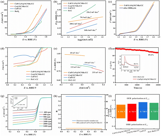
As vital indices of ZABs, the bifunctional OER and ORR activities of the prepared self-supported catalysts were tested without IR compensation. The OER performance was evaluated by LSV, CV and EIS measurements in 1 M KOH with saturated oxygen. According to Fig. 4a, the LSV curve of CoP/CoN@NCNRS/CC exhibits a high OER activity with a low overpotential (Ej=10) of 234 mV at 50 mA cm−2, superior to Co@NCNRS/CC (323 mV), CoP/CC (370 mV) and RuO2–CC (343 mV) at 50 mA cm−2. The two curves of Co@NCNRS/CC and CoP/CC rise rapidly at low potential, which may be caused by oxidation. The Tafel plots were measured for evaluating OER electrocatalytic kinetics (Fig. 4b). The Tafel slope of CoP/CoN@NCNRs/CC is 60.2 mV dec−1, which is lower than that of Co@NCNRS/CC (162.7 mV dec−1), CoP/CC (200.9 mV dec−1) and even RuO2–CC (79.5 mV dec−1). The stability of CoP/CoN@NCNRs/CC toward the OER was further verified through multiple cycle voltammetry tests under 50 mV s−1. Fig. 4c shows that after a 2000-cycle CV test, the LSV curve of CoP/CoN@NCNRS/CC changed slightly (about 30 mV) compared to the initial curve at the end of the endurance test, showing a good application prospect for the OER. EIS was conducted to understand the reason for the performance difference among these materials (Fig. S6†). The results show that CoP/CoN@NCNRS/CC has more negligible charge transfer resistance (Rct) and faster electron transport than the other materials.The electrocatalytic properties of the synthesized materials toward the ORR were measured in an O2-saturated 0.1 M KOH solution. The half-wave potential (E1/2) of CoP/CoN@NCNRs/CC is 0.86 V vs. RHE, which is more positive than that of Pt/C (0.80 V vs. RHE). The diffusion-limiting current density for CoP/CoN@NCNRs/CC is ∼4.0 mA cm−2, comparable to that of Pt/C (∼3.5 mA cm−2) and better than that of CoP/CC (∼1.9 mA cm−2) and Co@NCNRS/CC (∼3.2 mA cm−2) (Fig. 4d). For dynamics analysis, the Tafel slope of CoP/CoN@NCNRs is about 60 mV dec−1 (Fig. 4e), and it is suggested that the breakage of the O![[double bond, length as m-dash]](https://www.rsc.org/images/entities/char_e001.gif) O bond at the active site of the catalyst can be the rate limiting step of the ORR.46 Furthermore, the chronoamperometric response of CoP/CoN@NCNRs/CC was continuously measured for 20
O bond at the active site of the catalyst can be the rate limiting step of the ORR.46 Furthermore, the chronoamperometric response of CoP/CoN@NCNRs/CC was continuously measured for 20![[thin space (1/6-em)]](https://www.rsc.org/images/entities/char_2009.gif) 000 s. Fig. 4f exhibits the potential–time plot of CoP/CoN@NCNRs/CC, which is slightly changed, indicating that CoP/CoN@NCNRs/CC exhibited excellent stability toward the ORR. Furthermore, we also found that the morphology and the elements of CoP/CoN@NCNRs/CC after the long-term durability test were slightly changed according to SEM images and the XPS survey spectrum (Fig. S7 and S8†). The reaction mechanism of the ORR was further investigated with the K–L method. LSV curves based on different rotation rates from 400 to 2400 rpm are shown in Fig. 4g. The limiting diffusion current densities increased consistently with the rotation speed, implying that the ORR of CoP/CoN@NCNRs follows a kinetics-controlled pathway. The linearly fitted plot illustrates first-order reaction kinetics relative to the amount of dissolved O2 along with a similar electron transfer mechanism for O2 reduction at the given potentials. In terms of the K–L plots, the electron transfer number (n) ≈ 4.0, manifesting that CoP/CoN@NCNRs followed a 4 electron reaction mechanism.
000 s. Fig. 4f exhibits the potential–time plot of CoP/CoN@NCNRs/CC, which is slightly changed, indicating that CoP/CoN@NCNRs/CC exhibited excellent stability toward the ORR. Furthermore, we also found that the morphology and the elements of CoP/CoN@NCNRs/CC after the long-term durability test were slightly changed according to SEM images and the XPS survey spectrum (Fig. S7 and S8†). The reaction mechanism of the ORR was further investigated with the K–L method. LSV curves based on different rotation rates from 400 to 2400 rpm are shown in Fig. 4g. The limiting diffusion current densities increased consistently with the rotation speed, implying that the ORR of CoP/CoN@NCNRs follows a kinetics-controlled pathway. The linearly fitted plot illustrates first-order reaction kinetics relative to the amount of dissolved O2 along with a similar electron transfer mechanism for O2 reduction at the given potentials. In terms of the K–L plots, the electron transfer number (n) ≈ 4.0, manifesting that CoP/CoN@NCNRs followed a 4 electron reaction mechanism.
To further evaluate the ORR pathways for CoP/CoN@NCNRs in this work, RRDE measurements were performed. Fig. 4h shows that the peroxide yield (HO2−%) of CoP/CoN@NCNRs is below 15%, and n ≈ 4.0. Taking together the RDE and RRDE results, we confirm the efficient oxygen reduction reaction via a 4e− pathway. The resistance of fuel oxidation intermediates is an important index for the durability of materials, and methanol was added into the electrolyte when the system was running under a constant 0.75 V, with a relatively small current loss (≈10%), indicating that CoP/CoN@NCNRs remained largely resistant to poisoning effects (Fig. 4f). This result suggested that the N-doped carbon layer protects the particles CoP/CoN from the poisoning effects of fuel oxidation intermediates and maintained the stability during the catalytic process. It is well known that ORR and OER performances reflect the potential of application in zinc–air batteries. Fig. 4i shows the potential gap (ΔE = Ej=50 − E1/2) for the prepared self-supported catalysts, where the lower the ΔE, the better the ZAB performance. It is revealed that CoP/CoN@NCNRs/CC possesses the best ΔE (0.594 V) among all the comparison samples, even lower than that of Pt/C and IrO2 (0.735 V), implying the superior potential of CoP/CoN@NCNRs/CC in the ZAB field.
3.3. Catalytic mechanism analysis
In order to investigate the role played by each component in CoP/CoN@NCNRs/CC during the electrocatalytic process, the as-prepared material was treated with 10 M HNO3 for removing metal particles and acted as a comparison sample (abbreviated as acid sample). The SEM image of the acid sample showed that nanoparticles on the top of the NCNRs disappeared and holes appeared in the same position (Fig. S9†). In Fig. S10,† the XPS survey spectrum shows only a tiny amount of Co–Nx species existed after the HNO3 treatment, and the CoP was almost completely removed. These results suggest that NPs on the top were obviously removed by the acid etching. There is a significant drop in the LSV curves of the HER and OER in the acid sample (Fig. S11b and c†), and the Ej=10 of the HER and OER is −0.35 V and 1.38 V, respectively, larger than those of CoP/CC and CoN@NCNRs/CC (Ej=10 = −0.165 V(HER) and 1.34 V(OER)). Nevertheless, the ORR performance of the acid sample did not decrease significantly compared with that of CoP/CoN@NCNRs/CC (Fig. S10a†), revealing that the CoP NPs played a vital role in HER and OER activity, and the Co–Nx species and N-doped carbon mainly contribute to the ORR activity. To further prove the function of Co–Nx species in electrocatalysis, KSCN solution was added to the electrolyte to poison the existing Co–Nx species during the measurement. The ORR curve showed a marked decline in the acid sample, certifying the Co–Nx species were involved in the ORR reaction. Meanwhile, the slight change in the OER also manifested the apparent effect of the Co–Nx sites on the oxygen-involved reactions (Fig. S12a and b†).According to the results, the four-electron pathways of CoP/CoN@NCNRs/CC for the OER/ORR are summarized in Table 1. It has been proved that adequate adsorption energy may accelerate reaction kinetics, and *OH, *O, and *OOH act as the main intermediates in this process.40,47 To explore the adsorption activities of oxygen intermediates on the as-prepared catalysts, O2 temperature-programmed desorption was performed for various O2 species. The O2 desorption temperature is highly associated with adsorption energy. In general, the desorption peaks at <100 °C, 100–300 °C, and 300–400 °C are assigned to physically adsorbed oxygen O2(ad), superoxide species O2(ad), and monatomic oxygen O(ad), respectively.48,49 Furthermore, the peaks of samples located at 150 °C are assigned to physically adsorbed oxygen O2(ad)−, and the obvious peaks at 300–400 °C are assigned to chemically adsorbed oxygen O(ad)− (Fig. S13a†). The enhanced intensity of CoP/CoN@NCNRs/CC compared with that of Co@CNRs/CC and CoP/CC illustrates stronger O2 chemisorption capacity on CoP/CoN@NCNRs/CC. The result showed that the CoP/CoN heterostructural active center and 3D nanorod structure would play a synergistic role in promoting O species chemisorption. The excellent O species chemisorption capacity can improve the contact between O2 and active sites during the ORR and speed up the reaction rates, which is consistent with the Tafel slope (60 mV dec−1) of CoP/CoN@NCNRs/CC. As shown in Fig. S13b,† CoP/CoN@NCNRs/CC has the most positive peak (0.38 V), according to Ni et al., and they found anodic peaks in the range of 0.2–0.4 V mainly attributed to the oxidative adsorption of hydroxyl species, and the higher the potential, the weaker the hydroxyl binding.50 Based on the above results, it can be concluded that CoP/CoN@NCNRs/CC possessed a lower OH species adsorption energy than Co@NCNRs/CC and CoP/CC. In conclusion, CoP/CoN@NCNRs/CC adsorbs O2 species and desorbs OH species more easily than the comparison material, that is to say it is more conducive to the beginning and end of the reaction based on the reaction mechanism.
| ORR mechanism | OER mechanism |
|---|---|
| a M denotes an active site on the surface. | |

|
M–OH* + OH− → M–O* + H2O + e− |

|
M–O* + OH− → M–OOH* + e− |
| M–OOH* + e− → M–O* + OH− | M–OOH* + OH− → M–OO* + H2O + e− |
| M–O* + H2O + e− → M–OH* + OH− | M–OO* + OH− → M–OH* + O2 + e− |
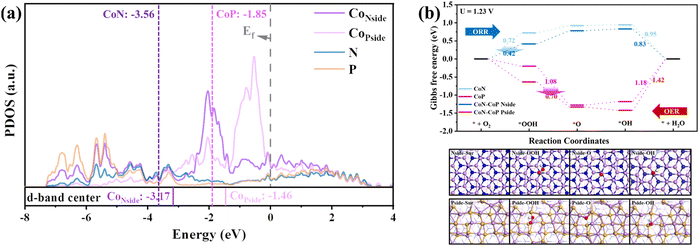
In addition, the essential effects for the ORR and OER improvement on the CoP/CoN heterojunction were determined via DFT calculations (the specific calculation process is shown in the ESI†). The PDOS of CoP/CoN@NCNRs in Fig. 5a reveals that Co, P and N atoms have bonding peaks overlapping between a wide energy window of −7.2–−2.8 eV, proving that CoN and CoP have strong bonding effects to form a stable heterojunction. The d-band center of Co atoms on both the P-side and the N-side increases about 0.4 eV, and the increased d-band center means that the overall d-electron is closer to the Fermi energy and becomes more active to induce electro-reactions, showing that this catalyst has potential for ultra-high ORR and OER performance. The electronic interaction between CoP and CoN also can be noticed in the charge difference snapshot of the CoP–CoN heterojunction, and the electrons of both CoP and CoN sides gather at the junction to form a more stable heterojunction phase. As a result, the two sides are both beneficial for the adsorption of O species due to the loss of electrons.
The ORR and OER pathways shown in Fig. 5b verified the changes in O species adsorption caused by the formation of CoP–CoN heterojunctions. The ORR process occurs on the CoN side, and * + O2 + H+ + e− → *OOH has the highest energy cost (ΔG) of 0.72 eV in the ORR pathway on CoN as the rate-determining step (RDS), restricting its ORR activity. However, on the N-side of the CoP–CoN heterojunction, ΔG for the RDS of the ORR decreases to 0.42 eV due to the strong adsorption of *OOH, significantly enhancing its ORR activity. Similarly, for the P-side, the extra stability of the * OOH state means that the ΔG for the RDS of *O + H2O → *OOH + H+ + e− in the OER process decreases to 0.70 eV, which is 0.38 eV lower than that of CoP, enhancing the OER activity at the same time. The stability regulation of adsorbed intermediate species due to uneven charge distribution in heterojunctions is a vital factor in improving their electrocatalytic performance.51
All the results show that the N-doped carbon-coated heterogeneous structure is favorable for improving the catalytic efficiency. Compared with the comparison samples, CoP/CoN@CNRs/CC displayed better trifunctional catalytic performance. It indicated that the 3D nanorod arrays could provide better electroconductibility and facilitate the exposure of active catalytic sites. On the other hand, the CoP/CoN heterostructural active centers confined on the top of N-doped CNRs can make good use of the structure–function relationship and the rich defect sites, resulting in more efficient catalytic activity and mass transport. Meanwhile, the unique carbon layer protection structure can keep stable during the catalytic test, and the 3D nanorod arrays can be tightly supported by CC with little morphology change. The N-doped carbon layers' excellent protection function can maintain the stability of the internal CoP/CoN particles, resulting in long-term efficient trifunctional catalytic processes. Besides, the in situ self-supported structure of CoP/CoN@CNRs/CC without a binder can be employed on working electrodes, exhibiting the intrinsic activity directly. The flexibility of CC also ensures the potential of the material as a flexible electronic energy source.
3.4. HER test
The HER catalytic activities were assessed with a standard three-electrode system. For comparison, Pt/C, CoP/CC, and Co@NCNRs/CC were examined. The linear sweep voltammetry (LSV) curves (Fig. 6a) at 5 mV s−1 in 1 M KOH without iR-compensation show the polarization curves of CoP/CoN@NCNRs/CC and comparison samples. The overpotential (η) at 10 mA cm−2 is calculated to be ∼165, ∼357, and ∼335 mV for CoP/CoN@NCNRs/CC, Co@NCNRs/CC and CoP/CC, respectively. Compared with the overpotential values of catalysts that have been reported, CoP/CoN@NCNRs/CC shows a lower overpotential value, implying that the catalyst may be an excellent catalyst for the HER (Table S2†). Moreover, Tafel plots are provided in Fig. 6b to compare the HER kinetics of the electrocatalysts with Pt/C. Under alkaline conditions, the typical HER process occurs via the Volmer step and Heyrovsky desorption step. The Tafel slope of the benchmark Pt/C was confirmed to be 120 mV dec−1 under alkaline conditions.52 The measured Tafel slope for CoP/CoN@NCNRs/CC is 118 mV dec−1, smaller than 184 and 207 mV dec−1 of CoP/CC and Co@CNRs/CC and close to the theoretical value of 120 mV dec−1 when the Volmer step [H2O + M + e− ⇌ M–H + OH−] is the rate-limiting step.53,54 | ||
| Fig. 6 Electrochemical testing of the HER and OER: (a) LSV curve of the HER, (b) Tafel slope of the HER, and (c) the chronoamperometric response of the HER. | ||
The electrochemically Active Surface Area (ECSA) of the prepared self-supported samples is shown in Fig. S14 and S15.† The active surface area of the prepared samples was evaluated from the electrochemical double-layer capacitance (Cdl is in proportion to the ECSA). CoP/CoN@NCNRs/CC has the most considerable Cdl (135.0 mF cm−2), superior to 53.6 mF cm−2 of Co@NCNRs/CC and 13.5 mF cm−2 of CoP/CC, indicating more exposed active sites and better catalytic activity of CoP/CoN@NCNRs/CC. The stability of CoP/CoN@NCNRs/CC toward the HER was further confirmed under 20 mA cm−2 current density, and the potential–time plot of CoP/CoN@NCNRS/CC showed no significant change after 30![[thin space (1/6-em)]](https://www.rsc.org/images/entities/char_2009.gif) 000 s of continuous reaction, indicating that CoP/CoN@NCNRS/CC exhibited excellent stability toward the HER (Fig. 6c).
000 s of continuous reaction, indicating that CoP/CoN@NCNRS/CC exhibited excellent stability toward the HER (Fig. 6c).
3.5. Zn–air battery performances
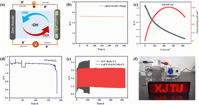
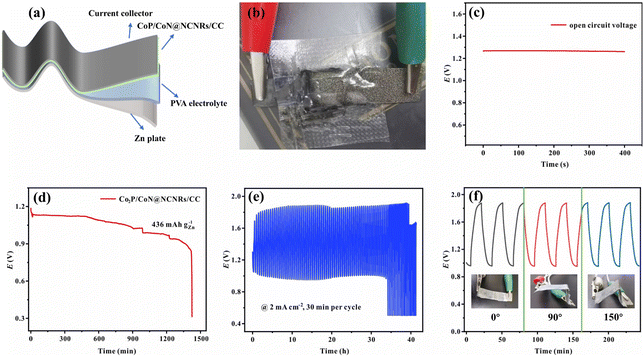
Due to the good trifunctional catalytic activity of CoP/CoN@NCNRs/CC, its potential for application in zinc–air batteries was investigated. The air cathode was made with CoP/CoN@NCNRs/CC, carbon paper and nickel foam (Fig. 7a). The homemade ZAB can work with an open-circuit voltage of 1.515 V (Fig. 7b). The discharge specific capacity (Fig. 7d) of the ZAB is up to 775 mA h g−1 at 10 mA cm−2 and the energy density (Fig. 7c) of the CoP/CoN@NCNRs/CC based ZAB is 120 mW cm−2 at 243.2 mA cm−2. Moreover, the battery life of the as-prepared ZABs was tested at 10 mA cm−2 with 30 min per cycle. The ZABs remained stable without evident decay for 420 h (Fig. 7e), which is much better than that of most electrocatalysts (Table S3†). The single battery can successfully power a LED screen with no significant change in brightness for more than 48 h (Fig. 7f). The result verifies the potential of CoP/CoN@NCNRs/CC for ZAB applications with high discharge current density and long-term stability, which has promising potential for energy conversion configuration.A solid-state sandwich-like layered ZAB was assembled further to explore the potential usage for flexible energy storage devices, with CoP/CoN@NCNRs/CC as the cathode, Zn foil as the anode and a PVA gel-electrolyte (Fig. 8a and b). The flexible all-solid-state ZAB can work at 1.273 V (open-circuit voltage, Fig. 8c) and the corresponding energy density is 63 mW cm−2 (Fig. S16†). Besides, the discharge-specific capacity of the ZAB is up to 556 mA h g−1 at a current density of 2 mA cm−2 (Fig. 8d). In terms of stability, the flexible ZAB can stably run for about 33 h with 0.5 h per charge–discharge cycle at 2 mA cm−2 (Fig. 8e). Fig. 8f exhibits the flexibility of CoP/CoN@NCNRs/CC under different bending conditions. Compared with the original performance, no noticeable change of the voltage gap is observed in discharge and charge curves, indicating that the ZAB can work under external mechanical stress or bending conditions.
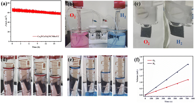
In the water splitting process, CoP/CoN@CNRs/CC as an anode and cathode is tested in 1 M KOH with a two-electrode system. The life test was performed at 1.65 V (Fig. 9a). After a 16 h non-stop test, the current of the whole device changed slightly. As shown in Fig. 9b and c, the amounts of H2 and O2 were measured by the water drainage approach in a H-type electrolytic apparatus to explore the water electrolysis efficiency. The O2 and H2 generation volumes at 0, 3, 6, 9, and 12 min were available from direct measurements (Fig. 9d–f), and the ratio of VO2![[thin space (1/6-em)]](https://www.rsc.org/images/entities/char_2009.gif) :
:![[thin space (1/6-em)]](https://www.rsc.org/images/entities/char_2009.gif) VH2 is identified as about 0.5, indicating that the faradaic efficiency is approximately 100%. These results corroborate the efficiency and durability of CoP/CoN@CNRs/CC for water electrolysis.
VH2 is identified as about 0.5, indicating that the faradaic efficiency is approximately 100%. These results corroborate the efficiency and durability of CoP/CoN@CNRs/CC for water electrolysis.
4. Conclusions
This work describes a new flexible self-supported electrode made of CoP/CoN heterostructural active centers on N-doped carbon nanotube arrays supported by carbon fiber cloth that exhibits efficient trifunctional electroactivity for the HER, OER, and ORR. The overpotential needed to deliver 10 mA cm−2 is determined to be ∼165 mV for the HER and ∼234 mV for the OER in 1.0 M KOH. In addition, the E1/2 is 0.86 V vs. RHE, and the diffusion-limiting current density is ∼4.0 mA cm−2 for the ORR in 0.1 M KOH. Besides, it exhibits good electrochemical stability in these catalytic processes. From the mechanism analysis can be drawn that Co–Nx–C sites were responsible for the efficient OER and ORR, while Co–P sites might react in the OER and HER. DFT calculations show that the electrons of both CoP and CoN sides gather at the junction to form a more stable heterojunction phase, and the two sides are both beneficial for the adsorption of O species due to the loss of electrons, which is consistent with the experimental mechanism for O species adsorption. The stability regulation of adsorbed intermediate species due to uneven charge distribution in heterojunctions is a vital factor in improving their electrocatalytic performance. For application, CoP/CoN@NCNRs/CC exhibits outstanding cycling charge/discharge stability and performs for more than 420 h, along with commendable flexibility in ZABs and low overpotential in water splitting, showing the potential to exploit advanced transition metal-based hybrid trifunctional catalysts for electrocatalytic applications, especially in new energy devices and flexible electronics.Author contributions
Linmng Bai: conceptualization, methodology, investigation, and writing – original draft. Dan Wang: formal analysis and writing – review & editing. Hongchen Shen: writing – review & editing. Wenlong Wang: formal analysis and writing – review & editing. Shanshan Li: supervision. Wei Yan: supervision and writing – review & editing.Conflicts of interest
The authors declare no conflict of interest.Acknowledgements
This work was supported by the National Natural Science Foundation of China (Grant No. 51978569). The authors gratefully acknowledge the support of the Instrument Analysis Center of Xi'an Jiaotong University.Notes and references
- J. A. Turner, Science, 2004, 305, 972–974 CrossRef CAS PubMed.
- J. Zhou, J. Cheng, B. Wang, H. Peng and J. Lu, Energy Environ. Sci., 2020, 13, 1933–1970 RSC.
- M. A. Mushtaq, M. Arif, X. Fang, G. Yasin, W. Ye, M. Basharat, B. Zhou, S. Yang, S. Ji and D. Yan, J. Mater. Chem. A, 2021, 9, 2742–2753 RSC.
- G. Zhou, G. Liu, X. Liu, Q. Yu, H. Mao, Z. Xiao and L. Wang, Adv. Funct. Mater., 2021, 32, 2107608 CrossRef.
- S. Yang, Y. Zhu, N. Chen, J. Huang, H. Cai and Y. Han, et al. , Appl. Catal., B, 2022, 304, 120914 CrossRef CAS.
- S. Chae, A. Muthurasu, T. Kim, J. Kim, M. Khil, M. Lee, H. Kim, J. Lee and H. Kim, Appl. Catal., B, 2021, 293, 120209 CrossRef CAS.
- A. Wang, C. Zhao, M. Yu and W. Wang, Appl. Catal., B, 2021, 281, 119514 CrossRef CAS.
- M. Wang, K. Su, M. Zhang, X. Du and Z. Li, ACS Sustain. Chem. Eng., 2021, 9, 13324–13336 CrossRef CAS.
- L. Zhang, Y. Zhu, Z. Nie, Z. Li, Y. Ye, L. Li, J. Hong, Z. Bi, Y. Zhou and G. Hu, ACS Nano, 2021, 15, 13399–13414 CrossRef CAS PubMed.
- J. Liu, J. Zhou and M. K. H. Leung, ACS Appl. Mater. Interfaces, 2022, 14, 4399–4408 CrossRef CAS PubMed.
- M. Xie, Y. Zhou, Z. Wang, H. Wang, D. Yan, B. Han, S. Zhang and C. Deng, Chem. Eng. J., 2022, 431, 133920 CrossRef CAS.
- A. Muthurasu, A. P. Tiwari, K. Chhetri, B. Dahal and H. Y. Kim, Nano Energy, 2021, 88, 106238 CrossRef CAS.
- H. Wang, C. Tang and Q. Zhang, Adv. Funct. Mater., 2018, 28, 1803329 CrossRef.
- Y. Li and H. Dai, Chem. Soc. Rev., 2014, 43, 5257–5275 RSC.
- J. Zhang, Q. Zhou, Y. Tang, L. Zhang and Y. Li, Chem. Sci., 2019, 10, 8924–8929 RSC.
- Q. Zhou, J. Cai, Z. Zhang, R. Gao, B. Chen, G. Wen, L. Zhao, Y. Deng, H. Dou, X. Gong, Y. Zhang, Y. Hu, A. Yu, X. Sui, Z. Wang and Z. Chen, Small Methods, 2021, 5, e2100024 CrossRef PubMed.
- Z. Li, G. Jiang, Y. P. Deng, G. Liu, D. Ren, Z. Zhang, J. Zhu, R. Gao, Y. Jiang, D. Luo, Y. Zhu, D. H. Liu, A. M. Jauhar, H. Jin, Y. Hu, S. Wang and Z. Chen, iScience, 2020, 23, 101404 CrossRef CAS PubMed.
- X. Fu, G. Jiang, G. Wen, R. Gao, S. Li, M. Li, J. Zhu, Y. Zheng, Z. Li, Y. Hu, L. Yang, Z. Bai, A. Yu and Z. Chen, Appl. Catal., B, 2021, 293, 120176 CrossRef CAS.
- D. Deng, J. Qian, X. Liu, H. Li, D. Su, H. Li, H. Li and L. Xu, Adv. Funct. Mater., 2022, 32, 2203471 CrossRef CAS.
- X. Ao, Y. Ding, G. Nam, L. Soule, P. Jing, B. Zhao, J. Y. Hwang, J. H. Jang, C. Wang and M. Liu, Small, 2022, 18, e2203326 CrossRef PubMed.
- S. Li, M. Qi, Z. Tang and Y. Xu, Chem. Soc. Rev., 2021, 50, 7539–7586 RSC.
- M. Zhuang, X. Ou, Y. Dou, L. Zhang, Q. Zhang, R. Wu, Y. Ding, M. Shao and Z. Luo, Nano Lett., 2016, 16, 4691–4698 CrossRef CAS PubMed.
- J. Kibsgaard, C. Tsai, K. Chan, J. D. Benck, J. K. Nørskov, F. Abild-Pedersen and T. F. Jaramillo, Energy Environ. Sci., 2015, 8, 3022–3029 RSC.
- X. Tang, N. Li and H. Pang, Green Energy Environ., 2022, 7, 636–661 CrossRef CAS.
- Y. Li, J. Fu, C. Zhong, T. Wu, Z. Chen, W. Hu, K. Amine and J. Lu, Adv. Energy Mater., 2018, 9, 1802605 CrossRef.
- M. Luo, W. Sun, B. B. Xu, H. Pan and Y. Jiang, Adv. Energy Mater., 2020, 11, 2002762 CrossRef.
- X. Liu, X. Fan, B. Liu, J. Ding, Y. Deng, X. Han, C. Zhong and W. Hu, Adv. Mater., 2021, 33, e2006461 CrossRef PubMed.
- K. Song, B. Yang, Z. Li, Y. Lv, Y. Yu, L. Yuan, X. Shen and X. Hu, Appl. Surf. Sci., 2020, 529, 147064 CrossRef CAS.
- M. Li, S. Chen, B. Li, Y. Huang, X. Lv, P. Sun, L. Fang and X. Sun, Electrochim. Acta, 2021, 388, 138587 CrossRef CAS.
- Y. Guo, P. Yuan, J. Zhang, H. Xia, F. Cheng, M. Zhou, J. Li, Y. Qiao, S. Mu and Q. Xu, Adv. Funct. Mater., 2018, 28, 1805641 CrossRef.
- C. Su, H. Cheng, W. Li, Z. Liu, N. Li, Z. Hou, F. Bai, H. Zhang and T. Ma, Adv. Energy Mater., 2017, 7, 1602420 CrossRef.
- M. Wang, S. Liu, N. Xu, T. Qian and C. Yan, Adv. Sustainable Syst., 2017, 1, 1700085 CrossRef.
- Z. Han, J. J. Feng, Y. Q. Yao, Z. G. Wang, L. Zhang and A. J. Wang, J. Colloid Interface Sci., 2021, 590, 330–340 CrossRef CAS PubMed.
- Z. Han, J. Feng, Y. Yao, Z. Wang, L. Zhang and A. Wang, J. Colloid Interface Sci., 2021, 590, 330–340 CrossRef CAS PubMed.
- L. Ma, S. Chen, Z. Pei, H. Li, Z. Wang, Z. Liu, Z. Tang, J. A. Zapien and C. Zhi, ACS Nano, 2018, 12, 8597–8605 CrossRef CAS PubMed.
- S. M. Alshehri, A. N. Alhabarah, J. Ahmed, M. Naushad and T. Ahamad, An efficient and cost-effective tri-functional electrocatalyst based on cobalt ferrite embedded nitrogen doped carbon, J. Colloid Interface Sci., 2018, 514, 1–9 CrossRef CAS PubMed.
- S. M. Alshehri, A. N. Alhabarah, J. Ahmed, M. Naushad and T. Ahamad, J. Colloid Interface Sci., 2018, 514, 1–9 CrossRef CAS PubMed.
- Y. Zhang, W. Shi, L. Bo, Y. Shen, X. Ji, L. Xia, X. Guan, Y. Wang and J. Tong, Chem. Eng. J., 2022, 431, 134188 CrossRef CAS.
- A. Samanta, A. Ghatak, S. Bhattacharyya and C. R. Raj, Electrochim. Acta, 2020, 348, 136274 CrossRef CAS.
- R. Yang, J. Catal., 1989, 115, 52–64 CrossRef CAS.
- A. Sumboja, T. An, H. Y. Goh, D. P. Howard, Y. J. Xu, A. D. Handoko, Y. Zong and Z. L. Liu, ACS Appl. Mater. Interfaces, 2018, 10, 15673–15680 CrossRef CAS PubMed.
- Y. L. Niu, S. Q. Gong, X. Liu, C. Xu, M. Z. Xu, S. G. Sun and Z. F. Chen, Escience, 2022, 2, 546–556 CrossRef.
- H. Liu, J. Guan, S. Yang, Y. Yu, R. Shao, Z. Zhang, M. Dou, F. Wang and Q. Xu, Adv. Mater., 2020, 32, e2003649 CrossRef PubMed.
- W. Tian, J. Ren and Z. Yuan, Appl. Catal., B, 2022, 317, 121764 CrossRef CAS.
- S. Yang, J. Y. Zhu, X. N. Chen, M. J. Huang, S. H. Cai and J. Y. Han, et al. , Appl. Catal., B, 2022, 304, 120914 CrossRef CAS.
- K. M. Zhao, S. Liu, Y. Y. Li, X. Wei, G. Ye, W. Zhu, Y. Su, J. Wang, H. Liu, Z. He, Z. Y. Zhou and S. G. Sun, Adv. Energy Mater., 2022, 12, 2103588 CrossRef CAS.
- Y. Zhang, J. Xu, Y. Ding and C. Wang, Int. J. Hydrogen Energy, 2020, 45, 17388–17397 CrossRef CAS.
- J. Zhang, L. Ji, J. Gong and Z. Wang, Phys. Chem. Chem. Phys., 2022, 24, 13839–13847 RSC.
- D. J. Deng, J. C. Qian, X. Z. Liu, H. P. Li, D. Su and H. N. Li, et al. , Adv. Funct. Mater., 2022, 32, 2203471 CrossRef CAS.
- W. Ni, T. Wang, F. Heroguel, A. Krammer, S. Lee, L. Yao, A. Schuler, J. S. Luterbacher, Y. Yan and X. Hu, Nat. Mater., 2022, 21, 804–810 CrossRef CAS PubMed.
- H. G. Li, S. L. Di, P. Niu, S. L. Wang, J. Wang and L. Li, Energy Environ. Sci., 2022, 15, 1601–1610 RSC.
- A. Kahyarian, B. Brown and S. Nesic, J. Electrochem. Soc., 2017, 164, H365–H374 CrossRef CAS.
- S. Fletcher, J. Solid State Electrochem., 2008, 13, 537–549 CrossRef.
- T. Shinagawa, A. T. Garcia-Esparza and K. Takanabe, Sci. Rep., 2015, 5, 13801 CrossRef PubMed.
Footnote |
| † Electronic supplementary information (ESI) available. See DOI: https://doi.org/10.1039/d3ta06935d |
| This journal is © The Royal Society of Chemistry 2024 |

