In situ construction of polyether-based composite electrolyte with bi-phase ion conductivity and stable electrolyte/electrode interphase for solid-state lithium metal batteries†
Shujun
Zheng
a,
Yuyang
Chen
a,
Kai
Chen
a,
Shengyuan
Yang
 a,
Roohollah
Bagherzadeh
 c,
Yue-E
Miao
 *a and
Tianxi
Liu
ab
aState Key Laboratory for Modification of Chemical Fibers and Polymer Materials, College of Materials Science and Engineering, Donghua University, Shanghai, 201620, China. E-mail: yuee_miao@dhu.edu.cn
bKey Laboratory of Synthetic and Biological Colloids, Ministry of Education, School of Chemical and Material Engineering, Jiangnan University, Wuxi, 214122, China
cAdvanced Fibrous Materials LAB, Institute for Advanced Textile Materials and Technologies (ATMT), School of Advanced Materials and Processes, Amirkabir University of Technology, Tehran, Iran
First published on 26th May 2022
Abstract
Polyether-based composite electrolytes exhibit great promise to bridge the gap between solid polymer electrolytes (SPEs) and high-energy solid-state Li metal batteries. However, the practical application of polyether electrolytes is still hindered by their poor ionic conductivity and low oxidation potential. Herein, a topochemistry-driven polyether-based composite electrolyte is constructed in situ, by the cation polymerization of 1,3-dioxolane (DOL) to obtain poly(1,3-dioxolane) (PDOL) in a three-dimensional (3D) La0.56Li0.33TiO3 nanofiber (LLTO NF) skeleton, with a chemically stable interface and strong-coupled ionic conductivity. The spontaneous polymerization reaction results in the formation of a unique polymeric CH2–CH2–O–CH2–O– amorphous structure of PDOL, with a wide operation voltage (5.5 V) and an intimate interface within the LLTO NF skeleton. The continuous one-dimensional (1D) LLTO NFs and polymer chains act as bi-phase ion transport channels, enabling an improved conduction of 6.6 × 10⁻⁴ S cm−1. Furthermore, the LiF and Al-complex films derived from the solid electrolyte interphase (SEI) can redistribute the ion flux and ensure the structural stability of the Li anode. Thus, the polyether-based composite electrolyte achieves a remarkable cyclability (over 900 h at 0.1 mA cm−2) and satisfactory capacity retention (70.7% over 350 cycles). This polymer composite electrolyte design offers a unique perspective for linking in situ topochemistry design with safe and high-energy solid batteries.
Introduction
Triggered by the increasing demand for technologies ranging from flexible electronics and electric vehicles to electrical grids,1–3 there is an urgent need for a breakthrough in electrochemical energy storage systems. The lithium (Li) metal anode is a very promising candidate for high-energy lithium metal batteries (LMBs), due to its high specific capacity (3860 mA h g−1) and ultra-low redox potential (−3.04 V vs. standard hydrogen electrode).4–6 However, it suffers from uncontrollable dendritic growth, electrolyte corrosion, and thermodynamic instability in liquid LMBs.7,8 Developing solid-state electrolytes (SSEs) can overcome the above hindrances while also achieving improved security.Among existing SSEs, solid polymer electrolytes (SPEs) stand out for their superior flexibility, designability and intimate interfacial contact.9–11 However, the traditional polyethylene oxide (PEO) electrolyte, one of the main commercial electrolytes, faces many obstacles, including insufficient ionic conduction (10−6 to 10−8 S cm−1, at room temperature) and a low oxidation potential (3.8 V vs. Li/Li+).12–14 Composite polymer electrolytes (CPEs) can bridge the above gaps by integrating active inorganic fillers into polyether electrolytes.15–17 The rigid inorganic fillers in CPEs, with their inherent high ion conductivity, play a critical role in suppressing the agglomeration of polymer chains and accelerating the dissociation of Li salt.18,19 Moreover, flexible macromolecular chains are effective for optimizing the electrode–electrolyte interface, providing efficient intermolecular/intramolecular Li-ion migration.20–22 Nevertheless, it is still a great challenge to selectively design flexible-rigid integrated CPEs to realize superior conductivity and interface compatibility simultaneously for maximized long-term cyclability of solid metal batteries.
Herein, we propose a rational topochemistry-driven polymerization tactic for the construction of a bi-phase ion conductive polyether-based composite electrolyte with a chemically stable interphase. The composite electrolyte is prepared by the cationic polymerization of 1,3-dioxolane (DOL) to obtain poly(1,3-dioxolane) (PDOL) in a self-supporting La0.56Li0.33TiO3 nanofiber (LLTO NF) framework, which is denoted as In-situ PLE. The topochemistry design endows the polyether-based composite electrolyte with remarkable merits: (i) the unique amorphous structure of the CH2–CH2–O–CH2–O– chain in PDOL obtained by in situ polymerization ensures intimate electrode/electrolyte interfacial contact, which allows for fast bulk/interfacial transfers and a broadened voltage window; (ii) the rich LiF and Al-complex solid electrolyte interphase (SEI) can serve as an ionic rectifier layer to redistribute ion flux, thereby reducing the accumulation of dead Li and inhibiting dendritic growth; (iii) the 1D–1D interconnected interface between PDOL polymer chains and LLTO NFs can offer highly efficient bi-phase transport pathways. Therefore, the In-situ PLE achieves a dense, dendrite-free Li circulating layer over 900 h and a largely improved long-term cyclability of 70.7% over 350 cycles at 0.5C.
Results and discussion
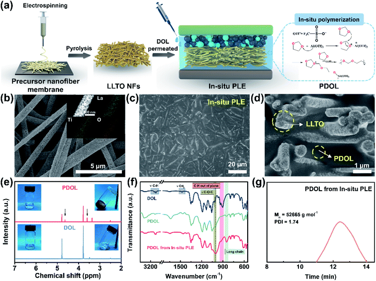
The composite polyether electrolyte containing PDOL and LLTO NFs is denoted as PLE. Under an in situ polymerization condition of DOL, as illustrated in Fig. 1a, the as-prepared sample is the In-situ PLE. For comparison, PLE obtained under an ex situ polymerization of DOL is denoted as Ex-situ PLE, while the PDOL electrolyte without LLTO NFs is also prepared via in situ polymerization as a control sample. Typically, LiTFSI is added to all electrolytes, but they are ignored in the naming. First, the self-supporting LLTO NF skeleton was obtained by a simple electrospinning-sintering method.23Fig. 1b and S1a† shows continuous porous LLTO nanofibers with a diameter of ∼500 nm, derived from the flexible precursor nanofiber membrane with a uniform fiber diameter of 570 nm and concentrated pore size of 1.48 μm (Fig. S2†), forming a three-dimensional (3D) skeleton structure. A high specific surface area of 35.685 m2 g−1 with a mesoporous pore size of 15.84 nm is obtained for the LLTO NFs (Fig. S3†). The inset in Fig. 1b confirms the homogenous distribution of La, Ti, and O elements. These results suggest that the interconnected and porous structure of the ceramic LLTO electrolyte is advantageous for continuous ion conduction. In addition, a clear lattice spacing of 2.7 Å corresponding to the (110) plane of the LLTO crystal can be observed in Fig. S1b and S1c,†24 confirming its high crystallinity and that the fastest ion transfer occurs along the [001] direction.25Subsequently, the DOL solution was allowed to permeate into the LLTO skeleton, and the cation ring-opening polymerization was completed within 12 h.26,27 To construct a thin ion-conductive skeleton, the thickness of the LLTO NF matrix was controlled to be 150 μm. As shown in Fig. 1c, a smooth and flat solid structure is acquired after introducing the pre-polymerized precursor into the LLTO NF matrix. The final thickness of the In-situ PLE remains at 144 μm, as shown in the typical cross-sectional scanning electron microscope (SEM) image (Fig. S4†). It is clear that the LLTO NFs are completely covered by PDOL without obvious pores in Fig. 1d, demonstrating that the precursor solution is uniformly filled into the porous LLTO NF matrix and gradually forms a polymer network. This suggests the formation of a dense bi-phase ion conduction network, where the LLTO NF skeleton acts as a 3D continuous Li-ion transport channel. Meanwhile, the PDOL phase permeated in LLTO can achieve rapid ion conduction through the coupling/decoupling of O and Li+ in the –CH2–CH2–O–CH2–O– polymer chains.13,28
To further analyze the topochemistry of PDOL, nuclear magnetic resonance (NMR) measurements were performed (Fig. 1e). Obviously, the pristine liquid DOL electrolyte was transformed into a transparent solid polyether electrolyte after adding a small dose of Al(OTf)3. Al3+ attacked the oxygen atoms in DOL, causing the ring-opening polymerization,29 while two new signals at 3.61 ppm and 4.64 ppm are ascribed to proton peaks from the –O–CH2–CH2– and –O–CH2–O– groups, respectively, which agrees well with the repeating unit of –CH2–CH2–O–CH2–O– in PDOL.27 It is worth mentioning that the bare DOL electrolyte without Lewis-acid additives shows no obvious change. Then, Fourier transform infrared spectroscopy (FTIR) was conducted to discern the changes in the molecular structure during the polymerization process of the In-situ PLE (Fig. 1f). After curing for 12 h, the out-of-plane C–H vibration peak disappears, and the peak position of C–O–C shifts from 1030 cm−1 to 1000 cm−1, along with the appearance of a long-chain structure belonging to PDOL.26 The conspicuous changes of these characteristic peaks confirm the successful polymerization of PDOL. In addition, the FTIR spectrum of PDOL obtained from the In-situ PLE is consistent with that of pure PDOL, indicating that the cationic polymerization process of DOL is not affected by the LLTO NFs. Furthermore, the final molecular weight of PDOL was measured to be 52![[thin space (1/6-em)]](https://www.rsc.org/images/entities/char_2009.gif) 665 g mol−1 from the gel permeation chromatography (GPC) result (Fig. 1g).
665 g mol−1 from the gel permeation chromatography (GPC) result (Fig. 1g).
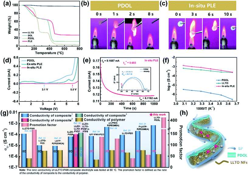
The physicochemical and electrochemical properties of the In-situ PLE were then systematically examined. As shown in Fig. 2a, the liquid DOL begins to volatilize at 30 °C, whereas the PDOL electrolyte shows a significantly improved thermal stability with a decomposition temperature up to 100 °C. The weight loss of all the electrolytes at about 400 °C is due to the thermolysis of LiTFSI.26 No mass loss is observed throughout the pyrolysis process of LLTO NFs, indicating its excellent thermal stability.30 Direct evidence can also be provided by the combustion experiments shown in Fig. 2b and c. A fast and short burn-out process is observed for the PDOL electrolyte with a duration of 8 s (Video S1†), which can be ascribed to the remaining DOL solvent and the low melting point of PDOL. Surprisingly, the In-situ PLE, in combination with the highly flame-retardant LLTO NF matrix, displays satisfactory self-extinguishing characteristics and maintains structural integrity, even if it burns within the first few seconds (Video S2†). This is in contrast to the severe thermal melting presented in a commercial Celgard separator (Fig. S5 and video S3†).
Apart from the good flame retardancy, the In-situ PLE also exhibits excellent electrochemical properties. Although the PEO electrolyte is stable in combination with the Li anode, the narrow window of only 4.1 V limits its practical applications. With the novel polyether of PDOL obtained by an in situ topochemistry design, the electrochemical window of the In-situ PLE can be expanded to 5.5 V (Fig. 2d), which is suitable for almost all commercial cathode materials. Importantly, an ion migration number of 0.6 can be reached (Fig. 2e and S6†), which significantly exceeds that of the traditional PEO electrolyte (tLi+ = 0.2).13,31 This can be attributed to the fact that the continuous functional –C–O– groups in the PDOL network can provide unique ion coordination for Li+ and accelerate ion migration. Considering that the conductivity of SPE is in connection with its amorphous state and the free volume from rubber to viscoelastic state above the glass transition temperature (Tg), differential scanning calorimeter (DSC) tests were carried out to study the thermal behavior of PDOL. Fig. S7† shows the crystalline structure for the salt-free PDOL, in which a large melting peak (Tm) and recrystallization peak can be observed, while the PDOL-LiTFSI electrolyte presents an amorphous state with only a Tg point due to the plasticizing effect.29 Further evidence can be estimated by the activation energy (Ea) of Li+ migration in Fig. 2f. The value (0.165 eV) for the In-situ PLE is much lower than those of the PDOL (0.363 eV) and LLTO electrolytes (0.255 eV). Moreover, the room-temperature Li+ conductivity obtained in this work is 6.6 × 10⁻⁴ S cm−1, which is much higher than those of most previous studies (Fig. 2g).21,23,24,30,32–34 This can be attributed to the inherent amorphous structure and low Tg point of PDOL, as well as the continuous 3D Li+ transfer channels in LLTO NFs (Fig. 2h). Taken together, the superior self-extinguishing, wide voltage windows, and rapid bi-phase ion conductive paths not only make up for the two major shortcomings of traditional polyether electrolytes, but also suggest great potential for solid batteries with long-term cyclability.
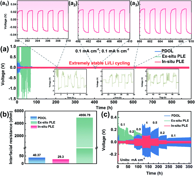
In situ polymerization is deemed as the most universal solution to improve interfacial compatibility. As shown in Fig. 3a, three types of electrolytes were extended into symmetric cells to evaluate the voltage polarization phenomenon and long-term cycling stability. The Li|Ex-situ PLE|Li cell shows a sharply increased polarization voltage over 2 V in just a few minutes, together with a heavier voltage fluctuation and battery failure (inset in Fig. 3a) at a constant current density of 0.1 mA cm−2. Meanwhile, the cell with the PDOL electrolyte displays a smaller overpotential than that of the Ex-situ PLE-based symmetric cell, which undergoes continuous and unstable fluctuations and causes a short circuit at 100 h. In contrast, the Li|In-situ PLE|Li cell displays superior cycling stability for over 900 h with a stable overpotential of ∼40 mV. The enlarged voltage profiles after different times also show no significant polarization for the In-situ PLE prepared via in situ polymerization (Fig. 3a1–a3). The current density further improved to 0.5 mA cm−2, and the In-situ PLE remains stable at about 280 mV for 400 h (Fig. S8†). We determined that the excellent long-term interfacial stability derived from the high ionic conductivity of the In-situ PLE and the in situ improved electrode–electrolyte interfacial compatibility. The interfacial stability of the Li|In-situ PLE|Li cell was further substantiated by electrochemical impedance spectra (EIS) tests (Fig. 3b, S9 and S10†). Obviously, the interfacial impedance (Rct) of the Li|Ex-situ PLE|Li cell is about 4957 Ω, which is 100 times than that (40.37 Ω) of the Li|PDOL|Li cell. We can infer that the extremely high Rct of the Ex-situ PLE derived from rigid ion transport at the solid–solid interface would lead to large amounts of dead lithium and rapid cell failure. Meanwhile, the Li|PDOL|Li cell with low Rct can maintain normal circulation but is hindered by the poor mechanical properties of the PDOL electrolyte. On the contrary, the Li|In-situ PLE|Li cell presents a very low initial Rct of only 29.3 Ω and remains stable without any obvious increase after 300th cycling, which is consistent with the Li-plating/stripping curves.
Aside from interfacial wettability and conductivity, symmetric batteries were also conducted to evaluate the Li+ transmission rate (Fig. 3c). By constantly changing the current density to different values (0.1, 0.2, 0.5, 1, 0.5, 0.2 to 0.1 mA cm−2), the In-situ PLE symmetric cell shows the lowest polarization voltages of 40, 60, 92, 182, 110, 56 and 32 mV, respectively. The overpotential of In-situ PLE presents some fluctuations in the first 3 h, probably because of the formation of SEI. Even under high variation rates, it maintains stable cycling without polarization or short circuit phenomena. In contrast, the Li|Ex-situ PLE|Li cell exhibits an asymmetrical electrochemical curve due to its high interfacial transport barrier (Fig. 3b) and lithium dendrites form inside the Ex-situ PLE skeleton when the potential reaches <0 V versus Li/Li+.30 This is directly supported by the X-ray photoelectron spectroscopy (XPS) analyses in Fig. S11.† Compared with the white LLTO NFs in the Li|In-situ PLE|Li cell, the LLTO NFs in the Li|Ex-situ PLE|Li cell present the black color with the existence of oxygen vacancies (Fig. S11a–c†). The appearance of peaks corresponding to Ti3+ further prove the electrochemical instability of the Ex-situ PLE (Fig. S11d†).30
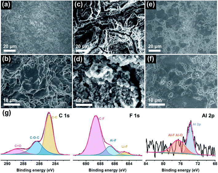
To elucidate the reasons behind long-cycle stability, the surface features and chemical compositions of the Li anode were evaluated by ex situ SEM and XPS measurements after cycling. Fig. 4a–f presents the top-view SEM images of the cycled Li electrode at low and high magnifications. Evidently, there are many chaotic clusters unevenly distributed on the anode surface in the PDOL-based battery (Fig. 4a and b). These bulk and loose Li clusters will evolve into dendrites in subsequent cycles, which is deemed to be the foremost reason for the sudden short circuit of the corresponding cell at 80 h, as shown in Fig. 3a. Further, the Ex-situ PLE symmetric cell displays a rugged Li surface with lots of scratches and cracks, and metallic particles appear at higher magnification (Fig. 4c and d). The harsh structural failure indicates the disordered Li electrodeposition behavior on the Li anode, which reveals unstable Li plating/stripping kinetics. In sharp contrast, the anode surface in the Li|In-situ PLE|Li cell after cycling is flat and dense without obvious defects (Fig. 4e and f), which contributes to the sturdy mechanical and sustainable chemical behaviors of the composite polyether electrolyte, and ensures the long circulation of the symmetric cell. Moreover, XPS analysis further investigates the chemical state of the SEI on the Li metal anode in In-situ PLE. As shown in Fig. 4g, the main peaks of the C 1s spectrum come from the polymer chain. Due to the electrochemical decomposition of N(CF3SO2)2− (TFSI−) anions on the anode surface, an obvious signal of LiF is detected, implying that a LiF-rich SEI film is formed, which is known as an electric insulator with a low activation energy barrier for Li diffusion to stabilize the electrode/electrolyte interface.35–38 Simultaneously, an Al signal from residual Al(OTf)3 is also detected (Fig. S12†). The Al–F and Al–O species generated from the Al(OTf)3 decomposition participate in the construction of SEI, in which the aluminum complex (AlF3 and Al2O3) contribute to the reduced energy of lithium salt dissociation and act as an anodic protective film, respectively. It is also beneficial for the formation of a stable and robust SEI, thus enhancing the stability of the Li metal anode.29,39,40 The above results confirm the excellent effects of the In-situ PLE in interfacial passivation and the inhibition of dendrite growth.
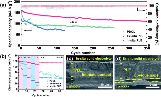
Inspired by the high oxidation features of the designed In-situ PLE, full batteries composed of LiFePO4 (LFP) cathode and solid electrolytes were further evaluated to assess its practical compatibility (Fig. 5a). The Li|PDOL|LFP full battery exhibits a huge capacity fluctuation in the first 25 cycles, and a steep drop from 121.6 to 92.9 mA h g−1 along with high polarization voltage after 95 cycles (Fig. S13†). Similarly, the Li|Ex-situ PLE|LFP delivers an initial discharge capacity of 118.8 mA h g−1 and drops to 69.4 mA h g−1 with unsatisfactory retention of only 57.6% after 120 cycles. Surprisingly, the Li|In-situ PLE|LFP full battery achieves an enhanced specific capacity of 157.6 mA h g−1 and can still reach up to 70.7% after 350 cycles with an average CE of 99.9%. Fig. 5b shows the rate stability from 0.1C to 2C, where the PDOL-assembled battery is reduced from 156.3 to 105.8 mA h g−1 after 5 cycles, and finally reaches 59.2 mA h g−1 when recovered to 0.5C. This can be traced to the inherent weak mechanical resistance and low conductivity of the PDOL. The battery assembled with Ex-situ PLE also presents inferior capacity maintenance under various current rates. Most notably, the Li|In-situ PLE|LFP full battery delivers high discharge capacities of 149, 146.6, 143.5, 139 and 132.8 mA h g−1 at 0.1, 0.2, 0.5, 1 and 2C, respectively. It is worth mentioning that when the current rate is recovered to 0.5C, the capacity remains at 142.5 mA h g−1, further indicating the superior reversible rate capability. This can be ascribed to the excellent interfacial ion transport and high bulk ion conduction of the In-situ PLE assembled battery, with a continuous interface between the In-situ PLE and LFP cathode compared to the clear gaps between the Ex-situ PLE and LFP cathode (Fig. 5c and d).
Conclusions
In summary, a topochemistry-driven polyether electrolyte is incorporated into the 3D fast ion conductor of LLTO NF skeleton via in situ polymerization, which synergistically addresses the chemical/electrochemical interfacial instability, low ionic conductivity, and poor cyclability of solid lithium metal batteries. The unique amorphous structure of CH2–CH2–O–CH2–O– in PDOL effectively promotes bulk and interfacial ion transfer, contributing to a wide window of 5.5 V and tLi+ of 0.6. Moreover, the generated LiF and Al-complex film can also hinder dendrite growth and the formation of dead Li. Arising from bi-phase transport paths, the polyether-based composite electrolyte exhibits a comparatively high σ of 6.6 × 10⁻⁴ S cm−1. Therefore, the Li metal anode with In-situ PLE can stably work at high rates for over 900 h without dendrite growth. The assembled LMBs with LFP cathode show a high capacity retention of 70.7% after 350 cycles at 0.5C, with a satisfactory coulombic efficiency of 99.9%.Conflicts of interest
There are no conflicts to declare.Acknowledgements
This project was funded by the National Natural Science Foundation of China (22075042), Shanghai Rising-Star Program (22QA1400300), the Natural Science Foundation of Shanghai (20ZR1401400), the Fundamental Research Funds for the Central Universities and the DHU Distinguished Young Professor Program (LZB2021002).Notes and references
- K. J. Kim, M. Balaish, M. Wadaguchi, L. Kong and J. L. M. Rupp, Adv. Energy Mater., 2021, 11, 2002689 CrossRef CAS.
- C. Ma, C. Liu, Y. Zhang, X. Zhang, Z. Zhao, T. Song, B. Wu and D. Mu, Chem. Eng. J., 2022, 434, 134637 CrossRef CAS.
- G. Li, Adv. Energy Mater., 2021, 11, 2002891 CrossRef CAS.
- F. Shi, C. Chen and Z. L. Xu, Adv. Fiber Mater., 2021, 3, 275–301 CrossRef CAS.
- X. R. Chen, B. C. Zhao, C. Yan and Q. Zhang, Adv. Mater., 2021, 33, 2004128 CrossRef CAS PubMed.
- Y. Y. Chen, G. Y. Zhou, W. Zong, Y. Ouyang, K. Chen, Y. Lv, Y. E. Miao and T. X. Liu, Compos. Commun., 2021, 25, 100679 CrossRef.
- H. J. Kim, N. Umirov, J. S. Park, J. H. Lim, J. Zhu, S. S. Kim and S. T. Myung, Energy Storage Mater., 2022, 46, 76–89 CrossRef.
- C. Y. Zhou, W. Zong, G. Y. Zhou, X. S. Fan and Y. E. Miao, Compos. Commun., 2021, 25, 100696 CrossRef.
- Y. Ren and K. B. Hatzell, J. Mater. Chem. A, 2021, 9, 13804–13821 RSC.
- P. Ding, Z. Lin, X. Guo, L. Wu, Y. Wang, H. Guo, L. Li and H. Yu, Mater. Today, 2021, 51, 449–474 CrossRef CAS.
- C. Zhao, X. Yao, H. Yang, X. Jiao and L. Wang, Compos. Commun., 2021, 26, 100789 CrossRef.
- K. Jiang, J. Wang, C. Zuo, S. Li, S. Li, D. He, H. Peng, X. Xie, R. Poli and Z. Xue, Macromolecules, 2020, 53, 7450–7459 CrossRef CAS.
- K. Zhang, F. Wu, X. Wang, L. Zheng, X. Yang, H. Zhao, Y. Sun, W. Zhao, Y. Bai and C. Wu, Adv. Funct. Mater., 2022, 2107764 CrossRef CAS.
- H. He, Y. Chai, X. Zhang, P. Shi, J. Fan, Q. Xu and Y. Min, J. Mater. Chem. A, 2021, 9, 9214–9227 RSC.
- J. Zhang, X. Zang, H. Wen, T. Dong, J. Chai, Y. Li, B. Chen, J. Zhao, S. Dong, J. Ma, L. Yue, Z. Liu, X. Guo, G. Cui and L. Chen, J. Mater. Chem. A, 2017, 5, 4940–4948 RSC.
- T. Dong, J. Zhang, G. Xu, J. Chai, H. Du, L. Wang, H. Wen, X. Zang, A. Du, Q. Jia, X. Zhou and G. Cui, Energy Environ. Sci., 2018, 11, 1197–1203 RSC.
- Q. Wang, T. Dong, Q. Zhou, Z. Cui, X. Shangguan, C. Lu, Z. Lv, K. Chen, L. Huang, H. Zhang and G. Cui, Sci. China Chem., 2022, 65, 934–942 CrossRef CAS.
- Z. Geng, Y. Huang, G. Sun, R. Chen, W. Cao, J. Zheng and H. Li, Nano Energy, 2021, 91, 106679 CrossRef.
- Z. Shen, Y. Cheng, S. Sun, X. Ke, L. Liu and Z. Shi, Carbon Energy, 2021, 3, 482–508 CrossRef CAS.
- J. Pan, H. Peng, Y. Yan, Y. Bai, J. Yang, N. Wang, S. Dou and F. Huang, Energy Storage Mater., 2021, 43, 165–171 CrossRef.
- Y. Yan, J. Ju, S. Dong, Y. Wang, L. Huang, L. Cui, F. Jiang, Q. Wang, Y. Zhang and G. Cui, Adv. Sci., 2021, 8, 2003887 CrossRef CAS PubMed.
- Y. Liu, H. Su, M. Li, J. Xiang, X. Wu, Y. Zhong, X. Wang, X. Xia, C. Gu and J. Tu, J. Mater. Chem. A, 2021, 9, 13531–13539 RSC.
- J. Bae, Y. Li, J. Zhang, X. Zhou, F. Zhao, Y. Shi, J. B. Goodenough and G. Yu, Angew. Chem., Int. Ed., 2018, 57, 2096–2100 CrossRef CAS PubMed.
- Y. Wang, J. Ju, S. Dong, Y. Yan, F. Jiang, L. Cui, Q. Wang, X. Han and G. Cui, Adv. Funct. Mater., 2021, 31, 2101523 CrossRef CAS.
- R. Lv, W. Kou, S. Guo, W. Wu, Y. Zhang, Y. Wang and J. Wang, Angew. Chem., Int. Ed., 2022, 61, 202114220 Search PubMed.
- Q. Zhao, X. Liu, S. Stalin, K. Khan and L. A. Archer, Nat. Energy, 2019, 4, 365–373 CrossRef CAS.
- C. Liu, F. Zhu, Z. Huang, W. Liao, X. Guan, Y. Li, D. Chen and Z. Lu, Chem. Eng. J., 2022, 434, 134644 CrossRef CAS.
- Q. Zhang, X. Liu, H. Li, Z. Guo, T. Bian, X. Zhu, N. Zhan and Y. Zhao, Small, 2022, 2106395 CrossRef CAS PubMed.
- Y. Liu and Y. Xu, Chem. Eng. J., 2022, 433, 134471 CrossRef CAS.
- S. Liu, Y. Zhao, X. Li, J. Yu, J. Yan and B. Ding, Adv. Mater., 2021, 33, 2008084 CrossRef CAS PubMed.
- Y. He, N. Liu and P. A. Kohl, J. Electrochem. Soc., 2020, 167, 100517 CrossRef.
- W. P. Chen, H. Duan, J. L. Shi, Y. Qian, J. Wan, X. D. Zhang, H. Sheng, B. Guan, R. Wen, Y. X. Yin, S. Xin, Y. G. Guo and L. J. Wan, J. Am. Chem. Soc., 2021, 143, 5717–5726 CrossRef CAS PubMed.
- H. Huo, Y. Chen, J. Luo, X. Yang, X. Guo and X. Sun, Adv. Energy Mater., 2019, 9, 1804004 CrossRef.
- F. He, W. Tang, X. Zhang, L. Deng and J. Luo, Adv. Mater., 2021, 33, 2105329 CrossRef CAS PubMed.
- A. Hu, W. Chen, X. Du, Y. Hu, T. Lei, H. Wang, L. Xue, Y. Li, H. Sun, Y. Yan, J. Long, C. Shu, J. Zhu, B. Li, X. Wang and J. Xiong, Energy Environ. Sci., 2021, 14, 4115–4124 RSC.
- O. Sheng, J. Zheng, Z. Ju, C. Jin, Y. Wang, M. Chen, J. Nai, T. Liu, W. Zhang, Y. Liu and X. Tao, Adv. Mater., 2020, 32, 2000223 CrossRef CAS PubMed.
- O. Sheng, C. Jin, X. Ding, T. Liu, Y. Wan, Y. Liu, J. Nai, Y. Wang, C. Liu and X. Tao, Adv. Funct. Mater., 2021, 31, 2100891 CrossRef CAS.
- M. Chen, J. Zheng, Y. Liu, O. Sheng, Z. Ju, G. Lu, T. Liu, Y. Wang, J. Nai, Q. Wang and X. Tao, Adv. Funct. Mater., 2021, 31, 2102228 CrossRef CAS.
- Y. He, Y. Zhang, Z. Wang, X. Li, Z. Lü, X. Huang and Z. Liu, Adv. Funct. Mater., 2021, 31, 2101737 CrossRef CAS.
- X. Zhang, J. Xie, F. Shi, D. Lin, Y. Liu, W. Liu, A. Pei, Y. Gong, H. Wang, K. Liu, Y. Xiang and Y. Cui, Nano Lett., 2018, 18, 3829–3838 CrossRef CAS PubMed.
Footnote |
| † Electronic supplementary information (ESI) available. See https://doi.org/10.1039/d2ta02229j |
| This journal is © The Royal Society of Chemistry 2022 |


