 Open Access Article
Signal transmission encryption based on dye-doped chiral liquid crystals via tunable and efficient circularly polarized luminescence†
Chengxi
Li
ab,
Xuefeng
Yang
ab,
Jianlei
Han
 a,
Wenjing
Sun
a and
Pengfei
Duan
 *ab
*ab
aCAS Center for Excellence in Nanoscience, CAS Key Laboratory of Nanosystem and Hierarchical Fabrication, National Center for Nanoscience and Technology (NCNST), No. 11 ZhongGuanCun BeiYiTiao, Beijing 100190, P. R. China. E-mail: duanpf@nanoctr.cn; Tel: +86-10-82545510
bUniversity of Chinese Academy of Sciences, Beijing 100049, P. R. China
First published on 30th April 2021
Abstract
Multi-channel adjustable chiral liquid crystal materials with outstanding circularly polarized luminescence (CPL) have attracted lots of interest. Here, we demonstrate a coumarin 6 (C6) doped chiral liquid crystal, exhibiting crosstalk-free tunable CPL behavior by adjusting the component ratio and thickness. In the thickness study, when a double-layer structure was implemented, excellent CPL performance with a large dissymmetry factor (1.53) was observed in an optimal ratio. In particular, a rare chiroptical device using the obtained CPL as the input signal source was built to encrypt the signal transmission.
Chiroptical materials with circularly polarized luminescence (CPL) provide an exceptional platform for optical displays,1–6 data storage7–9 and sensors.10,11 Endowing luminescent materials with an extra dimensional property of polarization plays an important role in these application fields. Generally, a significant parameter, the dissymmetry factor glum = 2(IL − IR)/(IL + IR), is used to evaluate the quality of CPL, where IL and IR are the intensities of the left and right circularly polarized light, respectively.12 Many approaches have been explored to generate a CPL with a high |glum| value13–16 and so far one of the most powerful strategies is blending a luminophore into chiral nematic liquid crystals (N*LC). By designing the types and proportions of the chiral molecules, luminophores, and the main liquid crystals of N*LC, the |glum| of the obtained CPL can reach the order of 10−1 to 1.11,17–25 Moreover, it is a flexible design that the units in N*LC can be either doped independently or connected by a covalent bond. In addition, substantial efforts have been devoted to introducing functional groups into N*LC units so that using multiple physical stimuli, like electric field,26–30 light29 and heat,20,31 to tune CPL activity can be realized.
To further match the photonic bandgaps (PBGs) of N*LC with the emission peak, excellent CPL activity could be obtained.28,29,32 It is mainly originated from the selective reflection of left or right circularly polarized light by the PBG region.20,33–36 This means that the CPL property may vary for dye-doped N*LC in different spaces. Therefore, it is noteworthy to study the effect of the cell thickness on N*LC, which is crucial to build and improve the corresponding CPL device. However, the issue of CPL performance in N*LC correlated to cell thicknesses tends to be neglected and lacks investigation. Furthermore, the majority of chiroptical optoelectronic devices were designed only by using CPL as the output signal, which ignores the important function of CPL as the signal source with multi-dimensional information, limiting the dimensions of the application.
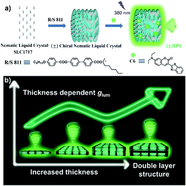
In this work, a kind of N*LC is prepared by using commercially available liquid crystal medium SLC1717, chiral dopant R/S-811, and C6 as the emitter (Fig. 1a). After locating the emission at the center of PBGs, the thickness-dependent CPL properties were studied. The results indicated that the |glum| value is not positively correlated with the increase of cell thickness. This should be attributed to the irregular arrangement of N*LC when the liquid crystal cell is too thick. Additionally, a double-layer cell structure is used to load N*LC, whose glum can be amplified to as high as 1.53 (Fig. 1b). More importantly, based on the N*LC with high-quality CPL activity, low-cost photo-resistance is able to recognize the CPL by the circular polarizer and further transfer the inputted signal to the current signal. Then, the application of a functional signal generator encrypted by CPL is successfully demonstrated.
 | ||
| Fig. 1 A scheme of (a) the preparation method of N*LC with CPL activity and (b) the non-positive correlation between thickness and glum in N*LC, the double-layer structure showing the highest glum. | ||
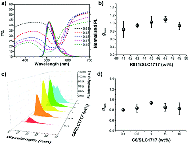
First of all, to obtain the best CPL property, the optimum ratio of the component species in N*LC is investigated. Theoretically, increasing the ratio of the chiral component concentration tends to induce the blueshift of PBGs of N*LC.36,37 As shown in Fig. 2a, tunable PBGs are given by changing the weight ratios of the chiral dopant R811/SLC1717 from 41 wt%, 43 wt%, 45 wt%, 47 wt% to 49 wt%. After adding 1 wt% C6 into N*LC with the corresponding ratio of R811/SLC1717, the emission and PBGs location only show slight changes (Fig. 2a and Fig. S1, ESI†). The tendency of the glum at different weight ratios of R811/SLC1717 is shown in Fig. 2b. The positive glum of CPL is decided by the chirality of the chiral dopant. Here, C6 in 47 wt% R811/SLC1717 presents the highest glum, which is ascribed to the maximum reflection of the PBGs center to the emission. In this case, we compare the emission of N*LC with different concentrations of C6 including 0.1 wt%, 0.5 wt%, 1 wt%, 5 wt% to 10 wt% for C6/SLC1717 (Fig. 2c). On the one hand, due to the increase of C6 concentration, the role of luminescence self-absorption leads to a redshift of emission and the highest emission intensity at 514 nm for C6/SLC1717 being equal to 1 wt%. In addition, when C6/SLC1717 reaches 10 wt%, an aggregation-caused quenching phenomenon and aggregation emission peak around 550 nm are obviously observed. Yet the location of PBGs is almost invariable for various C6 concentrations (Fig. S2, ESI†). It indicates that it is crosstalk-free to regulate emission and PBGs via the concentration of dye and chiral dopant. Since this kind of shift of emission caused by C6 concentration results in the mismatch to the center of PBGs, the glum in N*LC of 1 wt% C6 reaches a high point (Fig. 2d). It is regarded as the ideal ratio for luminescent N*LC. Then, we have analyzed the effect of the different dopants on the liquid crystal by X-ray diffraction (XRD), in which the liquid crystal always maintains a broad peak without shifting (Fig. S3, ESI†). It can be explained by the fact that the dopants are homogeneously dispersed in liquid crystals and fail to cause a liquid crystal structure variation.
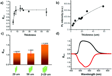
To further gain insight into factors affecting CPL, we study the chiroptical property of N*LC for various thicknesses. Based on available knowledge, as the slab thickness increases, the CPL dissymmetry factor |glum| of identical N*LC caused by selective reflection should gradually approach the ultimate value of 2 inside the stopband.35,36 Subsequently, we have further investigated the maximum glum of N*LC at the optimal ratio with different thicknesses including 3.2, 5.0, 7.7, 15.0, 18.0, 20.0, 29.0 and 58.0 μm (Fig. 3a). Interestingly, the glum is able to be enhanced by the thickness only in a relatively small range. Nevertheless, as the slab continues to thicken, the glum changes slightly. We attribute this non-positive correlation to the irregular orientation of N*LC in the thick cell. To prove this point, we give a fluorescence and transmittance spectrum analysis to different thicknesses of N*LC. The Lambert–Beer law at low concentrations for photoluminescence intensity at 524 nm with the highest glum is not suitable in the tested thickness range (Fig. 3b and Fig. S4, ESI†). The decreasing slope instead of a linear relationship supports the probable light scattering induced by the disorder of N*LC in large spaces, thus reducing the selective reflection ability of N*LC to circularly polarized light. According to the transmittance, the PBGs location will not be shifted with cell thickness variation (Fig. S4, ESI†). Furthermore, the changeable planar texture images of N*LC with various thicknesses can be observed by the polarizing optical microscope (Fig. S5, ESI†).
N*LC, which varies in depth, may change the reflection depth and direction.38–40 To avoid this issue caused by thickness, we try to use the double-layer liquid crystal cell. Two quartz glass cells with 29 μm spacers adhered to both sides are stacked to form one double-layered cell. As compared to the used cells with the same 58 μm thickness of N*LC, the glum of N*LC in the double-layered cell is dramatically amplified from 1.07 to 1.52 (Fig. 3c). In other words, the ability of selective reflection per unit thickness in the double-layered cell is stronger than the normal 58 μm N*LC, which is in accordance with this hypothesis above. However, further splitting the N*LC into three layers will result in an illumination intensity drastic decrease (Fig. S6, ESI†). Thus, it reminds us to choose suitable conditions to ensure that both the light intensity and glum are sufficient as required. Moreover, the glum curves of N*LC in the double-layered liquid crystal cell are illustrated in Fig. 3d, where S811 doped N*LC can generate a negative CPL with approximately the same magnitude of glum as using R811.
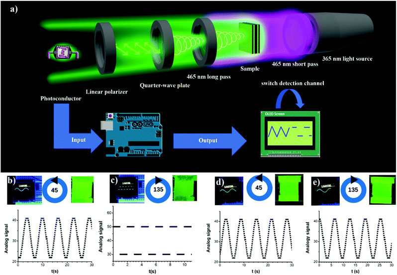
The advanced CPL properties and stability of the obtained N*LC inspire us to explore its application in information transmission (Fig. S7, ESI†). Here, we have built a brief system of the encrypted functional signal generator (Fig. S8, ESI†). As depicted in Fig. 4a, when N*LC in the double-layered cell is excited by 365 nm ultraviolet (UV) light, quality CPL is obtained. In terms of the different light intensity of CPL through different circular polarizers, two detection modes can be built to input diverse information. After switching the light intensity signal to an electrical signal via a low-cost photoconductor, we use commercial and cheap Arduino UNO as the processing unit to modulate the functional signal observed by an OLED screen.
The two kinds of polarizers for detection are composed by switching the fast axis of the quarter-wave plate to the transmission axis of the linear polarizer between 45° and 135°. When the quarter-wave plate and the linear polarizer at 45° are used as the detection channel, a high inputted light intensity signal from CPL of R-N*LC is defined to generate a sinusoidal signal (Fig. 4b). Then turning the angle between the two axes to 135° as the encryption detection mode witnesses a low light intensity responsible for the definition of square signal, as shown in Fig. 4c (also see Movie S1, ESI†). In contrast, if the prepared achiral liquid crystal C6 doped SLC1717 is used as the sample, both modes for polarization detection show the sine wave (Fig. 4d and e). Thus, there is no threshold value or light intensity difference for the identification of the two detection modes in this system. By analyzing the luminescence per layer of the liquid crystal, in addition to be the silent CPL, the achiral liquid crystal shows a relative red shift emission to N*LC with identical parameters (Fig. S9 and S10, ESI†). This should be attributed to the absence of PBGs so that the high-intensity signal is stable as input. Meanwhile, lifetime measurements have proven that a chiral dopant does not influence the radiative transition of C6 in the liquid crystal (Fig. S11, ESI†). Therefore, an encrypted square wave signal will not be displayed and the sinusoidal signal here is defined as the general read mode.
Conclusions
In conclusion, we have fabricated C6 doped N*LC with excellent CPL performance. Further study shed light on the thickness-dependent N*LC property. The dissymmetry factor |glum| will not infinitely increase to 2 inside the PBGs by thickening the cell, which is the result of the disorder assembly of the liquid crystal in a large space. Instead, glum tends to stop increasing when the cell becomes thick enough. Significantly, using a double-layer cell to load N*LC can deal with this problem. An amplified |glum| value over 1.5 was obtained, which is much higher than the N*LC in an ordinary cell with identical thickness. Furthermore, we have demonstrated a simple method to fabricate an encrypted signal generation device based on the generated excellent CPL of N*LC as the input signal. Consideration of rich readable information contained in CPL and exploring novel chiroptical materials will provide important insights into the practical applications in the field of data storage and transmission.Conflicts of interest
The authors declare no conflict of interest.Acknowledgements
This work was supported by the Ministry of Science and Technology of the People's Republic of China (2016YFA0203400); the National Natural Science Foundation of China (91856115) and the Strategic Priority Research Program of Chinese Academy of Sciences (No. XDB36000000).Notes and references
- M. Li, S.-H. Li, D. Zhang, M. Cai, L. Duan, M.-K. Fung and C.-F. Chen, Angew. Chem., Int. Ed., 2018, 57, 2889–2893 CrossRef CAS PubMed.
- Z.-P. Yan, X.-F. Luo, W.-Q. Liu, Z.-G. Wu, X. Liang, K. Liao, Y. Wang, Y.-X. Zheng, L. Zhou, J.-L. Zuo, Y. Pan and H. Zhang, Chem. – Eur. J., 2019, 25, 5672–5676 CrossRef CAS PubMed.
- Z. Han, X. Zhao, P. Peng, S. Li, C. Zhang, M. Cao, K. Li, Z.-Y. Wang and S.-Q. Zang, Nano Res., 2020, 13, 3248–3252 CrossRef CAS.
- Y. Wu, L. H. You, Z.-Q. Yu, J.-H. Wang, Z. Meng, Y. Liu, X.-S. Li, K. Fu, X.-K. Ren and B. Z. Tang, ACS Mater. Lett., 2020, 2, 505–510 CrossRef CAS.
- G. Qian, X. Yang, X. Wang, J. D. Herod, D. W. Bruce, S. Wang, W. Zhu, P. Duan and Y. Wang, Adv. Opt. Mater., 2020, 8, 2000775 CrossRef CAS.
- J. Cheng, F. Ge, Y. Xiang, H. Zhang, Y. Kuai, P. Hou, D. Zhang, L. Qiu, Q. Zhang and G. Zou, J. Mater. Chem. C, 2020, 8, 6521–6527 RSC.
- J. Tao, C. Zou, H. Jiang, M. Li, D. Lu, S. Mann and Y. Xu, CCS Chem., 2020, 0, 932–945 Search PubMed.
- H. Zheng, W. Li, W. Li, X. Wang, Z. Tang, S. X.-A. Zhang and Y. Xu, Adv. Mater., 2018, 30, 1705948 CrossRef PubMed.
- D. Zhao, H. He, X. Gu, L. Guo, K. S. Wong, J. W. Y. Lam and B. Z. Tang, Adv. Opt. Mater., 2016, 4, 534–539 CrossRef CAS.
- Y. Imai, Y. Nakano, T. Kawai and J. Yuasa, Angew. Chem., Int. Ed., 2018, 57, 8973–8978 CrossRef CAS PubMed.
- W. Li, M. Xu, C. Ma, Y. Liu, J. Zhou, Z. Chen, Y. Wang, H. Yu, J. Li and S. Liu, ACS Appl. Mater. Interfaces, 2019, 11, 23512–23519 CrossRef CAS PubMed.
- J. P. Riehl and F. S. Richardson, Chem. Rev., 1986, 86, 1–16 CrossRef CAS.
- B. X. Han, Acta Phys.-Chim. Sin., 2019, 35, 1177–1178 Search PubMed.
- J. Han, P. Duan, X. Li and M. Liu, J. Am. Chem. Soc., 2017, 139, 9783–9786 CrossRef CAS PubMed.
- J. Han, D. Yang, X. Jin, Y. Jiang, M. Liu and P. Duan, Angew. Chem., Int. Ed., 2019, 58, 7013–7019 CrossRef CAS PubMed.
- T. Zhao, J. Han, X. Jin, M. Zhou, Y. Liu, P. Duan and M. Liu, Research, 2020, 2020, 6452123 CAS.
- Y. Chen, Z. Xu, W. Hu, X. Li, Y. Cheng and Y. Quan, Macromol. Rapid Commun., 2021, 42, 2000548 CrossRef CAS PubMed.
- Y. Li, K. Liu, X. Li, Y. Quan and Y. Cheng, Chem. Commun., 2020, 56, 1117–1120 RSC.
- K. Liu, Y. Shen, X. Li, Y. Zhang, Y. Quan and Y. Cheng, Chem. Commun., 2020, 56, 12829–12832 RSC.
- B. A. San Jose, J. Yan and K. Akagi, Angew. Chem., Int. Ed., 2014, 53, 10641–10644 CrossRef CAS PubMed.
- X. Yang, J. Han, Y. Wang and P. Duan, Chem. Sci., 2019, 10, 172–178 RSC.
- Z.-W. Luo, L. Tao, C.-L. Zhong, Z.-X. Li, K. Lan, Y. Feng, P. Wang and H.-L. Xie, Macromolecules, 2020, 53, 9758–9768 CrossRef CAS.
- S. Lin, H. Sun, J. Qiao, X. Ding and J. Guo, Adv. Opt. Mater., 2020, 8, 2000107 CrossRef CAS.
- J. Li, H. K. Bisoyi, S. Lin, J. Guo and Q. Li, Angew. Chem., Int. Ed., 2019, 58, 16052–16056 CrossRef CAS PubMed.
- M. Xu, X. Wu, Y. Yang, C. Ma, W. Li, H. Yu, Z. Chen, J. Li, K. Zhang and S. Liu, ACS Nano, 2020, 14, 11130–11139 CrossRef CAS PubMed.
- X. Gao, X. Qin, X. Yang, Y. Li and P. Duan, Chem. Commun., 2019, 55, 5914–5917 RSC.
- X. Li, Y. Shen, K. Liu, Y. Quan and Y. Cheng, Mater. Chem. Front., 2020, 4, 2954–2961 RSC.
- X. Yang, M. Zhou, Y. Wang and P. Duan, Adv. Mater., 2020, 32, 2000820 CrossRef CAS PubMed.
- A. Bobrovsky, K. Mochalov, V. Oleinikov, A. Sukhanova, A. Prudnikau, M. Artemyev, V. Shibaev and I. Nabiev, Adv. Mater., 2012, 24, 6216–6222 CrossRef CAS PubMed.
- S. M. Wood, M. Prévôt, M. Amela-Cortes, S. Cordier, S. J. Elston, Y. Molard and S. M. Morris, Adv. Opt. Mater., 2015, 3, 1368–1372 CrossRef CAS.
- J. Yan, F. Ota, B. A. San Jose and K. Akagi, Adv. Funct. Mater., 2017, 27, 1604529 CrossRef.
- C.-T. Wang, K. Chen, P. Xu, F. Yeung, H.-S. Kwok and G. Li, Adv. Funct. Mater., 2019, 29, 1903155 CrossRef.
- B. M. Conger, J. C. Mastrangelo and S. H. Chen, Macromolecules, 1997, 30, 4049–4055 CrossRef CAS.
- B. M. Conger, D. Katsis, J. C. Mastrangelo and S. H. Chen, J. Phys. Chem. A, 1998, 102, 9213–9218 CrossRef CAS.
- H. Q. Shi, B. M. Conger, D. Katsis and S. H. Chen, Liq. Cryst., 1998, 24, 163–172 CrossRef CAS.
- J. Schmidtke and W. Stille, Eur. Phys. J. B, 2003, 31, 179–194 CrossRef CAS.
- X. Liu, L. Qin, Y. Zhan, M. Chen and Y. Yu, Acta Chim. Sin., 2020, 78, 478–489 CrossRef.
- W. R. Chen and J. C. Hwang, Mol. Cryst. Liq. Cryst., 2004, 423, 85–96 CrossRef CAS.
- M. E. McConney, V. P. Tondiglia, J. M. Hurtubise, L. V. Natarajan, T. J. White and T. J. Bunning, Adv. Mater., 2011, 23, 1453–1457 CrossRef CAS.
- L. J. Martínez-Miranda and Y. Hu, J. Appl. Phys., 2006, 99, 113522 CrossRef.
Footnote |
| † Electronic supplementary information (ESI) available. See DOI: 10.1039/d1ma00368b |
| This journal is © The Royal Society of Chemistry 2021 |


![[thin space (1/6-em)]](https://www.rsc.org/images/entities/char_2009.gif) :
: