
 Open Access Article
 This Open Access Article is licensed under a
 Creative Commons Attribution 3.0 Unported Licence
An environmental pollutant to an efficient solar vapor generator: an eco-friendly method for freshwater production†
Tawseef Ahmad
Wani
,
Parul
Garg
and
Ashok
Bera
 *
*
Department of Physics, Indian Institute of Technology Jammu, Jammu and Kashmir, 181221, India. E-mail: ashok.bera@iitjammu.ac.in
First published on 10th May 2021
Abstract
The solar-driven water evaporation technique to produce clean water has shown enormous potential as an energy-efficient solution for global freshwater scarcity. Designing a cost-effective and efficient solar vapor generator (SVG) using an underutilized natural source that causes environmental pollution will be an eco-friendly method for freshwater generation. We developed an SVG by simply carbonizing the surface of a piece of coconut husk using a household liquefied petroleum gas stove. The naturally porous structure of coconut husk enhances light absorption, and the 3D assembly promotes heat energy harvesting from the environment, leading to an effective energy input of 1.6 kW m−2 under 1 sun illumination (1.0 kW m−2). Our carbonized coconut husk evaporator shows an evaporation rate of 3.6 kg m−2 h−1. Due to simple design techniques, negligible material cost, and large-scale availability combined with the already existing coconut coir industries, carbonized coconut husk-based SVGs can provide an affordable method for freshwater generation.
Freshwater scarcity is now a global concern due to the increase in water pollution and the human population.1–4 Finding a cost-effective solution for freshwater generation using renewable energy sources can ultimately counter global freshwater scarcity.5 Recently, solar-driven water purification technology has been considered an energy-efficient way of producing clean water.6–12 The principle of this technology is to convert solar energy into heat that generates vapor/steam, and the main focus is to prepare efficient solar vapor generators (SVGs) using unconcentrated solar light.13,14 It has been found that heating a small amount of water near the evaporator surface while restricting the heat flow to the rest of the water improves the evaporation efficiency significantly, known as interfacial vapor generators.14–18 Such interfacial vapor generators have been used in both 2D and 3D configurations. In general, 2D SVGs consist of an absorber layer on a hydrophilic porous substrate, followed by a heat-insulating layer and an arrangement of controlled water flow to the absorber layer using capillary action.19–21 Heat loss from the absorber layer due to diffuse reflectance and radiation limits the evaporation rate of 2D SVGs, which has been addressed using 3D SVGs.22–27 Efforts have been made to fabricate highly efficient solar vapor generators by investigating different types of photothermal materials, including carbon materials,28,29 oxides,30,31 and polymers.32,33 The efficiency of evaporators has been increased by reducing the enthalpy of vaporization using hydrogel as well.34 The cost of absorber materials and the complicated design techniques of SVGs restrict the application to their full potential.
Energy shortage with increasing energy demand and the environmental crisis have forced researchers to find low-cost, eco-friendly, novel functional materials that can be commercialized shortly.35,36 Recently, the carbonization of a variety of plants and related products has been utilized to design SVGs.37–41 The unique structure of the plant stem works as a channel for conducting water in these SVGs. But the carbonization of plants requires high-temperature annealing under a controlled environment. High-temperature annealing destroys the mechanical strength and surface morphology of plants.42 Uniform deposition of the carbonized species on a substrate or self-assembling them in the desired form creates difficulties in the large-scale design of SVGs. The low efficiency of plant-based SVGs is one of the significant challenges; for example, SVGs made from mushrooms,43 lotus seeds,44 daikon,45 potato,46 rice husk,47 sugarcane,48 and banana peels49 have an evaporation rate of less than 1.5 kg m−2 h−1 under 1 sun illumination (1 kW m−2). Industry-scale availability of some of these plants might be a challenge as well. Although the evaporation rate of bamboo stem-based SVGs has been reported to be 3.1 kg m−2 h−1, it requires multistage annealing of the bamboo stem at different temperatures as high as 1200 °C.50 Finding a plant-based source material with large-scale availability, simple design techniques, and efficient SVG performance can lead to an affordable solution for freshwater generation.
Coconut (Cocos nucifera) belongs to the Arecaceae family. Almost every part of coconut plants is used in diverse applications due to their advantages like availability in large quantities, low-cost, and renewable, eco-friendly, and biodegradable nature.51,52 Among all the coconut plant products, coconut husk is reported as the most underutilized resource and it causes environmental pollution.53,54 Designing SVGs using coconut husk will further improve ecological management. Coconut husk has very low thermal conductivity and potential applications in the thermal isolation layer.55 Coconut plant-based materials are known to have high porosity which helps water conduction by capillary action. Hence, designing SVGs using coconut husk is expected to have higher efficiency. The high mechanical strength of coconut coir56 and the resiliency of coconut husk in water54 will prolong the durability of the evaporator as well.
Thus, motivated by the natural properties of coconut husk, we prepared a 3D cylindrical SVG by flaming the surface of coconut husk under environmental conditions using a liquefied petroleum gas (LPG) stove. Our carbonized coconut husk (CCH)-based evaporators show a maximum evaporation rate of 3.6 kg m−2 h−1 under 1 sun illumination (AM 1.5) and offer a thermal efficiency of 144%. Although the evaporation rate is comparable to that of other reported 3D SVGs, the easy processability combined with negligible material cost and high stability of coconut husk in water establish the superiority of CCH for practical applications. The evaporation rate remains unaffected up to a measured time of 10 hours during continuous steam generation from seawater and has the capability of self-cleaning under dark conditions. The evaporation efficiency remains unchanged for higher intensities and multiple cycles as well. The efficient evaporation capacity of CCH evaporators can be attributed to the increased surface area, effective three-dimensional structure, and the capability of heat harvesting from the environment through their larger cylindrical facet.
To prepare CCH evaporators, raw coconut husk (RCH) was cut into pieces, washed thoroughly using KOH solution, followed by DI water, compressed tightly into a cylindrical shape, and dried at 70 °C in an oven (Fig. 1). The density of coconut husk was approximately 0.33 g cm−3 after drying. Finally, its cylindrical surface and top surface were carbonized using a household LPG stove under environmental conditions. The detailed carbonization process is given in the ESI.† The cross-sectional image of the CCH (extreme right) shows that only the surface has been carbonized and the bulk remains the same, which will help in maintaining the mechanical strength of the coconut husk. As it does not require any specific tool to fabricate, an ordinary person can easily design such CCH evaporators for domestic use. The chemical composition and functional groups of RCH and CCH were determined using Fourier transform infrared (FTIR) spectroscopy, and the results are shown in Fig. 2a. The peaks for the RCH at 3258 cm−1 (O–H stretching vibration) and 1027 cm−1 (O–H bending vibration) are absent for the CCH, which confirms the degradation of the oxygen-containing groups coming from the hydroxyl groups.57 The diminished peak at 2897 cm−1 indicates the formation of unsaturated carbon–carbon bonds, which is one of the reasons for the enhanced light absorption.57 XPS analysis was performed to determine the type of chemical bonding present between the elements in CCH. An increase in the carbon concentration was estimated by the carbon-to-oxygen (C/O) ratio from the XPS spectra given in Fig. 2b. The element contents of C and O in the raw coconut husk were measured to be 73.27% and 21.11%, and in the carbonized coconut husk the contents of C and O were 82.27% and 14.71%, respectively, showing that the C/O ratio increased from 3.47 to 5.59 after carbonization. Furthermore, the fitted high-resolution C1s spectra of the raw coconut husk (Fig. S1a, ESI†) and carbonized coconut husk (Fig. 2c) show three standard peaks of C–C, C–O–C, and O–C![[double bond, length as m-dash]](https://www.rsc.org/images/entities/char_e001.gif) O located around the binding energies of 284.8 eV, 286 eV, and 288.7 eV, and the deconvoluted O1s spectra of the raw coconut husk (Fig. S1b, ESI†) and carbonized coconut husk (Fig. 2d) consist of two distinct peaks of CO and C–O at the binding energies of 533 eV and 531.5 eV, respectively. The formation of bonds between carbon and oxygen in the O1s and C1s spectra suggested the hydrophilic nature of the CCH.58 Furthermore, the immediate absorption of water droplets, when added on top, confirms the hydrophilicity of both RCH and CCH (shown in Video S1, ESI†).
O located around the binding energies of 284.8 eV, 286 eV, and 288.7 eV, and the deconvoluted O1s spectra of the raw coconut husk (Fig. S1b, ESI†) and carbonized coconut husk (Fig. 2d) consist of two distinct peaks of CO and C–O at the binding energies of 533 eV and 531.5 eV, respectively. The formation of bonds between carbon and oxygen in the O1s and C1s spectra suggested the hydrophilic nature of the CCH.58 Furthermore, the immediate absorption of water droplets, when added on top, confirms the hydrophilicity of both RCH and CCH (shown in Video S1, ESI†).
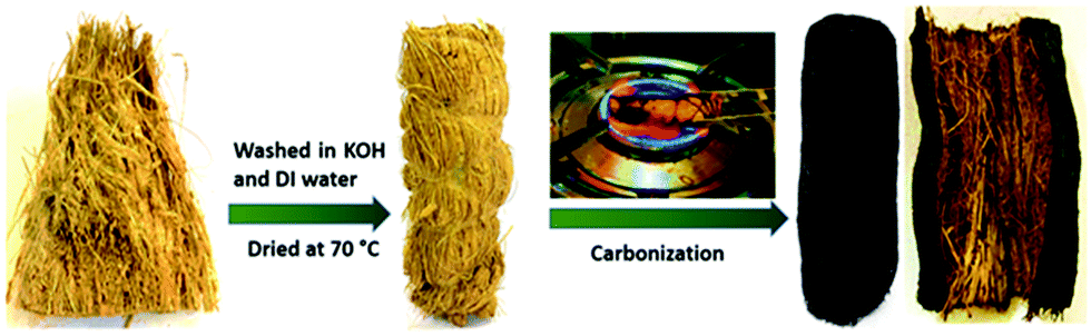 | ||
| Fig. 1 Photographs showing stepwise fabrication of a carbonized coconut husk evaporator. | ||
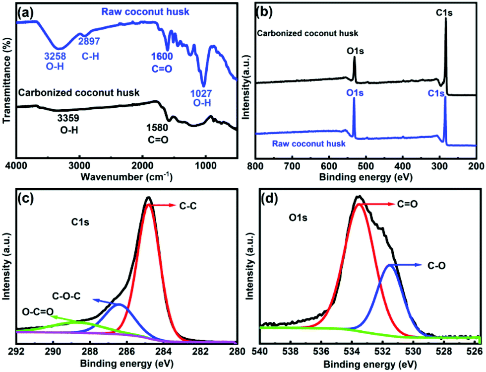 | ||
| Fig. 2 (a) FTIR spectra of coconut husk before (blue) and after (black) carbonization. (b) XPS survey spectra of the carbonized coconut husk (black) and raw coconut husk (blue). High-resolution XPS spectra of the (c) C1s and (d) O1s orbitals of coconut husk after carbonization. | ||
Coconut husk consists of fibres bonded by spongy coconut pith. The same structure was maintained after carbonization, as shown in the scanning electron microscopy images in Fig. 3a and b. The encircled region in Fig. 3b displays a fibre surrounded by the coconut pith. Furthermore, the tubular fibres with long channels (Fig. 3c) help in fast water transport. The porous structure of the CCH will enhance solar absorption by trapping the incident photons, increase the effective surface area of evaporation, and act as the escape path to the vapor from the evaporator, as shown in the model in Fig. 3d. The porous nature of coconut husk was quantified by measuring the surface area before and after carbonization using the BET (Brunauer–Emmett–Teller) method (Fig. S2, ESI†), and the estimated surface areas of RCH and CCH were 87.54 and 41.084 m2 g−1, respectively. The reduced surface area of CCH may be due to the shrinkage of coconut husk after carbonization.43,50
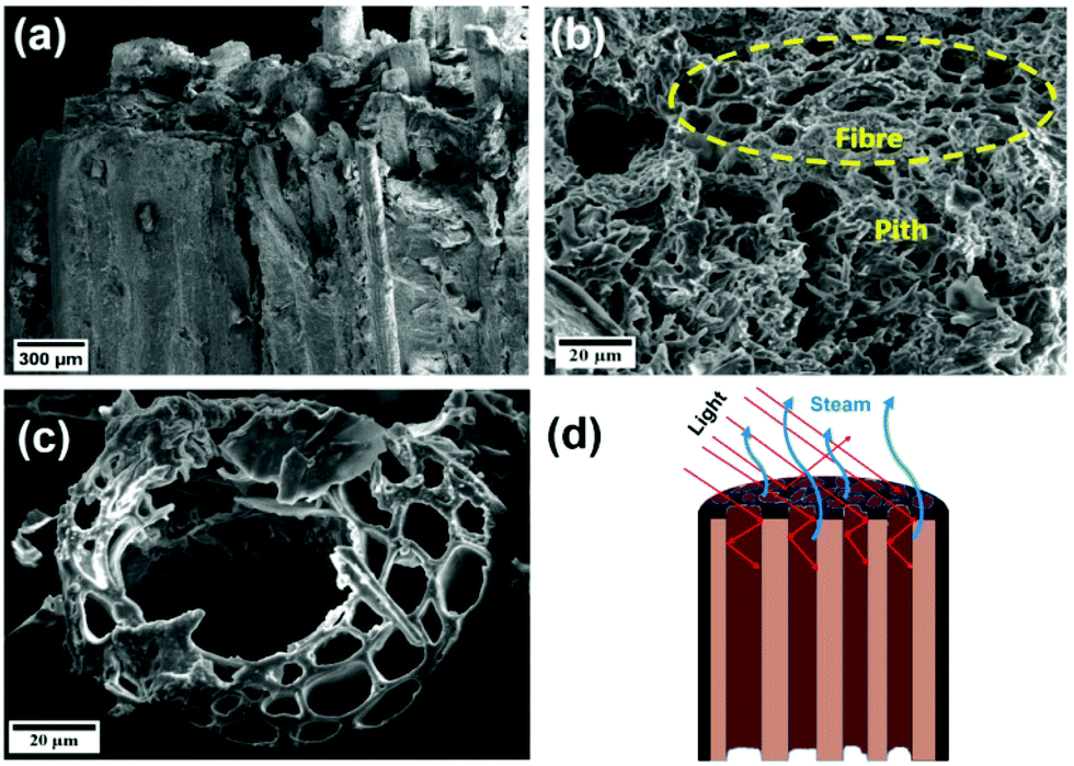 | ||
| Fig. 3 SEM images of the carbonized coconut husk evaporator: (a) side view and (b) top view. (c) SEM image of the top of a single fibre. (d) Schematic diagram showing the advantage of coconut coir in light absorption and steam escape. | ||
The diffuse reflectance of CCH was measured in both dry and wet states in the wavelength range of 300–2500 nm (Fig. 4a) to estimate the light-absorbing capability within the entire solar spectrum. Since the transmittance is zero, the CCH exhibits an average absorption of about 96% and 97.5% (Note S1, ESI†) in dry and wet states, respectively, indicating the superior light-absorbing ability of CCH after carbonization. On the contrary, 52% of the solar absorption of RCH in the dry state (Fig. S3, ESI†) shows its non-suitability for solar steam generation. The high absorption is attributed to the inherent light-absorbing property and porous nature of CCH. The heat harvesting capability of the CCH evaporator from the surrounding atmosphere was observed by the transient temperature response in the dark. Fig. 4b shows the variation of temperature on the top of the 2D CCH evaporator and its surroundings after its contact with water. The surrounding temperature away from the CCH was approximately constant, i.e. ∼23 °C (neglecting the minimal fluctuations), throughout the measurement. In contrast, the temperature of the evaporator surface slowly decreased to 19 °C after about 45 minutes, followed by saturation. The inset of Fig. 4b shows the spatial distribution of temperature after saturation. The gradual decrease in the temperature towards the evaporator is due to evaporative cooling,59 indicating the constant heat energy capture by CCH from the surrounding atmosphere to vaporize water.
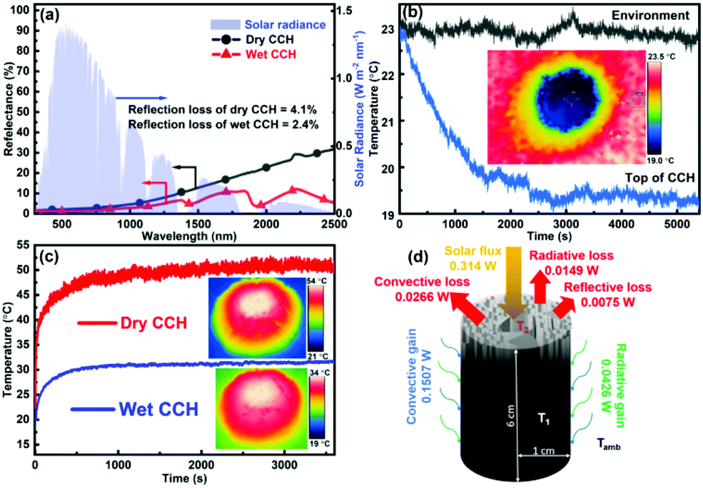 | ||
| Fig. 4 (a) Diffuse reflectance spectra of dry and wet CCH. The solar irradiation spectrum is shown in the light blue area. (b) Transient response of environmental temperature (black line) and top surface temperature (blue line) after keeping the 2D evaporator in contact with water in the dark. The thermal image in the inset shows the spatial distribution of temperature after saturation. (c) Time course of the surface temperature of dry and wet 3D CCH under 1 sun illumination and the insets show the IR thermal images of 3D CCH in dry and wet states after 1 h of illumination. (d) Schematic diagram of the coconut husk showing the heat harvesting capacity. The maximum radius of the CCH was kept at 1 cm. Total effective energy input = (solar flux + convective gain + radiative gain) = 0.5073 W for 3.13 cm2 area ≈ 1.6 kW m−2 under 1 sun illumination (1 kW m−2). | ||
Furthermore, the surface temperature of the CCH-based SVG under 1 sun illumination was recorded using an infrared camera to investigate the photothermal effect. Under 1 sun illumination, in the wet state, the average temperature increased from 19 °C to 31 °C (Fig. 4c), whereas, in the dry state, the temperature increased from 23 °C to 50 °C, suggesting efficient light-to-heat conversion. Also, under light illumination, the temperature of the middle part of the evaporator was always lower than the ambient temperature (Fig. S4, ESI†). These results confirmed the low thermal conductivity and energy harvesting capability of the CCH evaporator, which are beneficial to achieve a high evaporation rate.
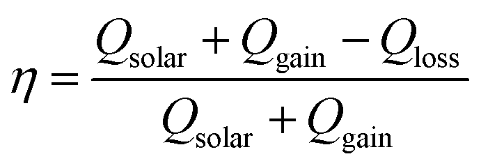
The heat exchange of the CCH evaporator with the environment at 1 sun intensity was examined using the formulae: Sεσ(T4 − Tamb4) for convective heat transfer and Sh(T4 − Tamb) for radiative heat transfer,60 where S is the area of the illuminated surface, ε is the emissivity, σ is the Stefan–Boltzmann constant, T is the average temperature (in K) of the solar absorbing surface, Tamb represents the ambient temperature (in K), and h is the convection heat transfer coefficient (10 W m−2 K−1).61 Under light illumination, the average temperature (T2) of the top surface was 31 °C compared with the value of 23 °C (Tamb) of the surrounding atmosphere; hence, the convective and radiative heat losses to the environment by CCH were 0.0266 W and 0.0149 W, respectively. The heat loss to the underlying water was neglected as the height of the CCH is too high for heat conduction. Therefore, the total energy loss to the environment, including the reflection loss (estimated from Fig. 4a), was 0.0490 W. Similarly, the convective and radiative energy gains by the cold cylindrical surface (with temperature T1) of the 3D CCH from the ambient environment were 0.1507 and 0.0426 W, respectively. Under 1 sun illumination, for a CCH-based evaporator with a radius of 1 cm and a length of 6 cm, total effective energy input = solar flux + convective gain + radiative gain = 0.5073 W ( 1.6 kW m−2), which is 1.6 times that of the solar radiation reaching the earth's surface (Fig. 4d). The energy efficiency (η) of the CCH-based SVG was calculated as 90.3% by using the following equation:61–64
Motivated by these favourable characteristics, the potential of CCH was checked for solar steam generation under ambient conditions for 2D and 3D shapes. First, the height of the CCH evaporator was optimized by measuring the evaporation rate with varying height from 0.7 cm (2D) to 7 cm under 1 sun illumination, and their performances are given in Fig. S5a (ESI†). CCH exhibits the best performance at a height of around 6 cm. This also shows the advantage of the porous nature of coconut husk that maintains controlled water flow up to a vertical height of over 6 cm with the help of capillary action. The evaporation performance of the 2D and 3D CCH evaporators with a 6 cm height under dark and 1 sun illumination conditions is plotted in Fig. 5a. Under dark conditions, evaporation rates of 0.4 kg m−2 h−1 and 1.3 kg m−2 h−1 were observed for 2D and 3D configurations, respectively, which are much faster than those of pure water (0.09 kg m−2 h−1). The impressive dark evaporation rate mainly originated from the heat harvesting capacity of the CCH evaporators, as discussed earlier. Under 1 sun illumination, the evaporation rate of the 2D evaporator was 2.2 kg m−2 h−1, and the 3D evaporator shows an average evaporation rate of 3.5 ± 0.15 kg m−2 h−1 (Fig. S5b, ESI†) with a maximum value of 3.6 kg m−2 h−1, which is comparable to those of recently reported 3D SVGs (Table S1, ESI†). The 3D evaporation rates under 2 and 3 sun illumination were 5.6 kg m−2 h−1 and 7.7 kg m−2 h−1, respectively, indicating that the evaporation rate increases linearly with intensity (Fig. S6, ESI†). At higher solar irradiance power densities, the durability of the CCH-based SVG was estimated. The 3D CCH-based evaporator shows stable performance for more than 15 cycles, each cycle of 2 h, confirming its good recycling stability (Fig. 5b). The thermal efficiency (ηth) of our CCH evaporator was calculated using the equation: ηth = ṁLVC/CoptPin,14 where ṁ is the net evaporation rate, hLV is the enthalpy of vaporization of water–vapor phase change, Copt is the optical concentration, and Pin is the solar irradiation under 1 sun illumination. The estimated ηth for the 3D CCH was 144.4% under 1 sun illumination and 90.2% when considering effective Pin as 1.6. These values are similar to the values calculated earlier using energy efficiency.
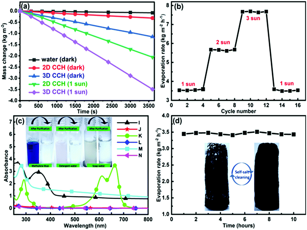 | ||
| Fig. 5 (a) Mass change of water in 2D and 3D CCH evaporators in the dark and under 1 sun illumination. (b) Evaporation rate versus cycle number at different solar power intensities. (c) UV-vis absorption spectra of polluted and purified water. I: detergent water. J: purified detergent water. K: MB solution. L: purified MB water. M: soap water. N: purified soap water. The insets show the optical images of MB, detergent and soap solution before and after purification. (d) Retention of the 3D CCH evaporator for salt water over a duration of 10 h. The insets show the optical image of the accumulated salt on the surface of the 3D CCH evaporator after 10 h under 1 sun illumination for higher salt concentrations and the self-cleaned surface under dark conditions for another 10 h. | ||
To demonstrate the practical water purification process, soap–water, detergent–water, and methylene blue (MB) solutions were selected to simulate wastewater using a handmade prototype purification setup (Fig. S7, ESI†). The absorption spectra were used to examine the concentrations of pollutants (Fig. 5c). The CCH evaporators efficiently reject the contaminants after purification, as confirmed by zero-light absorption and the color changes shown in the insets of Fig. 5c. To further evaluate the desalination effect, artificial seawater was prepared by dissolving 3.5 wt% NaCl in water. The stability of seawater purification was measured by continuously measuring the evaporation rate for 10 hours under 1 sun illumination. A nearly uniform evaporation rate in Fig. 5d shows the retention ability of the CCH evaporator without any salt accumulation on the evaporator surface. The quality of the purified water from all these solutions was further tested by measuring the pH and conductivity. The pH and conductivity values of water after purification from different contaminated solutions were found to be comparable to those of RO and DI water (Table S2, ESI†), indicating that CCH evaporators can effectively decontaminate sewage. It is worth mentioning that, during high-intensity illumination (more than 3 sun), the salt crystals start to accumulate slowly on the surface of the evaporator after 10 hours of continuous operation. As the height of the evaporator is optimized for 1 sun illumination, the lack of sufficient water flow for 3 sun illumination causes salt accumulation. However, under dark conditions, these accumulated salt crystals dissolve back into the bulk water (inset of Fig. 5d), ensuring the endurance of the CCH evaporator in seawater desalination.
Conclusions
In summary, we have demonstrated that coconut husk can be used as an efficient 3D solar vapor generator by just carbonizing its surface. 3D structures with an increased effective surface area promote energy harvesting from the environment, leading to an evaporation rate of 3.6 kg m−2 h−1 with an effective efficiency of 90.2%. In this study, the CCH evaporator shows its sustainability for seawater desalination and sewage purification. Owing to its large-scale availability and negligible material cost, combined with simple design techniques, coconut husk-based solar vapor generators may be attractive alternatives to conventional freshwater generators. Further optimization may be needed for freshwater collection after steaming for industrial-scale applications. According to recent reports, countries like Indonesia, the Philippines, India, Sri Lanka, and Mexico have increased stress of freshwater.65,66 Also, the density of coconut farming is very high in these parts of the world.67 Hence, designing efficient SVGs using coconut husk can give an immediate eco-friendly solution in these coastal parts of the world.Conflicts of interest
The authors declare no competing financial interest.Acknowledgements
We acknowledge the support of the Department of Science and Technology, Government of India via Project DST/INSPIRE/04/2016/000269.References
- J. Liu, H. Yang, S. N. Gosling, M. Kummu, M. Flörke, S. Pfister, N. Hanasaki, Y. Wada, X. Zhang, C. Zheng, J. Alcamo and T. Oki, Earths Future, 2017, 5, 545–559 CrossRef PubMed.
- T. Oki and S. Kanae, Science, 2006, 313, 1068–1072 CrossRef CAS PubMed.
- J. Eliasson, Nature, 2015, 517, 6 CrossRef CAS.
- P. Chowdhary, R. N. Bharagava, S. Mishra and N. Khan, in Environmental Concerns and Sustainable Development: Volume 1: Air, Water and Energy Resources, ed. V. Shukla and N. Kumar, Springer Singapore, Singapore, 2020, pp. 235–256 Search PubMed.
- M. A. Shannon, P. W. Bohn, M. Elimelech, J. G. Georgiadis, B. J. Mariñas and A. M. Mayes, Nature, 2008, 452, 301–310 CrossRef CAS.
- J. Yang, Y. Pang, W. Huang, S. K. Shaw, J. Schiffbauer, M. A. Pillers, X. Mu, S. Luo, T. Zhang, Y. Huang, G. Li, S. Ptasinska, M. Lieberman and T. Luo, ACS Nano, 2017, 11, 5510–5518 CrossRef CAS PubMed.
- Z. Wang, M. Han, F. He, S. Peng, S. B. Darling and Y. Li, Nano Energy, 2020, 74, 104886 CrossRef CAS.
- X. Zhao, X. J. Zha, J. H. Pu, L. Bai, R. Y. Bao, Z. Y. Liu, M. B. Yang and W. Yang, J. Mater. Chem. A, 2019, 7, 10446–10455 RSC.
- M. Gao, L. Zhu, C. K. Peh and G. W. Ho, Energy Environ. Sci., 2019, 12, 841–864 RSC.
- L. Zhu, M. Gao, C. K. N. Peh, X. Wang and G. W. Ho, Adv. Energy Mater., 2018, 8, 1702149 CrossRef.
- V. D. Dao, N. H. Vu and S. Yun, Nano Energy, 2020, 68, 104324 CrossRef CAS.
- S. Cao, Q. Jiang, X. Wu, D. Ghim, H. Gholami Derami, P. I. Chou, Y. S. Jun and S. Singamaneni, J. Mater. Chem. A, 2019, 7, 24092–24123 RSC.
- J. L. Miller, Phys. Today, 2016, 69, 17–19 CAS.
- H. Ghasemi, G. Ni, A. M. Marconnet, J. Loomis, S. Yerci, N. Miljkovic and G. Chen, Nat. Commun., 2014, 5, 1–7 Search PubMed.
- Z. Wang, Y. Liu, P. Tao, Q. Shen, N. Yi, F. Zhang, Q. Liu, C. Song, D. Zhang, W. Shang and T. Deng, Small, 2014, 10, 3234–3239 CrossRef CAS PubMed.
- Y. Xia, Q. Hou, H. Jubaer, Y. Li, Y. Kang, S. Yuan, H. Liu, M. W. Woo, L. Zhang, L. Gao, H. Wang and X. Zhang, Energy Environ. Sci., 2019, 12, 1840–1847 RSC.
- D. P. Storer, J. L. Phelps, X. Wu, G. Owens, N. I. Khan and H. Xu, ACS Appl. Mater. Interfaces, 2020, 12, 15279–15287 CrossRef CAS PubMed.
- Y. Liu, J. Chen, D. Guo, M. Cao and L. Jiang, ACS Appl. Mater. Interfaces, 2015, 7, 13645–13652 CrossRef CAS PubMed.
- Y. Lin, H. Xu, X. Shan, Y. Di, A. Zhao, Y. Hu and Z. Gan, J. Mater. Chem. A, 2019, 7, 19203–19227 RSC.
- L. Zhu, M. Gao, C. K. N. Peh and G. W. Ho, Nano Energy, 2019, 57, 507–518 CrossRef CAS.
- C. Chen, Y. Kuang and L. Hu, Joule, 2019, 3, 683–718 CrossRef CAS.
- D. Ghim, Q. Jiang, S. S. Cao, S. Singamaneni and Y. S. Jun, Nano Energy, 2018, 53, 949–957 CrossRef CAS.
- L. Wu, Z. Dong, Z. Cai, T. Ganapathy, N. X. Fang, C. Li, C. Yu, Y. Zhang and Y. Song, Nat. Commun., 2020, 11, 1–12 Search PubMed.
- P. Sun, W. Zhang, I. Zada, Y. Zhang, J. Gu, Q. Liu, H. Su, D. Pantelić, B. Jelenković and D. Zhang, ACS Appl. Mater. Interfaces, 2020, 12, 2171–2179 CrossRef CAS PubMed.
- B. Shao, Y. Wang, X. Wu, Y. Lu, X. Yang, G. Y. Chen, G. Owens and H. Xu, J. Mater. Chem. A, 2020, 8, 11665–11673 RSC.
- S. Chen, Z. Sun, W. Xiang, C. Shen, Z. Wang, X. Jia, J. Sun and C. J. Liu, Nano Energy, 2020, 76, 104998 CrossRef CAS.
- C. Tu, W. Cai, X. Chen, X. Ouyang, H. Zhang and Z. Zhang, Small, 2019, 15, 1–8 CrossRef PubMed.
- H. Ren, M. Tang, B. Guan, K. Wang, J. Yang, F. Wang, M. Wang, J. Shan, Z. Chen, D. Wei, H. Peng and Z. Liu, Adv. Mater., 2017, 29, 1702590 CrossRef PubMed.
- X. Wu, T. Gao, C. Han, J. Xu, G. Owens and H. Xu, Sci. Bull., 2019, 64, 1625–1633 CrossRef CAS.
- J. Wang, Y. Li, L. Deng, N. Wei, Y. Weng, S. Dong, D. Qi, J. Qiu, X. Chen and T. Wu, Adv. Mater., 2016, 29, 1603730 CrossRef PubMed.
- Y. Shi, R. Li, Y. Jin, S. Zhuo, L. Shi, J. Chang, S. Hong, K. C. Ng and P. Wang, Joule, 2018, 2, 1171–1186 CrossRef CAS.
- Y. Li, T. Gao, Z. Yang, C. Chen, W. Luo, J. Song, E. Hitz, C. Jia, Y. Zhou, B. Liu, B. Yang and L. Hu, Adv. Mater., 2017, 29, 1–8 Search PubMed.
- L. Zhang, B. Tang, J. Wu, R. Li and P. Wang, Adv. Mater., 2015, 27, 4889–4894 CrossRef CAS PubMed.
- F. Zhao, X. Zhou, Y. Shi, X. Qian, M. Alexander, X. Zhao, S. Mendez, R. Yang, L. Qu and G. Yu, Nat. Nanotechnol., 2018, 13, 489–495 CrossRef CAS PubMed.
- R. Fillet, V. Nicolas, V. Fierro and A. Celzard, Sol. Energy Mater. Sol. Cells, 2021, 219, 110814 CrossRef CAS.
- F. Zhao, Y. Guo, X. Zhou, W. Shi and G. Yu, Nat. Rev. Mater., 2020, 5, 388–401 CrossRef.
- C. Zhang, P. Xiao, F. Ni, L. Yan, Q. Liu, D. Zhang, J. Gu, W. Wang and T. Chen, ACS Sustainable Chem. Eng., 2020, 8, 5328–5337 CrossRef CAS.
- G. Xue, K. Liu, Q. Chen, P. Yang, J. Li, T. Ding, J. Duan, B. Qi and J. Zhou, ACS Appl. Mater. Interfaces, 2017, 9, 15052–15057 CrossRef CAS PubMed.
- L. Yang, G. Chen, N. Zhang, Y. Xu and X. Xu, ACS Sustainable Chem. Eng., 2019, 7, 19311–19320 CrossRef CAS.
- J. Li, X. Zhou, P. Mu, F. Wang, H. Sun, Z. Zhu, J. Zhang, W. Li and A. Li, ACS Appl. Mater. Interfaces, 2020, 12, 798–806 CrossRef CAS PubMed.
- Y. Long, S. Huang, H. Yi, J. Chen, J. Wu, Q. Liao, H. Liang, H. Cui, S. Ruan and Y. J. Zeng, J. Mater. Chem. A, 2019, 7, 26911–26916 RSC.
- X. Shan, A. Zhao, Y. Lin, Y. Hu, Y. Di, C. Liu and Z. Gan, Adv. Sustainable Syst., 2020, 4, 1–8 Search PubMed.
- N. Xu, X. Hu, W. Xu, X. Li, L. Zhou, S. Zhu and J. Zhu, Adv. Mater., 2017, 29, 1606762 CrossRef PubMed.
- J. Fang, J. Liu, J. Gu, Q. Liu, W. Zhang, H. Su and D. Zhang, Chem. Mater., 2018, 30, 6217–6221 CrossRef CAS.
- M. Zhu, J. Yu, C. Ma, C. Zhang, D. Wu and H. Zhu, Sol. Energy Mater. Sol. Cells, 2019, 191, 83–90 CrossRef CAS.
- C. Wang, J. Wang, Z. Li, K. Xu, T. Lei and W. Wang, J. Mater. Chem. A, 2020, 8, 9528–9535 RSC.
- W. Fang, L. Zhao, X. He, H. Chen, W. Li, X. Zeng, X. Chen, Y. Shen and W. Zhang, Renewable Energy, 2020, 151, 1067–1075 CrossRef CAS.
- J. Liu, Q. Liu, D. Ma, Y. Yuan, J. Yao, W. Zhang, H. Su, Y. Su, J. Gu and D. Zhang, J. Mater. Chem. A, 2019, 7, 9034–9039 RSC.
- J. Li, M. Du, G. Lv, L. Zhou, X. Li, L. Bertoluzzi, C. Liu, S. Zhu and J. Zhu, Adv. Mater., 2018, 30, 1805159 CrossRef PubMed.
- Y. Bian, Q. Du, K. Tang, Y. Shen, L. Hao, D. Zhou, X. Wang, Z. Xu, H. Zhang, L. Zhao, S. Zhu, J. Ye, H. Lu, Y. Yang, R. Zhang, Y. Zheng and S. Gu, Adv. Mater. Technol., 2019, 4, 1800593 CrossRef.
- E. Taer, R. Taslim, A. W. Putri, A. Apriwandi and A. Agustino, Int. J. Electrochem. Sci., 2018, 13, 12072–12084 CrossRef CAS.
- A. Divyashree, S. A. B. A. Manaf, S. Yallappa, K. Chaitra, N. Kathyayini and G. Hegde, J. Energy Chem., 2016, 25, 880–887 CrossRef.
- O. O. Olatunde, S. Benjakul and K. Vongkamjan, Int. J. Food Sci. Technol., 2019, 54, 810–822 CrossRef CAS.
- R. C. Rodrigues and A. P. O. Carvalho, Acta Acust. Acust., 2003, 89, 1–6 Search PubMed.
- S. Panyakaew and S. Fotios, Energy Build., 2011, 43, 1732–1739 CrossRef.
- R. D. T. Filho, K. Scrivener, G. L. England and K. Ghavami, Cem. Concr. Compos., 2000, 22, 127–143 CrossRef.
- Y. Kuang, C. Chen, S. He, E. M. Hitz, Y. Wang, W. Gan, R. Mi and L. Hu, Adv. Mater., 2019, 31, 1900498 CrossRef PubMed.
- W. Feng, P. He, S. Ding, G. Zhang, M. He, F. Dong, J. Wen, L. Du and M. Liu, RSC Adv., 2016, 6, 5949–5956 RSC.
- X. Li, J. Li, J. Lu, N. Xu, C. Chen, X. Min, B. Zhu, H. Li, L. Zhou, S. Zhu, T. Zhang and J. Zhu, Joule, 2018, 2, 1331–1338 CrossRef CAS.
- Y. Wang, X. Wu, X. Yang, G. Owens and H. Xu, Nano Energy, 2020, 78, 105269 CrossRef CAS.
- H. Wang, C. Zhang, Z. Zhang, B. Zhou, J. Shen and A. Du, Adv. Funct. Mater., 2020, 30, 1–10 Search PubMed.
- W. Huang, G. Hu, C. Tian, X. Wang, J. Tu, Y. Cao and K. Zhang, Sustainable Energy Fuels, 2019, 3, 3000–3008 RSC.
- Y. S. Jun, X. Wu, D. Ghim, Q. Jiang, S. Cao and S. Singamaneni, Acc. Chem. Res., 2019, 52, 1215–1225 CAS.
- L. Zhang, B. Bai, N. Hu and H. Wang, Appl. Therm. Eng., 2020, 171, 115059 CrossRef CAS.
- M. M. Mekonnen and A. Y. Hoekstra, Sci. Adv., 2016, 2, 1–7 Search PubMed.
- N. Mancosu, R. L. Snyder, G. Kyriakakis and D. Spano, Water, 2015, 7, 975–992 CrossRef.
- P. K. Ghosh, P. Bhattacharjee, S. Mitra and M. Poddar-Sarkar, Int. J. Food Sci., 2014, 2014, 310852 Search PubMed.
Footnote |
| † Electronic supplementary information (ESI) available: Experimental methods, calculation of solar absorptance, calculation of evaporation efficiency, table showing the comparison of the CCH-based SVG with other recently reported 3D SVGs, photograph of the prototype CCH evaporator, table of pH and conductivity values. See DOI: 10.1039/d1ma00361e |
| This journal is © The Royal Society of Chemistry 2021 |