A lithium-ion oxygen battery using a polyethylene glyme electrolyte mixed with an ionic liquid†
Giuseppe Antonio Eliaa,
Rebecca Bernhardb and
Jusef Hassoun*a
aDepartment of Chemistry, Sapienza University, Piazzale Aldo Moro 5, 00185 Rome, Italy. E-mail: jusef.hassoun@uniroma1.it
bDepartment of Chemistry, TU München, Lehrstuhl für Technische Elektrochemie, Lichtenbergstrasse 4, D-85748 Garching, Germany
First published on 9th February 2015
Abstract
In this paper, we propose a new electrolyte formed by dissolving lithium-bis-(trifluoromethanesulfonyl)-imide (LiTFSI) salt in a long chain glyme, i.e. poly(ethylene glycol)500-dimethylether (PEG500DME) mixed with methyl butyl pyrrolidinium-bis-(trifluoromethanesulfonyl)-imide (Pyr14TFSI) ionic liquid. The electrolyte composition ensures both very low volatility and good performance as demonstrated by thermal analysis and electrochemical tests. The selected solution is efficiently employed as the electrolyte both in a lithium–oxygen half-cell, and in a full lithium-ion oxygen battery using a Li–Sn–C nanostructured composite anode, thus suggesting the suitability of the polyethylene glyme mixed with the ionic liquid for application in high-energy storage systems.
Introduction
The recent growth of the electric vehicle market suggests that a lithium ion battery, i.e. the highest energy density system commercially available, based on a transition metal oxide cathode and graphite anode, may be insufficient to grant a satisfactory driving range. Indeed, the current state lithium-ion battery shows an energy density of 180 W h kg−1 that may lead to an authonomy approaching 150 km with a single charge,1 i.e. a value far from the one associated to the common combustion engines. Recent studies demonstrated that electrochemical systems based on the reaction of oxygen with the lithium metal, namely lithium–air or lithium–oxygen batteries, can theoretically store an energy density of 1000 W h kg−1 and significantly increase the driving range of the electric vehicle.1–5 Non–aqueous lithium–oxygen battery conventionally employs a carbon supported cathode for the oxygen electrochemical reaction, an organic liquid electrolyte and lithium metal as the anode. However, several drawbacks are still limiting the lithium–air battery performance such as the poor electrolyte stability, short cycle life and low energy efficiency due to the high charge–discharge polarization.6–9 It has been demonstrated that the electrolyte decomposition in a lithium–oxygen battery is mainly due to the reactivity of the nucleophilic O2−˙ species, i.e. superoxide radical, formed as intermediates during the electrochemical reduction of oxygen with organic solvents, in particular with the carboxyl group of the carbonate-based solutions conventionally used as electrolytes in lithium batteries.10,11 Recent studies suggested that long-chain glymes, such as tetraethylene glycol dimethyl ether, are suitable electrolyte media for lithium–air battery application, due to the stability of the ether bonds in these solvents against the nucleophilic attack of the superoxide.12–14 Additional issues affecting the lithium–air battery, which is, in principle, an open system, are the possible electrolyte volatility and excessive evaporation, inducing a resistance increase resulting in cell failure, and safety concerns associated with the use of the lithium metal anode.15 Indeed, electrolytes characterised by high viscosity, low volatility and good compatibility with lithium both in terms of ion transport and chemical stability, are the preferred solution to be used in lithium–air batteries. Recent papers demonstrated the applicability of glyme-based solutions in lithium-ion batteries,16 the stability of ionic liquids toward superoxide radicals17 and the suitability of the glyme–IL combination as the electrolyte in lithium oxygen batteries. Furthermore, a recent study proposed a silicon–carbon lithium-alloy electrode as an alternative to the lithium metal anode in a full lithium-ion oxygen cell.18 In this paper, we report a lithium-ion oxygen battery using a solution of LiTFSI salt in poly(ethylene glycol)500-dimethylether (PEG500DME) mixed with Pyr14TFSI ionic liquid as the electrolyte. Poly(ethylene glycol)500 solvent shows high thermal stability and low vapor pressure (<0.004 mm Hg at room temperature), and hence an extremely limited volatility, while Pyr14TFSI is expected to stabilize the O2−˙ species formed during the electrochemical process.17 Further improvements to the cell configuration, particularly concerning its safety, is represented by the use of a Li–Sn–C electrode as an alternative to lithium metal. Indeed, the full cell is based on the Li–O2 electrochemical process at the cathode and the Li–Sn alloying process at the anode. Our results demonstrated the favorable thermal and electrochemical properties of the new PEG500DME–Pyr14TFSI–LiTFSI electrolyte and its suitability for lithium oxygen battery both in half-cell and full-cell configurations.Experimental
The electrolyte was prepared using poly(ethylene glycol)500-dimethylether (PEG500DME; M = 500 g mol−1, Sigma Aldrich) as the solvent. Prior to use, PEG500DME was purified from BHT phenolic antioxidant (2,6-di-tert-butyl-4-methyl phenol), added by the supplier at 100 ppm, using a chromatographic column loaded with neutral, activated aluminum oxide (Neutral, Brockmann I Sigma Aldrich). PEG500DME was vacuum dried at 100 °C overnight and subsequently using dry zeolites 4 Å until the water content was below 5 ppm. The first electrolyte medium (subsequently indicated by the acronym PEG0) was prepared by dissolving 1 mol kg−1 of lithium-bis-(trifluoromethanesulfonyl)-imide (LiTFSI Sigma Aldrich, 99.95%) in PEG500DME. Before use, the salt was dried overnight under vacuum at 100 °C. Methyl butyl pyrrolidinium-bis-(trifluoromethanesulfonyl)-imide (Pyr14TFSI, Solvionic) ionic liquid was added to the PEG0 solution in 2 weight ratios, i.e. 1![[thin space (1/6-em)]](https://www.rsc.org/images/entities/char_2009.gif) :
:![[thin space (1/6-em)]](https://www.rsc.org/images/entities/char_2009.gif) 9 and 3
9 and 3![[thin space (1/6-em)]](https://www.rsc.org/images/entities/char_2009.gif) :
:![[thin space (1/6-em)]](https://www.rsc.org/images/entities/char_2009.gif) 7, and the corresponding solutions were called PEG10 and PEG30, respectively. Before use, the ionic liquid was vacuum dried at 140 °C overnight with a final water content lower than 5 ppm. The tetraethylene glycol dimethyl ether (TEG-DME 99% Sigma Aldrich) was dried before use, until the water content was below 5 ppm, employing zeolite 4 Å. The TEG-DME electrolyte, used as the reference solution in the ESI, was prepared by dissolving 1 mol kg−1 of lithium-bis-(trifluoromethanesulfonyl)-imide (LiTFSI Sigma Aldrich, 99.95%) as a conductive lithium salt.
7, and the corresponding solutions were called PEG10 and PEG30, respectively. Before use, the ionic liquid was vacuum dried at 140 °C overnight with a final water content lower than 5 ppm. The tetraethylene glycol dimethyl ether (TEG-DME 99% Sigma Aldrich) was dried before use, until the water content was below 5 ppm, employing zeolite 4 Å. The TEG-DME electrolyte, used as the reference solution in the ESI, was prepared by dissolving 1 mol kg−1 of lithium-bis-(trifluoromethanesulfonyl)-imide (LiTFSI Sigma Aldrich, 99.95%) as a conductive lithium salt.
The ionic conductivity of the electrolytes was investigated, from room temperature up to 100 °C, using a Metrohm blocking electrode system and electrochemical impedance spectroscopy within a 200 kHz to 100 Hz frequency range. The lithium transference number was evaluated using the Bruce–Vincent method,19 i.e. by applying a DC signal of 30 mV to a symmetrical lithium/lithium cell, and measuring the cell impedance before and after the chronoamperometry in a 500 kHz to 10 mHz frequency range. The stability of the lithium/electrolyte interphase under stationary conditions was investigated by measuring the variation of the impedance of a symmetrical lithium/lithium cell during the storage time. The measurement was performed in a frequency range of 500 kHz to 10 mHz. The stability of the lithium/electrolyte interphase under dynamic conditions was investigated by lithium stripping–deposition measurement, performed using a symmetrical lithium/lithium cell at a current of 0.1 mA cm−2 and a deposition–stripping time of 1 hour. The electrochemical stability window of the electrolyte has been verified using linear sweep voltammetry, employing a Swagelok three electrodes cell, using lithium metal as the counter and reference electrodes and an aluminum disk coated with Super-P as the working electrode. The above measurements were performed using a Biologic VSP Multipotentiostat. The thermal properties of the electrolytes were investigated by thermogravimetric analysis (TGA) and differential scanning calorimetry (DSC). TGA was performed within a temperature range of 25 to 500 °C under constant nitrogen flux and with a heating rate of 10 °C min−1 using a Mettler Toledo TGA/SDTA 851. The DSC measurement was performed within a temperature range of 40 to −90 °C with a cooling/heating rate of 5 °C min−1 using a Mettler Toledo DSC821e.
The lithium–oxygen half-cell was assembled by employing a meshed 2032 coin cell, a Toray Carbon Paper TGP-H-030 gas diffusion layer, coated by Super P carbon (Timcal) with a loading of the order of 0.5–0.6 mgC cm−2 as the cathode and lithium metal foil as the anode.12 The galvanostatic cycling test was performed using a current of 200 mA gC−1, and by limiting the delivered capacity to 1000 mA h gC−1 at 30 °C. The capacity and the current density were referred to the carbon weight of the cathode.
The Sn–C/oxygen lithium-ion cell was assembled using a nanostructured tin carbon composite anode synthesized as reported in previous papers18 with a mass loading of about 3 mg cm−2. The Sn–C anode was chemically lithiated before the cell assembly through direct contact with a lithium foil wetted with a EC![[thin space (1/6-em)]](https://www.rsc.org/images/entities/char_2009.gif) :
:![[thin space (1/6-em)]](https://www.rsc.org/images/entities/char_2009.gif) DMC 1 M LiPF6 (Merck battery grade LP30) solution for 8 hours, applying a pressure of 1 kg cm−2 as reported in a previous paper.20 Afterwards, the lithium foil was removed and the electrode was washed with dimethyl carbonate and vacuum-dried in order to remove residual solvent. The Li–Sn–C/oxygen cell was assembled using PEG10 as the electrolyte, employing a current of 100 mA gC−1 and limiting the delivered capacity to 500 mA h gC−1.
DMC 1 M LiPF6 (Merck battery grade LP30) solution for 8 hours, applying a pressure of 1 kg cm−2 as reported in a previous paper.20 Afterwards, the lithium foil was removed and the electrode was washed with dimethyl carbonate and vacuum-dried in order to remove residual solvent. The Li–Sn–C/oxygen cell was assembled using PEG10 as the electrolyte, employing a current of 100 mA gC−1 and limiting the delivered capacity to 500 mA h gC−1.
Results and discussion
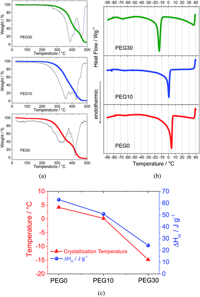
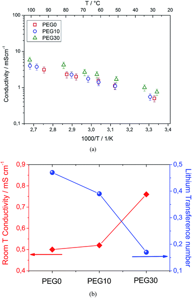
Fig. 1 reports the thermal characteristics of the three investigated electrolyte solutions. The thermogravimetric profile and the corresponding derivative trace for the PEG0 electrolyte (Fig. 1a, red curve) reveal a first weight loss at about 320 °C due to solvent evaporation and a second weight loss, at about 420 °C, ascribed to the decomposition of the TFSI anions.21 The addition of 10% and 30% ionic liquid leads to an increase in evaporation temperature to 360 and 390 °C, for PEG10 (blue curve) and PEG30 (green curve), respectively, as expected from the boiling point elevation at higher ionic species content. The increase in evaporation temperature reflects an improved thermal stability allowing the use of the electrolyte in a wide temperature range. The DSC traces of the electrolytes reported in Fig. 1b show a main endothermic transition associated to the PEG500DME crystallization and consequent electrolyte freezing. The addition of the ionic liquid to the electrolyte decreases both the freezing temperature and corresponding endothermic peak magnitude, as clearly demonstrated in Fig. 1c, reporting in summary the data obtained by the DSC analysis. The addition of 10% ionic liquid lowers the freezing point to 0 °C, while a further increase in ionic liquid content up to 30% lowers the freezing point to −14 °C. The crystallization enthalpy (ΔHm) trend, i.e. decreasing from 65 to 25 J g−1 by IL addition, may be ascribed to the reduction in the crystalline degree upon freezing due to the change of the solutions’ nature.Fig. 2a shows the Arrhenius plots of the investigated electrolytes. The bare PEG0 electrolyte shows a conductivity ranging from 1 mS cm−1 to 10 mS cm−1. It should be noted that this conductivity value is lower with respect to the value expected for the conventional TEG-DME-based electrolyte (see Fig. S1 in the ESI†). This difference may be attributed to the higher viscosity of PEG500DME with respect to TEG-DME, i.e. 15 mm2 s−1 (40 °C) and 4.1 mm2 s−1 (20 °C), respectively. Despite the lower conductivity, the PEG500DME-based electrolyte ensures suitable characteristics for application in high energy density lithium–oxygen batteries, in addition to the high thermal stability due to its lower vapor pressure with respect to TEG-DME, i.e. 0.004 mm Hg vs. 0.01 mm Hg at room temperature, respectively. Indeed, Fig. 2a evidences a minor conductivity change by the addition of 10% Pyr14TFSI to the electrolyte (PEG10, blue circles), while a remarkable increase may be obtained by further addition, up to 30% (PEG30, green triangles). The ionic conductivity increase may be reasonably attributed to a significant increase in the ionic species content (charge carriers) within the solution.
Fig. 2b summarizes the ion conduction properties of the three investigated electrolytes, in terms of conductivity at room temperature (25 °C), as determined from the Arrhenius plot in Fig. 2a, and the lithium transference number evaluated using the Bruce–Vincent method.19 The plot shows that the increase in ionic conductivity observed by increasing the ionic liquid content from 0 to 30% is accompanied by a decrease in the lithium transference number, from tLi = 0.5 in PEG0 to tLi = 0.4 in PEG10 and tLi = 0.2 in the PEG30 electrolyte. The trend of the lithium transference number is most likely due to the increased ionic strength promoted by the addition of the ionic liquid. Indeed, the increase in ion concentration results in a higher number of charge carriers that enhances the overall ionic conductivity but, on the other hand, causes the formation of ionic couples and decreases the lithium-ion transport.
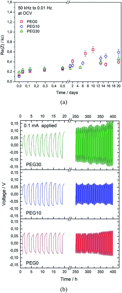
Fig. 3a shows the evolution of the overall resistance of the symmetrical lithium/lithium cell during the storage time using the three investigated electrolytes, with the aim to study the stability of the lithium/electrolyte interphase under stationary conditions. The cell using the PEG0 solution shows an initial resistance value of about 0.1 kΩ, that subsequently increases to a maximum value of 0.6 kΩ and finally decreases and stabilizes at about 0.4 kΩ, due to the formation, partial dissolution and final stabilization of a solid electrolyte interphase (SEI) film at the lithium surface.22 The cells using the PEG10 and PEG30 electrolytes show a very similar trend, thus suggesting only minor effects of ionic liquid addition on the lithium/electrolyte interphase stability. The slight differences in the resistance values between the three electrolytes, as observed in Fig. 3a, may be reasonably attributed to the different chemical natures of the SEI films formed in the presence of the ionic liquid. The electrochemical stability of the electrolytes has been further investigated by linear sweep voltammetry and is reported in Fig. S2 in the ESI†. The figure shows a stability extended up to 4.8 V vs. Li, both for the bare (PEG0) and the IL-containing (PEG10 and PEG30) electrolytes, with only minor differences. The stability of the lithium/electrolyte interphase has also been evaluated under dynamic conditions, i.e. under a current flow. Fig. 3b shows the voltage profiles of the galvanostatic lithium stripping–deposition tests performed using the three investigated electrolytes in symmetrical Li-cells. The cells using PEG0 and PEG10 show similar behaviors, characterized by a polarization below 10 mV. Instead, the cell using the PEG30 electrolyte shows increased polarization over time, remaining however at a value of a few mV. It may be reasonable to assume that the higher Li-deposition/stripping cell polarization using the PEG30 solution is mainly due to the lower lithium transference number.
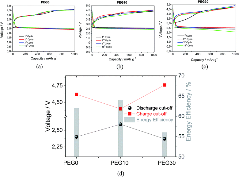
Fig. 4 shows the voltage profiles of the lithium–oxygen cells using the three investigated electrolytes. The cell using PEG0 (Fig. 4a) reveals a stable cycling behavior, extended to 15 (dis-)charge cycles, thus suggesting the stability of the electrolyte in the lithium–oxygen cell, in particular, against the reactivity of the O2−˙ species formed as intermediates during the electrochemical process. The observed stability of the PEG-based electrolyte is in agreement with previous results, obtained using similar ether-based electrolytes such as TEG-DME and polyethylene oxide (PEO),10,12,23,24 as evidenced by Fig. S3 in the ESI† reporting the galvanostatic cycling behavior of the lithium–oxygen cell employing a TEG-DME based electrolyte under the same cycling conditions. The lithium oxygen cells using the PEG10 (Fig. 4b) and PEG30 (Fig. 4c) electrolytes show satisfactory performances, as expected due to the suitability of the Pyr14TFSI ionic liquid for lithium–air battery applications.16,24–26 Fig. 4d, reporting the lithium–air cell characteristics in terms of polarization and energy efficiency using the various electrolytes, reveals optimized performances for the cell using the electrolyte with the addition of 10% in weight of the Pyr14TFSI ionic liquid. Indeed, the results suggest PEG10 as an appropriated solution in terms of a suitable ionic conductivity, high lithium transference number and remarkable stability against lithium metal, for application in lithium oxygen batteries.
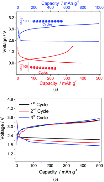
Considering the suitable electrochemical characteristics and the good behavior in the half-cell, the PEG10 electrolyte has been selected for application in a full lithium-ion oxygen cell employing a Li–Sn–C nano-composite as the anode material. Fig. 5a shows, in comparison, the voltage profiles of the lithium–oxygen (in blue) and lithium/Sn–C (in red) half cells using the PEG10 electrolyte, and the insets show the corresponding cycling responses. The lithium oxygen cell evidences discharge and charge processes centered at about 2.6 and 3.9 V vs. Li/Li+, respectively, with a capacity limited to 1000 mA h g−1, while the half-cell using the Li–Sn–C anode shows an average working voltage of about 0.4 V vs. Li/Li+ and a delivered capacity approaching 400 mA h g−1. Considering the differences in the specific capacities between the anode and cathode, the proper full cell balance has been reached using a slight excess of the Li–Sn–C anode and by limiting the capacity delivered by the cell to 500 mA h g−1. The cycling performance of the Li–Sn–C/PEG10/oxygen cell reported in Fig. 5b reveals the expected profile, with the discharge and charge processes centered at about 2.3 and 3.2 V, respectively. Furthermore, the full cell shows a lower cell overpotential, i.e. limited to 0.9 V, with respect to that expected for the combination of the corresponding half-cells reported in Fig. 5a. This positive response is most likely ascribed to the lower reactivity of the Li–Sn–C alloy anode with respect to that of the lithium metal used in the half-cell. Indeed, the Li-metal is considered to be one of the major contributors to the lithium–air cell polarization and its low energy efficiency, as already demonstrated by Edström et al.27 However, the lithium-ion cell still evidences a decrease in operating voltage during cycling, most likely due to the direct reaction of the oxygen diffused within the electrolyte with the anode side and the consequent change of the cell balance, as already evidenced in previous work.18 A possible solution to this issue may be the use of a protective film, such as LISICON or NASICON films, at the anode side avoiding the direct reaction with the dissolved oxygen and, at the same time, allowing the lithium-ion diffusion to the electrode material.28,29
Conclusion
Herein, we developed a PEG-DME-based, IL-containing electrolyte characterized by high conductivity, suitable Li-interphase and remarkable thermal stability. These characteristics, in addition to the expected stability against the nucleophilic superoxide radicals, allowed the application of the electrolyte in a lithium–oxygen battery. Furthermore, the electrolyte solution has been used in a full cell replacing the lithium metal with a lithium–tin alloy anode. The preliminary results indicated that the full cell is characterized by a high energy content and is remarkably safe. Further work on the anode-side protection in an oxygen atmosphere is still required in order to increase the full-cell cycle life. The PEG-DME-based, IL-containing electrolyte is proposed as a suitable medium for application in high-energy storage systems.References
- P. G. Bruce, S. A. Freunberger, L. J. Hardwick and J.-M. Tarascon, Nat. Mater., 2012, 11, 19 CrossRef CAS PubMed.
- F. T. Wagner, B. Lakshmanan and M. F. Mathias, J. Phys. Chem. Lett., 2010, 1, 2204–2219 CrossRef CAS.
- G. Girishkumar, B. McCloskey, A. C. Luntz, S. Swanson and W. Wilcke, J. Phys. Chem. Lett., 2010, 1, 2193–2203 CrossRef CAS.
- M. Park, H. Sun, H. Lee, J. Lee and J. Cho, Adv. Energy Mater., 2012, 2, 780–800 CrossRef CAS.
- F. Li, T. Zhang and H. Zhou, Energy Environ. Sci., 2013, 6, 1125 CAS.
- Y. Shao, F. Ding, J. Xiao, J. Zhang, W. Xu, S. Park, J.-G. Zhang, Y. Wang and J. Liu, Adv. Funct. Mater., 2013, 23, 987–1004 CrossRef CAS.
- Y.-C. Lu, B. M. Gallant, D. G. Kwabi, J. R. Harding, R. R. Mitchell, M. S. Whittingham and Y. Shao-Horn, Energy Environ. Sci., 2013, 6, 750–768 CAS.
- Z. Peng, S. A. Freunberger, Y. Chen and P. G. Bruce, Science, 2012, 337, 563 CrossRef CAS PubMed.
- T. Zhang and H. Zhou, Angew. Chem., Int. Ed., 2012, 51, 11062–11067 CrossRef CAS PubMed.
- J. Hassoun, F. Croce, M. Armand and B. Scrosati, Angew. Chem., Int. Ed., 2011, 50, 2999 CrossRef CAS PubMed.
- S. A. Freunberger, Y. Chen, Z. Peng, J. M. Griffin, L. J. Hardwick, F. Bardé, P. Novàk and P. G. Bruce, J. Am. Chem. Soc., 2011, 133, 8040 CrossRef CAS PubMed.
- H. G. Jung, J. Hassoun, J. B. Park, Y. K. Sun and B. Scrosati, Nat. Chem., 2012, 4, 579 CrossRef CAS PubMed.
- C. Ó. Laoire, S. Mukerjee, E. J. Plichta, M. A. Hendrickson and K. M. Abraham, J. Am. Chem. Soc., 2012, 158, A302 Search PubMed.
- R. Black, S. H. Oh, J.-H. Lee, T. Yim, B. Adams and L. F. Nazar, J. Am. Chem. Soc., 2012, 134, 2902 CrossRef CAS PubMed.
- J. Lu, L. Li, J. B. Park, Y. K. Sun, F. Wu and K. Amine, Chem. Rev., 2014, 114, 5611–5640 CrossRef CAS PubMed.
- R. Bernhard, A. Latini, S. Panero, B. Scrosati and J. Hassoun, J. Power Sources, 2013, 226, 329–333 CrossRef CAS PubMed.
- J. Herranz, A. Garsuch and H. A. Gasteiger, J. Phys. Chem. C, 2012, 116, 19084–19094 CAS.
- J. Hassoun, H.-G. Jung, D. J. Lee, J.-B. Park, K. Amine, Y.-K. Sun and B. Scrosati, Nano Lett., 2012, 12, 5775–5779 CrossRef CAS PubMed.
- J. Evans, C. A. Vincent and P. G. Bruce, Polymer, 1987, 28, 2324 CrossRef CAS.
- J. Hassoun, K.-S. Lee, Y.-K. Sun and B. Scrosati, J. Am. Chem. Soc., 2011, 133, 3139 CrossRef CAS PubMed.
- H. Ohno, M. Yoshizawa and W. Ogihara, Electrochim. Acta, 2003, 48, 2079 CrossRef CAS.
- D. Aurbach, J. Power Sources, 2000, 89, 206 CrossRef CAS.
- G. A. Elia, J.-B. Park, Y.-K. Sun, B. Scrosati and J. Hassoun, ChemElectroChem, 2014, 1, 47–50 CrossRef CAS.
- J.-B. Park, J. Hassoun, H.-G. Jung, H.-S. Kim, C. S. Yoon, I.-H. Oh, B. Scrosati and Y.-K. Sun, Nano Lett., 2013, 13, 2971–2975 CrossRef CAS PubMed.
- S. Monaco, F. Soavi and M. Mastragostino, J. Phys. Chem. Lett., 2013, 4, 1379–1382 CrossRef CAS.
- F. De Giorgio, F. Soavi and M. Mastragostino, Electrochem. Commun., 2011, 13, 1090–1093 CrossRef CAS PubMed.
- R. Younesi, M. Hahlin, M. Roberts and K. Edström, J. Power Sources, 2013, 225, 40–45 CrossRef CAS PubMed.
- F. Mizuno, A. Hayashi, K. Tadanaga and M. Tatsumisago, Adv. Mater., 2005, 17, 918 CrossRef CAS.
- J. Fu, US Patent no. 5,702,995, 1997.
Footnote |
| † Electronic supplementary information (ESI) available. See DOI: 10.1039/c4ra17277a |
| This journal is © The Royal Society of Chemistry 2015 |

