Making a better organic–inorganic composite electrolyte to enhance the cycle life of lithium–sulfur batteries†
Il Young Choia,
Hoon Kimb and
Moon Jeong Park*ab
aDivision of Advanced Materials Science, Pohang University of Science and Technology (POSTECH), Pohang, Korea 790 784. E-mail: moonpark@postech.edu
bDepartment of Chemistry, Pohang University of Science and Technology (POSTECH), Pohang, Korea 790 784
First published on 6th November 2014
Abstract
A new methodology for resolving the long-standing obstacles of Li–S batteries by the synthesis of a composite gel polymer electrolyte with a unique internal structure is disclosed in this paper. The Li–S cells prepared using this novel electrolyte system exhibit high discharge capacities (1140 mA h g−1 during the 1st cycle and reversible capacity of 970 mA h g−1 at the 100th cycle) and improved cycle life.
Considerable efforts have been devoted toward the development of lithium ion batteries (LIBs) for over two decades.1 In particular, much of the recent work has been devoted to exploiting high-energy density LIBs, with a focus on designing new electrode active materials suitable for various applications ranging from mobile phones to large-scale energy storage systems.2 Elemental sulfur is one of the most attractive cathode active materials for large-scale energy storage systems by taking advantages of its extraordinarily high theoretical specific capacity (1675 mA h g−1) and energy density (2567 W h kg−1).3 Furthermore, sulfur presents benefits such as non-toxicity, low price, and natural abundance.
Despite their positive aspects, lithium–sulfur (Li–S) batteries suffer from severe capacity fading during cycling, which is mainly attributed to the dissolution of lithium polysulfide intermediates into liquid electrolytes.4 It is likely that the dissolved polysulfides deposit as insoluble solid layers at the electrode surfaces during repeated charge/discharge cycles, leading to an increase in the impedance of the cell, decrease in the Coulombic efficiency, and the loss of active materials.5
In this context, many studies have been carried out to overcome the issue of polysulfide dissolution. The most significant progress has been made by employing nanostructured carbon materials as cathode frameworks, which physically encapsulate the sulfur.3,6 This approach has been proven to substantially improve the cycle life of Li–S batteries over a few hundred cycles. Of the various strategies, another promising means for inhibiting polysulfide dissolution is by designing a new electrolyte. In particular, polymer electrolytes that can serve as a physical barrier to the diffusion of dissolved polysulfide intermediates from the cathode to the anode are promising.7 Mechanical stability and ease of processing, along with flexible form factors, are some additional benefits of the polymer electrolytes. However, these electrolytes have received relatively less attention compared to the cathode materials.
The most widely studied polymer electrolytes can be categorized into solid polymer electrolytes (SPEs)8 and gel polymer electrolytes (GPEs).9 Poly(ethylene oxide) (PEO)-based polymers have long been considered to be promising candidates for SPEs.10 However, their significantly low ionic conductivity at room temperature (<10−5 S cm−1) has been a deterrent to their practical use in batteries. As an alternative for SPEs, GPEs composed of liquid electrolytes with high ionic conductivity embedded within mechanically robust polymer matrices have attracted attention.11 Nevertheless, the application of GPEs in Li–S batteries appears far-fetched, given that long-term battery performance over hundred cycles has been rarely reported. The poor long-term performance is attributed to the dissolution of lithium polysulfides into the GPEs through liquid ingredients.12
From this standpoint, the fabrication of composite gel polymer electrolytes (CPEs) by incorporating nanosized inorganic fillers into the GPEs is being explored.7a,b,13 The benefits of CPEs over the conventional GPEs in Li–S battery systems are three-fold. First, they impart improved mechanical properties without significant loss of ionic conductivity. Secondly, the shuttling of lithium polysulfide intermediates between the electrodes is suppressed, owing to the presence of physical barriers (inorganic fillers) when the polysulfides reach the liquid electrolytes. Thirdly, improved lithium salt dissociation is achieved, by incorporating high dielectric constant inorganic materials with a large surface area. Although the potential for application of the CPEs in Li–S batteries appears to be immense, the successful development of Li–S batteries containing CPEs with performance surpassing that of conventional Li–S cells based on liquid electrolytes is still in its infancy.
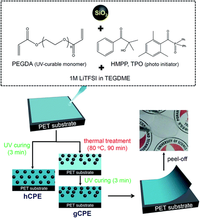
Herein, we report a new design for CPEs with the goal of increasing the energy density and cycle life of Li–S batteries. Free-standing CPEs with ca. 80 μm thickness were prepared by mixing silica nanoparticles (SNPs), polyethylene glycol diacrylate (PEGDA), and lithium salt-doped tetraethylene glycol dimethyl ether (TEGDME), followed by UV curing for 3 min at room temperature. The SNPs showed a mean diameter of 220 nm and carried a high negative charge of −47 mV (Fig. S1 of ESI†), offering the capability of impeding polysulfide dissolution into the electrolyte by electrostatic repulsion. The completion of UV curing was confirmed by Fourier transform infrared spectroscopy (Fig. S2 of ESI†).
Scheme 1 depicts the fabrication procedure for the CPEs. We found that while a simple UV curing procedure results in the homogeneous distribution of SNPs in cross-linked PEO matrices (referred to as hCPE), a thermal pre-treatment at 80 °C causes the CPE to maintain SNP density gradients in the thickness direction of the CPE (denser at air surfaces, attributed to low surface tension of the SNPs, referred to as gCPE). The inset photograph in Scheme 1 shows the transparent and flexible characteristics of the synthesized CPEs.
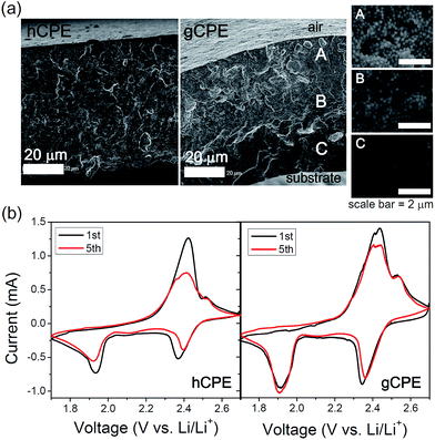
Cross-sectional morphologies of hCPE and gCPE were examined by scanning electron microscopy (SEM), which indicated dissimilar SNP distributions (Fig. 1a). Magnified images of three representative cross-sectional areas of gCPE, i.e., near air, center, and near substrate, are presented in the insets to demonstrate the position-dependence of the SNP densities, beneath the air-membrane interface. Interestingly, the ionic conductivity of gCPE is ca. 10% higher than that of hCPE (Fig. S3 of ESI†), implying that the distribution of SNPs within the CPEs impacts the Li+-ion transport efficiency. Therefore, it is inferred that the densely packed, negatively charged surfaces of SNPs provide a more efficient Li+-ion diffusion pathway. It is also noted here that the addition of SNPs in GPE resulted in the enhancement of conductivity (the lower conductivity of GPE than those of gCPE and hCPE, Fig. S3†). This indicates that the SNPs in CPEs should not hinder Li+-ion conduction path.
 | ||
| Fig. 1 (a) Cross-sectional SEM images of hCPE and gCPE. Three representative cross-sectional areas of gCPE are magnified in the insets. (b) Cyclic voltammetry of the Li/hCPE/S and Li/gCPE/S cells. | ||
After assembling coin cells containing the hCPE and gCPE electrolytes, a Li-metal anode, and sulfur in carbon black cathode, the cells were subjected to cyclic voltammetry (dense SNP side of gCPE was placed on the sulfur cathode). Representative data obtained from the Li/hCPE/S and Li/gCPE/S cells at a scan rate of 0.1 mV s−1 are compared in Fig. 1b. Two reduction peaks at 1.9 V and 2.4 V (vs. Li/Li+) and one oxidation peak at 2.4 V (and shoulder at 2.5 V) were clearly identified. While shifts in the locations of the reduction peaks and decreases in the peak currents were seen for the Li/hCPE/S cell during subsequent cycles, there were relatively small alterations in the peak locations or currents in the case of the Li/gCPE/S cell as a function of the number of cycles. This indicates the reduced tendency for the formation of a solid electrolyte interface on the cathode as well as intact active materials in the case of gCPE-based cells.
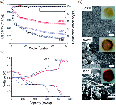
Fig. 2a presents the galvanostatic discharge/charge capacities of the Li/gCPE/S and Li/hCPE/S cells, cycled between 1.7–2.8 V at 0.5 C, at room temperature. The results of the Li/GPE/S cell, used as control, are also shown. The Li/gCPE/S cell showed an initial discharge capacity of 830 mA h g−1 (based on the sulfur content), which decreased to 500 mA h g−1 after 80 cycles with 100% Coulombic efficiency, corresponding to a capacity retention of 60% compared to the initial discharge capacity. This is in sharp contrast with the low discharge capacities and poor capacity retentions seen in the case of the Li/hCPE/S (240 mA h g−1, 28%) and Li/GPE/S (133 mA h g−1, 20%) cells under the same cycling conditions. The charge/discharge voltage profiles of the three Li–S cells obtained during the first cycle are shown in Fig. 2b, where plateaus at 2.0 V and 2.4 V (vs. Li/Li+) during discharging and at 2.4 V during charging were identified.
In the case of the Li/hCPE/S cell, we noticed that most of the capacity fading occurred during the first few cycles, implying a significant loss of active mass into the electrolyte. This result prompted us to elucidate the dependence of the extent of polysulfide dissolution on the CPE structure. The cathode side surface morphologies of gCPE, hCPE, and GPE were examined by SEM equipped with an energy-dispersive X-ray (EDX) spectroscopy. The electrolytes were separated from the Li–S cells after five discharge/charge cycles. As shown in Fig. 2c, the surface of gCPE was smooth with an insignificant amount of sulfur aggregates, in contrast with the large sulfur crystals seen for hCPE and GPE. This difference was also clearly seen with the naked eye, as shown in the insets in Fig. 2c. The amounts of sulfur on the surfaces of gCPE, hCPE, and GPE determined by EDX were 10, 16, and 27 wt%, respectively, indicating that the polysulfide intermediates are most effectively rendered impermeable by prevalent positioning of negatively charged SNPs near the cathode surfaces. This is likely to be responsible for the improved battery performance seen in the case of the Li/gCPE/S cell (Fig. 2a).
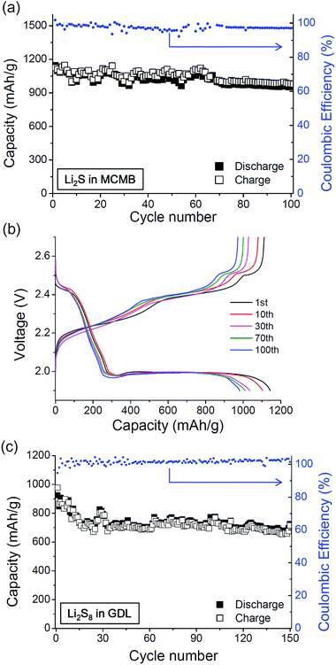
It has been proven that the use of optimized sulfur cathodes along with gCPE results in Li–S batteries with improved performance. Two types of sulfur cathodes, namely Li2S in MCMB (S-C) and Li2S8 catholyte in gas diffusion layer (S-GDL), were prepared and the discharge/charge cycle properties of the Li/gCPE/S-C and Li/gCPE/S-GDL cells at 0.2 C rate were examined. As shown in Fig. 3a, an improved cyclability was demonstrated by the Li/gCPE/S-C cell, where the battery still maintained a reversible specific discharge capacity of 970 mA h g−1 after 100 cycles, which is equivalent to 85% capacity retention. In Fig. 3b, representative voltage profiles of the Li/gCPE/S-C cell, cycled between 1.9 V and 2.7 V at room temperature are shown. An advanced cycle properties were also observed for the Li/gCPE/S-GDL cell, as shown in Fig. 3c. The specific discharge capacity of the Li/gCPE/S-GDL cell was 752 mA h g−1 after 100 cycles, corresponding to capacity retention of 81%. The cell delivered a reversible discharge capacity of 725 mA h g−1 after 150 cycles (capacity retention of 78%). The results presented above should be significant advances in Li/CPE/S batteries.
In summary, we have proposed a new design for CPEs with the goal of achieving improved Li–S battery cycle life. The exploitation of gCPE enabled us to attain a stable discharge capacity of 970 mA h g−1 after 100 cycles. The improved long-term cycle life is believed to be as a result of the strategic positioning of negatively charged SNPs near the cathode surfaces, in order to decelerate the dissolution of polysulfides into the CPE during battery cycling. To the best of our knowledge, this is the first work to unveil the important role played by the internal structure of the CPEs in determining the performance of Li–S cells.
Acknowledgements
This work was financially supported by the Global Frontier R&D program on Center for Multiscale Energy System funded by the National Research Foundation (NRF) of Korea under the Ministry of Education, Science and Technology.Notes and references
-
(a) Y. Li, B. Tan and Y. Wu, Nano Lett., 2008, 8, 265–270 CrossRef CAS PubMed
; (b) P. L. Taberna, S. Mitra, P. Poizot, P. Simon and J.-M. Tarascon, Nat. Mater., 2006, 5, 567–573 CrossRef CAS PubMed
; (c) H. Li, Z. Wang, L. Chen and X. Huang, Adv. Mater., 2009, 21, 4593–4607 CrossRef CAS
; (d) B. Scrosati, J. Hassounab and Y.-K. Sun, Energy Environ. Sci., 2011, 4, 3287–3295 RSC
.
-
(a) M. Armand and J.-M. Tarascon, Nature, 2008, 451, 652–657 CrossRef CAS PubMed
; (b) I. Choi, H. Ahn and M. J. Park, Macromolecules, 2011, 44, 7327–7334 CrossRef CAS
; (c) G. Jo, I. Choi, H. Ahn and M. J. Park, Chem. Commun., 2012, 48, 3987–3989 RSC
; (d) H. Wang, L.-F. Cui, Y. Yang, H. S. Casalongue, J. T. Robinson, Y. Liang, Y. Cui and H. Dai, J. Am. Chem. Soc., 2010, 132, 13978–13980 CrossRef CAS PubMed
; (e) B. Kang and G. Ceder, Nature, 2009, 458, 190–193 CrossRef CAS PubMed
.
-
(a) X. Ji, K. T. Lee and L. F. Nazar, Nat. Mater., 2009, 8, 500–506 CrossRef CAS PubMed
; (b) N. Jayaprakash, J. Shen, S. S. Moganty, A. Corona and L. A. Archer, Angew. Chem., 2011, 123, 6026–6030 CrossRef
.
-
(a) X. Ji, S. Evers, R. Black and L. F. Nazar, Nat. Commun., 2011, 2, 325 CrossRef PubMed
; (b) J. Gao, M. A. Lowe, Y. Kiya and H. D. Abruna, J. Phys. Chem. C, 2011, 115, 25132–25137 CrossRef CAS
.
-
(a) S. Xin, L. Gu, N.-H. Zhao, Y.-X. Yin, L.-J. Zhou, Y.-G. Guo and L.-J. Wan, J. Am. Chem. Soc., 2012, 134, 18510–18513 CrossRef CAS PubMed
; (b) S. Evers and L. F. Nazar, Acc. Chem. Res., 2013, 46, 1135–1143 CrossRef CAS PubMed
; (c) J. Guo, Z. Yang, Y. Yu, H. D. Abruña and L. A. Archer, J. Am. Chem. Soc., 2013, 135, 763–767 CrossRef CAS PubMed
.
-
(a) G. Zheng, Y. Yang, J. J. Cha, S. S. Hong and Y. Cui, Nano Lett., 2011, 11, 4462–4467 CrossRef CAS PubMed
; (b) S. Zhao, C. Li, W. Wang, H. Zhang, M. Gao, X. Xiong, A. Wang, K. Yuan, Y. Huang and F. Wang, J. Mater. Chem. A, 2013, 1, 3334–3339 RSC
; (c) S. Jiang, Z. Zhang, X. Wang, Y. Qu, Y. Lai and J. Li, RSC Adv., 2013, 3, 16318–16321 RSC
; (d) S. Lu, Y. Chen, X. Wu, Z. Wang, L. Lv, W. Qin and L. Jiang, RSC Adv., 2014, 4, 18052–18054 RSC
.
-
(a) J. Hassoun and B. Scrosati, Adv. Mater., 2010, 22, 5198–5201 CrossRef CAS PubMed
; (b) K. Jeddi, M. Ghaznavi and P. Chen, J. Mater. Chem. A, 2013, 1, 2769–2772 RSC
; (c) S. S. Zhang, J. Electrochem. Soc., 2013, 160, A1421–A1424 CrossRef CAS PubMed
; (d) S. S. Zhang and D. T. Tran, J. Mater. Chem. A, 2014, 2, 7383–7388 RSC
; (e) Z. Jin, K. Xie and X. Hong, RSC Adv., 2013, 3, 8889–8898 RSC
.
-
(a) R. C. Agrawal and G. P. Pandey, J. Phys. D: Appl. Phys., 2008, 41, 223001 CrossRef
; (b) C. Zhang, S. Gamble, D. Ainsworth, A. M. Z. Slawin, Y. G. Andreev and P. G. Bruce, Nat. Mater., 2009, 8, 580–584 CrossRef CAS PubMed
.
-
(a) W. Huang, Z. Zhu, L. Wang, S. Wang, H. Li, Z. Tao, J. Shi, L. Guan and J. Chen, Angew. Chem., 2013, 125, 9332–9336 CrossRef
; (b) J.-H. Park, J.-S. Kim, E.-G. Shim, K.-W. Park, Y. T. Hong, Y.-S. Lee and S.-Y. Lee, Electrochem. Commun., 2010, 12, 1099–1102 CrossRef CAS PubMed
.
-
(a) J.-H. Shin, W. A. Henderson and S. Passerini, J. Electrochem. Soc., 2005, 152, A978–A983 CrossRef CAS PubMed
; (b) P. P. Soo, B. Huang, Y.-I. Jang, Y.-M. Chiang, D. R. Sadoway and A. M. Mayes, J. Electrochem. Soc., 1999, 146, 32–37 CrossRef CAS PubMed
; (c) M. Singh, O. Odusanya, G. M. Wilmes, H. B. Eitouni, E. D. Gomez, A. J. Patel, V. L. Chen, M. J. Park, P. Fragouli, H. Iatrou, N. Hadjichristidis, D. Cookson and N. P. Balsara, Macromolecules, 2007, 40, 4578–4585 CrossRef CAS
.
-
(a) M. Deka and A. Kumar, Electrochim. Acta, 2010, 55, 1836–1842 CrossRef CAS PubMed
; (b) J. R. Nair, C. Gerbaldi, G. Meligrana, R. Bongiovanni, S. Bodoardo, N. Penazzi, P. Reale and V. Gentili, J. Power Sources, 2008, 178, 751–757 CrossRef CAS PubMed
; (c) S. S. Zhang and D. T. Tran, Electrochim. Acta, 2013, 114, 296–302 CrossRef CAS PubMed
.
-
(a) J. Jin, Z. Wen, X. Liang, Y. Cui and X. Wu, Solid State Ionics, 2012, 225, 604–607 CrossRef CAS PubMed
; (b) Z. Jin, K. Xie, X. Hong and Z. Hu, J. Power Sources, 2013, 242, 478–485 CrossRef CAS PubMed
.
-
(a) Y. Zhu, S. Xiao, Y. Shi, Y. Yang, Y. Hou and Y. Wu, Adv. Energy Mater., 2014, 4, 1300647 Search PubMed
; (b) K. Jeddi, Y. Zhao, Y. Zhang, A. Konarov and P. Chen, J. Electrochem. Soc., 2013, 160, A1052–A1060 CrossRef CAS PubMed
.
Footnote |
| † Electronic supplementary information (ESI) available: Experimental details, SEM & zetapotential of SNPs, FT-IR of CPEs, ionic conductivities of CPEs and GPE, and Nyquist plots of the Li–S cells. See DOI: 10.1039/c4ra12657b |
| This journal is © The Royal Society of Chemistry 2014 |


