
The importance of sulfonate to the self-doping mechanism of the water-soluble conjugated polyelectrolyte PCPDTBT-SO3K†
David Xi
Cao
a,
Dirk
Leifert
b,
Viktor V.
Brus
a,
Matthew S.
Wong
a,
Hung
Phan
c,
Brett
Yurash
a,
Norbert
Koch
d,
Guillermo C.
Bazan
 *a and
Thuc-Quyen
Nguyen
*a
*a and
Thuc-Quyen
Nguyen
*a
aCenter for Polymers and Organic Solids, Department of Chemistry and Biochemistry, University of California, Santa Barbara, California 93106, USA
bInstitute of Organic Chemistry, University of Münster, Corrensstraße 40, 48149 Münster, Germany
cFulbright University Vietnam, Floor 2, Crescent Plaza, 105 Ton Dat Tien, Tan Phu Ward, District 7, Ho Chi Minh City, Vietnam
dSupramolecular Systems, Integrative Research Institute for the Sciences, Department of Physics, Humboldt University, Brook-Taylor-Straße 6, 12489 Berlin, Germany
First published on 26th March 2020
Abstract
The conjugated polyelectrolyte poly[2,6-(4,4-bis-potassium butanylsulfonate-4H-cyclopenta-[2,1-b;3,4-b′]-dithiophene)-alt-4,7-(2,1,3-benzothiadiazole)] (PCPDTBTSO3K, or CPE-K) is part of a unique class of organic semiconducting polymers that are soluble in water and become doped in the presence of a proton source. One of these proton sources is water, which CPE-K is exposed to during purification by dialysis, allowing for its immediate use without an additional doping step. Previous studies have suggested that the actual dopant is H+, and that the addition of sodium hydroxide to CPE-K reverses the process and de-dopes the polymer. Curiously, the majority of these water-soluble self-doped polymers in the literature contain a pendant sulfonate group. However, a detailed study to gain insight into the importance of the sulfonate group in water-soluble self-doped polymer systems is lacking, despite its widespread presence in the literature. In this work, using Fourier-transform infrared spectroscopy (FTIR), X-ray photoelectron spectroscopy (XPS), and ultraviolet-visible-near infrared (UV-vis-NIR) absorption spectroscopy, we are able to elucidate the role of the pendant sulfonate group with regards to the fundamental doping mechanism of CPE-K. Specifically, we found the CPDT unit can be protonated by water, which is due to both the stabilizing influence of the sulfonate group, and the relatively high oxidation potential of the CPDT unit, both of which are required for self-doped water soluble polymer systems. Furthermore, we estimate the doping efficiency of CPE-K using electrical measurements and X-ray reflectivity (XRR), and reveal several different methods for the doping and de-doping of this material, showcasing this particular material's superior versatility.
Introduction
Doping of organic polymers was first realized in the 1970s with halogen vapor and alkali metals.1–4 With their doped organic polymers, the authors were able to create p–n junctions and realize the first organic electronic device. However, such harsh dopants are unstable, and they could not be used to controllably modulate the charge carrier concentration. Because of this, the field of organic electronics turned to more stable molecular dopants such as 2,3,5,6-tetrafluoro-7,7,8,8-tetracyanoquinodimethane (F4TCNQ) in order to precisely control doping levels.5–10 Aside from F4TCNQ, another dopant that is not as widely used but that was discovered in the late 1980s is the proton.11 Neher et al. showed how a range of polymers could be doped by Brønsted acids, and how, more importantly, acid strength and ionization potential dictate whether or not a specific polymer would be doped by a specific acid.7 Another study showed how polymers containing pendant ionic groups and counter-ions would lose their counter-ions to the solution upon oxidation of the polymer. Loss of counter-ions is due to the pendant ionic groups stabilizing the hole present on the polymer backbone, thus eliminating the need for counter-ions.12 However, neither paper studied self-doping polymers, nor did their studies correlate electronic properties and their doping efficiency with their structural changes that occur during doping. While the authors show that sulfonate is necessary for the acid doping of these polymer systems, how the sulfonate group plays a role has not yet been determined.Conjugated polyelectrolytes (CPEs) are unique polymers as they contain a π-conjugated backbone and pendant ionic groups which make the polymer soluble in water and polar solvents.13,14 Pendant anionic side chains have also been shown to give CPEs the ability to be self-doped during purification in water, eliminating an extra processing step and the use of additional chemicals typically used in doping neutral conjugated polymers.15 This self-doping property eliminates the need for adding external dopants such as F4TCNQ, which has a low solubility in organic solvents, often aggregates and prevents the doping of organic semiconductor materials to conductivity levels necessary for use in various device applications. Specifically, CPE-K has been shown to be doped in the mildly acidic conditions of ultrapure H2O (Ω = 18.3 MΩ cm), and is de-doped via the addition of a base. These properties allow user tunability of the doping level by adding the desired amount of acid or base, which is an important feature as precise control of the doping level is at the heart of modern electronics. Previous work on the study of doping in CPE-K has also shown that doping occurs in the presence of acid vigorously sparged to remove all the oxygen, which agrees with Han and Elsenbaumer's work.16 CPEs have been used in a wide variety of applications such as biosensors, as an interlayer or a conductive buffer layer in organic and perovskite photovoltaics, as an interconnective layer between top and bottom cells in tandem organic solar cells, as the active layer in light-emitting electrochemical cells, to modify the injection barrier in OFETs, and in organic thermoelectrics.17–34 CPEs have also been recently shown to act as p- or n-type dopants for carbon nanotubes, a property that is modulated by changing the charge of the ionic groups of the CPEs.17 CPE/graphene hetero-bilayer 2D nanocomposites also exhibit a unique, temperature switchable type of electrical conductivity.35 In summary, the ability to control the conductivity of CPEs, to dope the material during the purification, and its pH neutral character can open the door to its use in a wide range of electronic and optoelectronic device applications from organic field effect transistors (OFETs) to organic photovoltaics (OPVs) and everything else in-between. Yet, a more comprehensive understanding of the importance of sulfonate for the self-doping mechanism of CPE-K and its effect on charge transport and mobility is required to improve the use and design of this class of polymers. We aim to shed light on the role that pendant sulfonate groups play in the self-doping of this class of polymers through probing doped and un-doped state of CPE-K with X-ray photoelectron spectroscopy (XPS), Fourier-transform infrared spectroscopy (FTIR), and ultraviolet-visible-near infrared spectroscopy (UV-vis-NIR) absorption spectroscopy. In addition, we study the material's electrical properties in the doped and un-doped states via a series of electrical measurements. We also provide an estimate of the doping efficiency, and show another, unique method for the reversible doping and de-doping of this material.
Results and discussion
Structure of doped and de-doped CPE-K.
Fig. 1 shows the proposed doped and un-doped chemical structures of CPE-K, which was previously synthesized by Bazan et al. and reported to have a molecular weight of approximately 8000 g mol−1 with a PDI of 1.05.15 Based on the below structures, several structural and chemical changes such as the reduction in potassium concentration and change in vibrational structure in the conjugated backbone of CPE-K should be noticeable upon doping. | ||
| Fig. 1 Proposed schematic representation for protonic acid doping of CPE-K, including hypothesized transient intermediates that follow step 1 and step 2. The system can then undergo single electron transfer (SET) to arrive at the final species. | ||
More specifically, upon protonation of the cyclopentadithiophene (CPDT) unit of the polymer, a cation is formed in the conjugated backbone of the polymer. A neutral polymer chain can then undergo single electron transfer with the protonated polymer giving one polymer chain with a positive polaron and another polymer chain with an unpaired electron. This structural change will result in additional vibrational peaks for both polymer chains due to a loss in rigidity in the polymer backbone, which was previously enforced by the unbroken chain of sp2 hybridized carbons in the backbone. The additional vibrational freedom experienced by the polymer results in new vibrational modes that are revealed through infrared spectroscopy. In addition, when doping occurs, the SO3− groups stabilize the radical cations (positive polarons or holes) on the backbone, thus eliminating the need for the K+ counterions, a change that is detectable by XPS. While the K+ ions are necessary to stabilize the SO3− groups in the undoped state of CPE-K, the K+ ions are no longer necessary after the formation of holes on the polymer backbone and are likely solvated away by water molecules in solution. In the following sections, please note that “self-doped CPE-K” solution was prepared by dissolving the polymer in water and all “doped with H2SO4” and “de-doped CPE-K” solutions were prepared by the addition of 1 mole equivalent per sulfonate group of either H2SO4 or KOH to a solution of self-doped CPE-K.
X-ray photoelectron spectroscopy (XPS)
In the XPS analysis of CPE-K, we first start with CPE-K that has been de-doped by the addition of KOH to the self-doped CPE-K solution. When looking at the C 1s and K 2p high resolution spectrum, in theory de-doped CPE-K should have a 2![[thin space (1/6-em)]](https://www.rsc.org/images/entities/char_2009.gif) :25 potassium to carbon atom ratio. However, XPS analysis of CPE-K in Fig. 2 reveals a K 2p signal corresponding to a potassium to carbon atom ratio of approximately 4:25 in undoped CPE-K, which can be attributed to the addition of KOH beyond what was needed to de-dope the CPE-K solution. One equivalent of KOH was added per sulfonate group; however, it is possible that the amount of KOH needed to de-dope the polymer was less than 1.0 equivalent of KOH per sulfonate group resulting in the higher than expected K 2p percentage seen in XPS. In addition, very small crystallites of salt were seen on the surface of the film under magnification, suggesting the formation of KOH crystals that would explain the higher than expected K 2p signal. Washing the film with water in order to remove the salt crystals from the film would then also dissolve the film, thus XPS analysis was performed on the sample as is after spin casting. Upon doping of CPE-K, there is a clear reduction in the ratio of potassium to carbon as expected from 4:25 in dedoped CPE-K to 1:25 in CPE-K self-doped in H2O, and to 0.4:25 in CPE-K doped with H2SO4 (Table 1). A table with a summary of all the atomic percentages of the elements measured in the CPE-K film is included in the ESI† as Table S1, which shows the reduction in potassium percentage upon increased doping level. In support of this observation, there is also a concomitant increase in the percentages of oxygen and sulfur, suggesting the presence of SO42− and HSO4− counterions following protonation of the polymer backbone by H2SO4. With an increase of holes in the backbone, the potassium ion is no longer needed to compensate for the pendant sulfonate groups as the sulfonate balances out the hole on the backbone (Table 1).
:25 potassium to carbon atom ratio. However, XPS analysis of CPE-K in Fig. 2 reveals a K 2p signal corresponding to a potassium to carbon atom ratio of approximately 4:25 in undoped CPE-K, which can be attributed to the addition of KOH beyond what was needed to de-dope the CPE-K solution. One equivalent of KOH was added per sulfonate group; however, it is possible that the amount of KOH needed to de-dope the polymer was less than 1.0 equivalent of KOH per sulfonate group resulting in the higher than expected K 2p percentage seen in XPS. In addition, very small crystallites of salt were seen on the surface of the film under magnification, suggesting the formation of KOH crystals that would explain the higher than expected K 2p signal. Washing the film with water in order to remove the salt crystals from the film would then also dissolve the film, thus XPS analysis was performed on the sample as is after spin casting. Upon doping of CPE-K, there is a clear reduction in the ratio of potassium to carbon as expected from 4:25 in dedoped CPE-K to 1:25 in CPE-K self-doped in H2O, and to 0.4:25 in CPE-K doped with H2SO4 (Table 1). A table with a summary of all the atomic percentages of the elements measured in the CPE-K film is included in the ESI† as Table S1, which shows the reduction in potassium percentage upon increased doping level. In support of this observation, there is also a concomitant increase in the percentages of oxygen and sulfur, suggesting the presence of SO42− and HSO4− counterions following protonation of the polymer backbone by H2SO4. With an increase of holes in the backbone, the potassium ion is no longer needed to compensate for the pendant sulfonate groups as the sulfonate balances out the hole on the backbone (Table 1).
 | ||
| Fig. 2 High resolution XPS spectra of (a) C 1s and K 2p3/2, (b) N 1s, and (c) S 2p3/2 and their Voigt fitting profiles of CPE-K w/H2SO4 added, self-doped CPE-K, and de-doped CPE-K on ITO with a film thickness of 20 nm. Black dots are experimental data and the colored lines are overall fits obtained with a peak-fitting routine. | ||
| CPE-K | K:C |
C–N | C–S | C–C | C![[double bond, length as m-dash]](https://www.rsc.org/images/entities/char_e001.gif) C C |
|---|---|---|---|---|---|
| Doped w/H2SO4 | 0.4:25 |
2.1 | 5.9 | 6.8 | 8.1 |
| Self-doped in H2O | 1:25 |
1.9 | 5.9 | 7.0 | 8.2 |
| De-doped w/KOH | 4:25 |
1.9 | 5.9 | 7.0 | 8.2 |
| Wavenumber [cm−1] | Bond/group assignment |
|---|---|
| 1635 | Benzothiadiazole/H2O |
| 1517 | CN ring stretch, benzothiadiazole |
| 1459 | sp3 C asymmetric vibration CPDT |
| 1390 | CPDT/benzothiadiazole |
| 1300 | C–C asymmetric CPDT stretch |
| 1169 | Asymmetric SO3− stretch |
| 1041 | Symmetric SO3− stretch |
Protons from H2SO4 can also undergo an ion exchange reaction with potassium – the pKa of H2SO4 is approximately −3.0 while the pKa of the sulfonate moiety is >−2.6 allowing for such an ion exchange process to occur. To ensure the reduction in potassium percentage correlates with the addition of holes into CPE-K, we obtained additional high resolution XPS data of the XPS peaks in the C 1s and K 2p region of CPE-K before the final purification step in water, which means CPE-K has not yet been doped by water. Indeed, in the XPS spectrum in Fig. S1 (ESI†), we see that un-doped CPE-K, whether before purification in water or after the addition of base to de-doped CPE-K, results in the same ratio of K to C atoms as measured by XPS. Table S2 (ESI†) provides a quantification summary of the data from Fig. S1 (ESI†). Lastly, the doublet K 2p3/2 peak at 293.2 eV and the K 2p1/2 peak 296.0 eV agree with reported binding energies for K+ from the National Institute of Science and Technology (NIST) database.36
For the carbon signals, all of the C 1s high resolution peaks in Fig. 2a were fit with four Voigt profiles consistent with four inequivalent carbons on CPE-K. The peak at 284.8 eV corresponds to carbons within the conjugated backbone that are bonded to other carbons (CC), the peak at 285.0 eV corresponds to carbons on the alkyl chain that are bonded to other carbons (C–C), the peak at 285.7 eV corresponds to carbons bonded to sulfur atoms (C–S), and the peak at 286.9 eV corresponds to carbons bonded to nitrogen atoms (C–N), as expected from the chemical structure and previously described in literature.37 From the chemical structure, given the amount of each of these types of carbons in CPE-K, we expect a peak intensity ratio for CPE-K of 2:6:7:8 (C–N, C–S, C–C, CC), which was indeed the ratio obtained from peak fitting (Table 1). The carbon peak at 289.2 eV is due to a shake-up satellite, which appears due to the energy loss of a photoelectron that has induced a π → π* excitation during final state formation.38,39
The nitrogen high-resolution XPS spectra in Fig. 2b shows one peak at 399.5 eV corresponding to the two chemically equivalent nitrogen atoms bound to a sulfur in undoped CPE-K, whereas the addition of holes into the backbone upon self-doping in H2O results in the formation of higher binding energy peaks at 400.2 eV and 401.6 eV. The higher binding energy nitrogen peak at 400.2 eV corresponds to a radical cation nitrogen, as expected due to the presence of holes that appear after doping CPE-K. The peak at 401.6 eV is tentatively assigned to shake-up satellites, which typically appear a few eV higher in binding energy than the main element peak with an intensity of approximately 10% that of the main peak.39,40 Upon further doping by the addition of H2SO4, an even higher binding energy peak appears at 402.2 eV, which corresponds to the protonation of the imine nitrogen in CPE-K by excess H2SO4.41,42 As it was the case with the addition of KOH, it is likely the addition of H2SO4 is performed beyond 1.0 equivalent per CPE-K sulfonate since CPE-K is already self-doped.
In the undoped CPE-K S 2p spectrum, we can identify three chemically inequivalent sulfur atoms, as expected, with the 3/2 spin–orbit component peaking at 164.0 eV, 165.4 eV, and 168.1 eV binding energy (all doublets split by 1.18 eV with a 2:1 area ratio). The highest binding energy sulfur peak at 168.1 eV belongs to the sulfur on the sulfonate group as it is the most electron poor sulfur atom, while the sulfur at 165.4 eV belongs to the benzothiadiazole unit. The lowest binding energy sulfur peak at 164.0 eV belongs to the thiophene, which is the most electron rich of the three sulfur atoms.37,43,44
Upon doping of CPE-K, additional peaks appear in the S 2p spectra. The peak centered at 166.5 eV can be attributed to more positively charged sulfur atoms in thiophene, while the peak centered at 170 eV is likely due to less electrostatically screened sulfur in the sulfonate ions. After the addition of 1.0 equivalent of H2SO4 per sulfonate group, an additional peak at a higher binding energy, i.e., 169.3 eV, appears as expected from a sulfur bound to four oxygen atoms, while also increasing the area percentages of the peaks belonging to electron deficient sulfur atoms on the polymer located at 165.9 eV and 169.0 eV, respectively, due to the increased doping. We attribute the overall higher binding energy of these sulfur species, compared to de-doped and self-doped samples, to different electrostatic interactions, as K cations seemingly better screen the sulfonate and polaron charges compared to the positive polarons, in accord with the different Madelung potentials of the differently doped polymers.45 An even higher binding energy peak located at 169.9 eV is attributed to negatively charged sulfonate ions, whose electrostatic interaction with the protonated CPE-K polymer chains is particularly weak. As mentioned above, additional acid could have caused protonation beyond what could be stabilized by the sulfonate groups on CPE-K, resulting in CPE-K polymer chains with an overall positive charge that allow for an electrostatic interaction with SO42− to occur.46 This electrostatic interaction of the polymer chains causes increased polymer density and increased viscosity of the CPE-K polymer chains, which is supported by the observed thickening of the CPE-K solution upon addition of sulfuric acid to the CPE-K solution. Additional doping of CPE-K via addition of 1 monomeric equivalent of H2SO4 to the solution reduces the solubility by about half. Lastly, a survey scan of CPE-K after purification shows signals from only the elements expected from the chemical structure of CPE-K (Fig. S2, ESI†).
Attenuated total reflectance-Fourier transform infrared spectroscopy (ATR-FTIR)
ATR-FTIR spectroscopy was used to investigate vibrational level changes in the polymer upon exposure of CPE-K to various sources of protons. Focusing on the fingerprint region of the IR spectra, which were obtained by drop casting solutions of CPE-K at various doping levels directly onto the ATR crystal, it is immediately clear that the spectrum of doped CPE-K contains an additional peak at 1300 cm−1 that the undoped CPE-K does not possess (Fig. 3). In addition, CPE-K that has been annealed also does not have the peak at 1300 cm−1, a finding which is discussed further below in the section on reversible de-doping and doping of CPE-K by annealing. | ||
| Fig. 3 ATR-IR spectrum and corresponding functional group vibrations denoted by color on the chemical structure on the right. | ||
The peak at 1300 cm−1 is a crucial indicator of the doped CPE-K species, and it was assigned to an asymmetrical C–C stretch between the CPDT and benzothiadiazole (BT) portions of the CPE-K polymer. This peak at 1300 cm−1 only appears upon protonation of the CPDT unit.47 Protonation of the CPDT unit at the location indicated by the red hydrogen in Fig. 1 breaks the conjugation between the BT and CPDT units leading to an increase in vibrational freedom and the appearance of the new peak. Han and Elsenbaumer also suggested such a reaction occurs based on 13C NMR data.11
In addition, the broad peak at 1200 cm−1 belongs to the asymmetrical SO3− stretch, which shifts to lower wavenumber upon increased levels of CPE-K doping. This is consistent with our hypothesis that SO3− is no longer interacting with the potassium counterion, but instead with a hole on the conjugated backbone of CPE-K, which was previously only hypothesized, but not proven. An interaction between the negatively charged oxygens of the sulfonate group with the hole on the backbone would be more favorable from an atomic radii standpoint, and the hole on the backbone would draw out the oxygen away from the sulfur, leading to a longer S–O bond length and hence lower wavenumber (Table 2).
UV-vis and electrical measurements
To ensure the material being analyzed is doped, which we take here to mean there is an increase in charge carriers which may participate in charge transport, we performed electrical measurements and coupled those with UV-vis-NIR absorption characterization (Fig. 4). The peak at 410 nm corresponds to π–π* absorption from localized π orbitals, while the higher intensity peak at 690 nm corresponds to the absorption from the intra-charge transfer (ICT) band.16 The two lower energy peaks at 1100 nm and 2000 nm, respectively, are due to the formation of positive polarons on the polymer backbone.48,49 The UV-vis-nIR absorption spectrum was fit for both the main electronic transitions as well as the polaron peaks and are shown in Fig. S3 (ESI†). Quantification of the peak areas are shown as percentages in Table S3 (ESI†). We also obtained solution UV-vis-nIR absorption spectra of the polymer where we substituted out both of the pendant ionic side chains with two simple linear C16-alkyl side chains (Fig. S4, ESI†). When the polymer consists of simple linear C16-alkyl side chains as opposed to the sulfonate group, there is no doping upon addition of even 1000 monomeric equivalents of MilliQ water to the polymer, highlighting again the important role the sulfonate moiety plays in self-doping of CPE-K during purification of the material. | ||
| Fig. 4 UV-vis-NIR absorption spectra of CPE-K films at various levels of doping, normalized using the peak at 410 nm. | ||
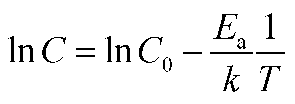
Temperature dependent conductivity measurements of CPE-K were performed using a parallel plane diode structure, with a channel length of 160 μm, and gold electrodes, which match the ionization energy of CPE-K thereby allowing for efficient charge injection into the material from the electrodes. By plotting the natural log of conductivity against inverse temperature to give the slope, the activation energy Ea was obtained by using eqn (1)
 | (1) |
| CPE-K | Activation energya [eV] | Conductivityb [S cm−1] | Mobility, μ [cm2 V−1 s−1] |
|---|---|---|---|
| a Planar two-point probe temperature dependent I–V measurement. b Planar two-point probe measurement. c Hall effect measurement. d Hole-only diode measurement. | |||
| w/H2SO4 | 0.117 ± 0.007 | 0.140 ± 0.019 | 0.30c |
| Self-doped in H2O | 0.159 ± 0.001 | 0.030 ± 0.003 | 0.24c |
| De-doped w/KOH | 0.272 ± 0.007 | Below detection limit | 2 × 10⁻⁸d |
Estimation of CPE-K doping efficiency
From both the aforementioned electrical and optical measurements, the material's doping efficiency – that is, the number of free charge carriers generated per dopant molecule – can be estimated. In traditional doped organic semiconductors that use dopants such as F4TCNQ, which are known to undergo 1:1 integer charge transfer with the organic semiconductor, it is straightforward to know the number of dopant molecules added to the system. However, as outlined above, the dopant for CPE-K is protons, and as a result, doping efficiency is a lot trickier to calculate and depends on additional factors such as molar concentration of CPE-K, proton concentration, and volume of solution.
In this manuscript, doping efficiency was estimated by obtaining an estimate of the monomer density in a film of CPE-K along with an estimate of the free charge carrier density, then taking a ratio of the two values. The density of CPE-K, obtained by X-ray reflectivity, was measured to be 1.30 g cm−3. Given the molar mass of a single monomer unit of CPE-K of 722.10 g mol−1, the estimated monomer density in the film was obtained to be 1.08 × 10²¹ monomers per cm3. By then using the conductivity and mobility values measured, the free charge carrier density can be obtained using eqn (2)
| σ = nqμ | (2) |
Reversible de-doping and doping of CPE-K by annealing
In this study, all the undoped CPE-K measurements were performed with CPE-K that has been de-doped through the addition of base, specifically KOH. However, there is another way to de-dope the polymers: via thermal annealing. Thermally assisted de-doping of a conductive polymer has also been seen in sulfonic acid ring-substituted polyaniline, in which the proposed mechanism was elimination of some sulfonic acid groups.42 In that particular case, the authors Chen and Hwang claimed the thermally assisted de-doping was partly irreversible due to a change in the chemical structure of the conjugated backbone. In another example using a sulfonated derivative of polythiophene, the authors also see thermal de-doping – however in this case the de-doping is completely irreversible due to decomposition of the polymer.53 In the case of CPE-K, thermal de-doping is a reversible process as explained below. One of the reasons for this is heating the CPE-K film up to 300 °C does not cause the loss of sulfonate groups as seen in thermal gravimetric analysis-mass spectrometry (TGA-MS) data, suggesting the mechanism for de-doping of the CPE-K film does not involve the loss of sulfonate side groups as that ion is not seen in the mass spectrum. Residual water in the film is driven off during annealing as seen from the TGA-MS data up until temperatures above 450 °C, at which point the CPE-K film degrades leading to the oxidation of the polymer into carbon dioxide (Fig. S6, ESI†). No other products are evolved during the entire TGA-MS run aside from water up until 300 °C. As seen in Fig. 5, annealing CPE-K for 30 minutes under a nitrogen atmosphere results in a reduction of the polaron absorption band of the polymer with increasing temperatures as monitored by UV-vis-nIR absorption spectroscopy.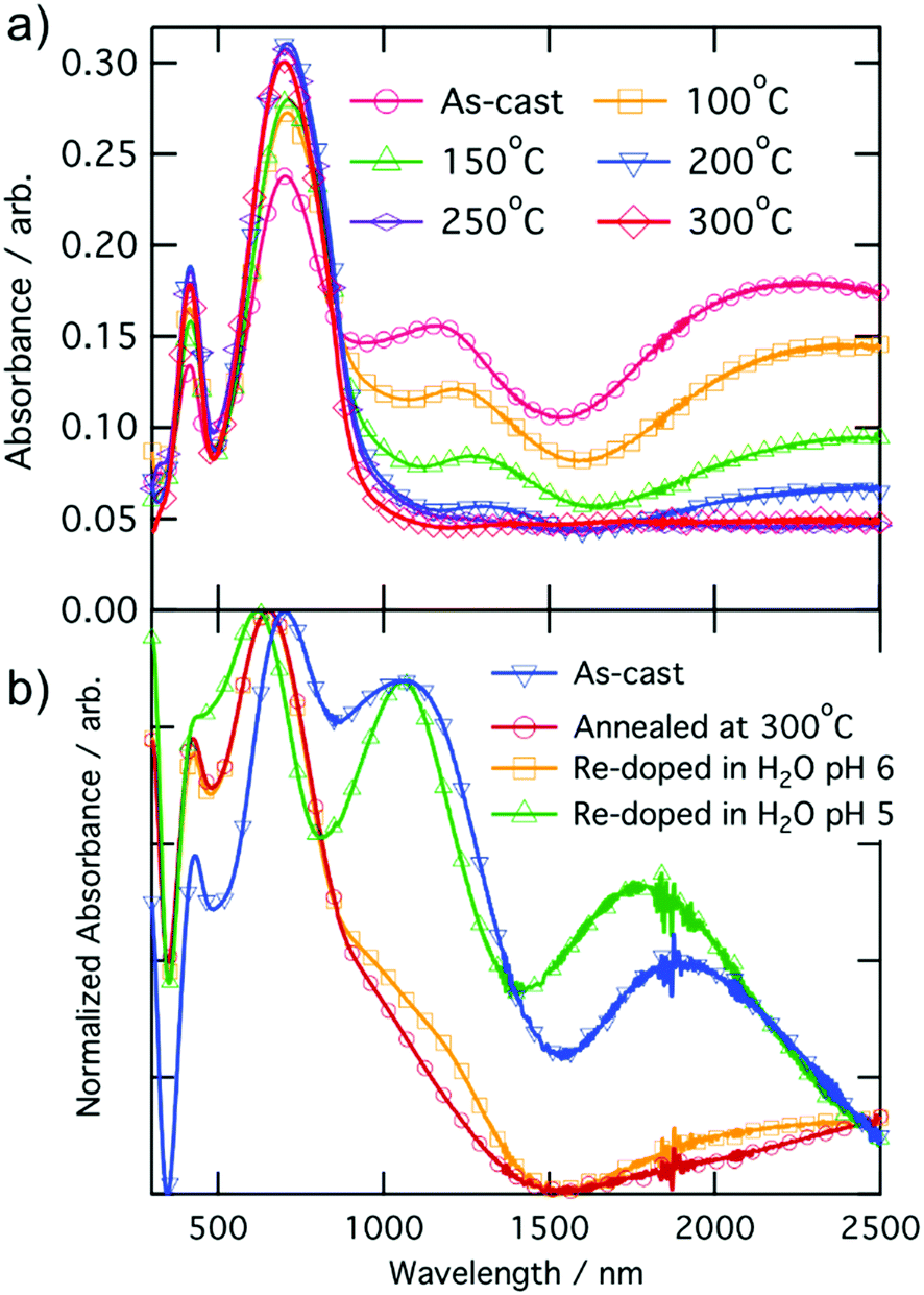 | ||
| Fig. 5 UV-vis-nIR absorption spectra of CPE-K with (a) annealing for 30 minutes and (b) after re-doping the film under oxygen-free conditions, normalized to peak at ∼690 nm. | ||
IR spectroscopy of an annealed CPE-K film also shows the same vibrational structure as seen in CPE-K de-doped by KOH (Fig. 3), which means CPE-K before doping and CPE-K that has been de-doped via thermal annealing result in the same chemical structure. In addition, the lack of a strong absorption at 1635 cm−1 in the post-annealed spectrum of CPE-K corresponds to the loss of H2O. De-doping of CPE-K through loss of water can also be seen in various I–V measurements both in nanoscale and in bulk measurements. Nanoscale I–V measurements are obtained via conductive atomic force microscopy (c-AFM), which operates by applying a bias to the conductive substrate, in this case indium tin oxide, while raster scanning a gold or platinum/chromium coated silicon AFM tip in contact mode across the surface of the sample. In doing so, a morphology and current image of the thin film can be obtained simultaneously, allowing for precise mapping of the morphology and current of semiconductor films. C-AFM measurements of CPE-K annealed for 30 minutes, at the same temperatures used for UV-vis-nIR absorption, show a decrease in the average current across the film (Fig. S7 and S8, ESI†) with no difference in surface morphology. Seeing a decrease in average current across the film without a change in the surface morphology is important as it means the reduced current in the film is due to the aforementioned changes in chemical structure and composition, and not on film surface morphology. Increasing the temperature of an as-cast film under vacuum while measuring bulk I–V curves across two parallel plane electrodes, set in the same configuration as were used for temperature dependent conductivity measurements above, shows a slight increase in the current until 147 °C, at which point the current decreases. Allowing the film to sit at 147 °C under a vacuum of 1 × 10⁻⁹ Torr overnight dramatically reduces the current seen in the film when analyzed the following day (Fig. S9, ESI†). By briefly submerging a CPE-K film that has been annealed at 300 °C in vigorously degassed water of pH = 5 or lower under oxygen-free conditions in an anaerobic chamber, the polaron signature returns in the UV-vis-nIR absorption spectrum in Fig. 5 without dissolving the polymer. Signals corresponding to the mass of SO2 and SO are evolved from the polymer at temperatures starting around 300 °C (Fig. S10, ESI†). This suggests the crosslinking of some, but not all of the CPE-K polymer chains via the sulfonate moiety in a Friedel–Crafts type addition reaction, reducing the overall water uptake efficiency throughout the bulk of the film thereby making it resistant to dissolution in water.54 This experiment also shows that the presence of oxygen is not required for doping of CPE-K. However, leaving the polymer in water for a longer amount of time (>5 minutes) will result in its dissolution. This thermally activated, reversible de-doping process is in itself an interesting finding, opening CPE-K to additional versatility in devices which require biological applications.
Experimental
Solution preparation
CPE-K solutions were prepared by dissolving previously doped CPE-K into Millipore H2O, and sonicating the solution until the solids were dissolved. An equal volume of methanol was added to give a 10 mg mL−1 CPE-K solution which was further sonicated, then filtered through a 0.45 μm PTFE filter before use. To obtain undoped CPE-K, 1.0 equivalent of KOH relative to the concentration of the monomer unit was added to the solution before use. To obtain “w/H2SO4” solutions, 1.0 equivalent of H2SO4 relative to the concentration of monomer unit was added to the solution before use. Both the KOH and H2SO4 solutions were at a concentration of 2.19 M.X-ray photoelectron spectroscopy (XPS)
All X-ray photoelectron spectroscopy measurements were obtained on using a Kratos Axis Ultra DLD XPS under vacuum (10−8 Torr) using monochromated X-rays produced using an aluminum source running at a potential of 14 kV. A pass energy of 20 was used for all high-resolution element sweeps. The CPE-K samples were spuncast onto cleaned conductive indium tin oxide/glass substrates. The films were mounted onto a sample bar using double-sided tape, and electrically grounded to the sample bar using nickel impregnated tape. Peak fitting was performed using WINSPEC, and atomic sensitivity factors for each element were taken into account during peak integrations.Attenuated total reflectance Fourier-transform infrared spectroscopy (ATR-FTIR)
Infrared spectroscopy measurements were obtained on a Thermo Nicolet iS10 FTIR Spectrometer by drop-casting the CPE-K solution and allowing it to dry before measurement. A baseline correction was performed on the data.Electrical measurements
All electrical measurements with the exception of the Hall effect measurement were performed under vacuum (10−7 Torr) using a Keithley 4200 semiconductor analyzer. Conductivity values were obtained by linear four-point probe measurement. The geometrical parameter S of the electrodes with a 200 μm channel length is 1.3 × 10⁻⁴, allowing for calculation of σ by eqn (3)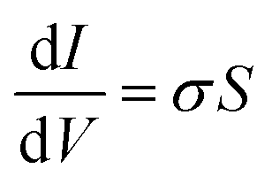 | (3) |
Conductive-atomic force microscopy (cAFM)
All topographic and current measurements were obtained using an Asylum MFP-3D operating in closed loop mode mounted atop an Olympus inverted optical microscope under an inert atmosphere. Pt/Cr coated silicon AFM tips with a resonant frequency of ∼13 kHz and a force constant of ∼0.2 N m−1 were used (Budget Sensors). All images were obtained at a force of 2 nN to ensure a constant electric field across all measurements. First order image flattening was performed on the morphology images on Asylum Research AFM software version 10, programmed using IGOR Pro.Thermogravimetric-mass spectrometry (TGA-MS)
Themogravimetric-mass spectrometry analyses were performed on a Discovery TGA housed at University of California, Santa Barbara's TEMPO facility, located within the materials research laboratory (MRL). 5.8 mg of CPE-K was placed in an AlO2 crucible, which was placed onto a high-temperature platinum pan, and analyzed under a nitrogen atmosphere. Temperature ramps were performed at a speed of 10 °C min−1. Mass spectrometry data was collected using Process Eye software. TGA data was collected using TRIOS, and analyzed along with MS data using TRIOS, developed by TA Instruments.UV-vis-nIR absorption
All UV-vis-nIR absorption spectra were obtained using a PerkinElmer Lambda 750 UV-vis-nIR absorption spectrometer using a tungsten lamp for the visible to near-IR region and a deuterium lamp for the UV region. A 100% transmission blank was obtained using a clean indium tin oxide/glass substrate for all spectra. The polymer PCPDTBT-C16 used as described in the section of UV-vis-nIR absorption in the main text was obtained from 1-Material.X-ray reflectivity (XRR)
Solution of CPE-K self-doped in H2O was spuncast on a clean glass substrate to obtain a thin film of approximately 25 nm. The density of the CPE-K thin film was then determined by X-ray reflectivity measurements using a Rigaku Smartlab High-Resolution Diffractometer and accompanying reflectivity fitting software (GXRR3).Conclusions
While the importance of having a pendant sulfonate side chain in the polymer for self-acid doping is known and recognized, the question of why it is necessary was unclear. With this work, we bring about a much better understanding of the importance of sulfonate and its role in the self-acid doping mechanism of CPE-K. By FTIR, we see new vibrational structures in the backbone that are consistent with increased rotational freedom of the CPDT unit due to protonation of CPDT, as well as a shift in the sulfonate peak, indicative of its role in stabilizing the polaron on the backbone. In addition, from the XPS data, we see a reduction in the K 2p peak with an increase in concentration of holes on the polymer backbone, which is consistent with sulfonate stabilizing the hole that is formed as the potassium counterion is no longer needed. The doping efficiency of CPE-K was also estimated, and though the doping efficiency is low, the mobility and conductivity of doped CPE-K is high. Given also the fact that water is a ubiquitous solvent, CPE-K in a wide range of organic optoelectronic devices. In addition, the findings reveal that doping of CPE-K can be reversed by both heat and addition of a base, allowing for its use in a wide variety of applications including as a heat sensor and as a hole transporting layer to replace PEDOT:PSS in OLEDs, organic solar cells, and organic photodetectors. This work will help guide the synthetic design of new, highly conductive CPEs. Specifically, from this work we show the importance of having an electron-rich structural unit on the polymer that can be oxidized easily, as well as the necessity of having a pendant anionic group to stabilize the resulting positively charged backbone for self-doped polymer systems. This work also provides the experimental layout that is anticipated to promote efforts for conducting future studies on this class of materials.Conflicts of interest
There are no conflicts to declare.Acknowledgements
D. X. C. acknowledges support by the National Science Foundation Graduate Research Fellowship Program under Grant No. 1650114. Any opinions, findings, and conclusions or recommendations expressed in this material are those of the authors and do not necessarily reflect the views of the National Science Foundation. The authors thank the Department of Energy (Award no. DE-SC0017659) for their support in understanding the doping mechanism. CPE-K synthesis was supported by the Institute of Collaborative Biotechnologies under Grant No. W911F-09-D-0001 from the U.S. Army Research Office. TGA-MS, FTIR, XPS, and XRR data was obtained at the MRL Shared Experimental Facilities, which are supported by the MRSEC Program of the Division of Materials Research at the NSF under Award No. DMR 1720256; a member of the NSF-funded Materials Research Facilities Network. The authors would like to thank Alex Lill, Ben Luginbuhl, Dr Tom Mates, and Dr Yuanyuan Hu for helpful discussions. The authors would also like to congratulate Prof. Fred Wudl on his 80th birthday, and thank him for his pioneering work on organic semiconductors.Notes and references
- C. R. Fincher, M. Ozaki, A. J. Heeger and A. G. MacDiarmid, Donor and acceptor states in lightly doped polyacetylene, (CH)x, Phys. Rev. B: Condens. Matter Mater. Phys., 1979, 19, 4140–4148 CrossRef CAS
.
- C. K. Chiang, S. C. Gau, Y. W. Park, A. G. Macdiarmid and A. J. Heeger, Polyacetylene, (CH)x: n-type and p-type doping and compensation, Appl. Phys. Lett., 1978, 33, 18–20 CrossRef CAS
- C. K. Chiang, C. R. Fincher, Y. W. Park, A. J. Heeger, H. Shirakawa, E. J. Louis, S. C. Gau and A. G. MacDiarmid, Electrical conductivity in doped polyacetylene, Phys. Rev. Lett., 1977, 39, 1098–1101 CrossRef CAS
- C. K. Chiang, Y. W. Park, A. J. Heeger, H. Shirakawa, E. J. Louis and A. G. MacDiarmid, Conducting polymers: Halogen doped polyacetylene, J. Chem. Phys., 1978, 69, 5098 CrossRef CAS
- P. Pingel and D. Neher, Comprehensive picture of p-type doping of P3HT with the molecular acceptor F4TCNQ, Phys. Rev. B: Condens. Matter Mater. Phys., 2013, 87, 115209 CrossRef
- I. E. Jacobs, F. Wang, N. Hafezi, C. Medina-Plaza, T. F. Harrelson, J. Li, M. P. Augustine, M. Mascal and A. J. Moulé, Quantitative Dedoping of Conductive Polymers, Chem. Mater., 2017, 29, 832–841 CrossRef CAS
- P. Pingel, R. Schwarzl and D. Neher, Effect of molecular p-doping on hole density and mobility in poly(3-hexylthiophene), Appl. Phys. Lett., 2012, 100, 98–101 CrossRef
- C. Wang, D. T. Duong, K. Vandewal, J. Rivnay and A. Salleo, Optical measurement of doping efficiency in poly(3-hexylthiophene) solutions and thin films, Phys. Rev. B: Condens. Matter Mater. Phys., 2015, 91, 1–7 Search PubMed
- D. T. Duong, H. Phan, D. Hanifi, P. S. Jo, T. Q. Nguyen and A. Salleo, Direct observation of doping sites in temperature-controlled, p-doped p3ht thin films by conducting atomic force microscopy, Adv. Mater., 2014, 26, 6069–6073 CrossRef CAS PubMed
- M. L. Tietze, J. Benduhn, P. Pahner, B. Nell, M. Schwarze, H. Kleemann, M. Krammer, K. Zojer, K. Vandewal and K. Leo, Elementary steps in electrical doping of organic semiconductors, Nat. Commun., 2018, 9, 1–9 CrossRef PubMed
- C. C. Han and R. L. Elsenbaumer, Protonic acids: Generally applicable dopants for conducting polymers, Synth. Met., 1989, 30, 123–131 CrossRef CAS
- Y. Ikenoue, N. Outani, A. O. Patil, F. Wudl and A. J. Heeger, Electrochemical studies of self-doped conducting polymers: Verification of the ‘cation-popping’ doping mechanism, Synth. Met., 1989, 30, 305–319 CrossRef CAS
- A. O. Patil, Y. Ikenoue, F. Wudl and A. J. Heeger, Water-Soluble Conducting Polymers, J. Am. Chem. Soc., 1987, 109, 1858–1859 CrossRef CAS
- S. Shi and F. Wudl, Synthesis and Characterization of a Water-Soluble Poly(p-phenylenevinylene) Derivative, J. Am. Chem. Soc., 1990, 23, 2119–2124 CAS
- C. K. Mai, H. Zhou, Y. Zhang, Z. B. Henson, T. Q. Nguyen, A. J. Heeger and G. C. Bazan, SI – Facile doping of anionic narrow-band-gap conjugated polyelectrolytes during dialysis, Angew. Chem., Int. Ed., 2013, 52, 12874–12878 CrossRef CAS PubMed
- C. K. Mai, H. Zhou, Y. Zhang, Z. B. Henson, T. Q. Nguyen, A. J. Heeger and G. C. Bazan, Facile doping of anionic narrow-band-gap conjugated polyelectrolytes during dialysis, Angew. Chem., Int. Ed., 2013, 52, 12874–12878 CrossRef CAS PubMed
- C.-K. Mai, B. Russ, S. L. Fronk, N. Hu, M. B. Chan-Park, J. J. Urban, R. A. Segalman, M. L. Chabinyc and G. C. Bazan, Varying the ionic functionalities of conjugated polyelectrolytes leads to both p- and n-type carbon nanotube composites for flexible thermoelectrics, Energy Environ. Sci., 2015, 8, 2341–2346 RSC
- W. Lee, J. H. Seo and H. Y. Woo, Conjugated polyelectrolytes: A new class of semiconducting material for organic electronic devices, Polymer, 2013, 54, 5104–5121 CrossRef CAS
- M. Sun, L. Lan, L. Wang, J. Peng and Y. Cao, Synthesis of Novel Conjugated Polyelectrolytes for Organic Field-Effect Transistors Gate Dielectric Materials, Macromol. Chem. Phys., 2008, 209, 2504–2509 CrossRef CAS
- B. H. Lee, I. H. Jung, H. Y. Woo, H. Shim, G. Kim and K. Lee, Multi-Charged Conjugated Polyelectrolytes as a Versatile Work Function Modifier for Organic Electronic Devices, Adv. Funct. Mater., 2014, 24, 1100–1108 CrossRef CAS
- Q. Kang, Q. Liao, Y. Xu, L. Xu, Y. Zu, S. Li, B. Xu and J. Hou, p-Doped Conducting Polyelectrolyte as an Anode Interlayer Enables High Efficiency for 1 cm 2 Printed Organic Solar Cells, ACS Appl. Mater. Interfaces, 2019, 11, 20205–20213 CrossRef CAS PubMed
- Y. W. Han, J. Y. Choi, Y. J. Lee, E. J. Ko, M. H. Choi and I. S. Suh, Vertical Phase Separation for Highly Efficient Organic Solar Cells Incorporating Conjugated-Polyelectrolytes, Adv. Mater. Interfaces, 2019, 6, 1–15 Search PubMed
- S. Bi, X. Leng, Y. Li, Z. Zheng, X. Zhang and Y. Zhang, Interfacial Modification in Organic and Perovskite Solar Cells, Adv. Mater., 2019, 1805708, 1–8 Search PubMed
- S. Moon, S. Khadtare, M. Wong, S. Han, G. C. Bazan and H. Choi, Hole transport layer based on conjugated polyelectrolytes for polymer solar cells, J. Colloid Interface Sci., 2018, 518, 21–26 CrossRef CAS PubMed
- S. Kim, J. Jeong, J. Hong, K. Lee, M. J. Lee, H. Y. Woo and I. Hwang, Improved Interfacial Crystallization by Synergic Effects of Precursor Solution Stoichiometry and Conjugated Polyelectrolyte Interlayer for High Open-Circuit Voltage of Perovskite Photovoltaic Diodes, ACS Appl. Mater. Interfaces, 2020, 12(10), 12328–12336 CrossRef CAS PubMed
- B. R. Lee, J. C. Yu, J. H. Park, S. Lee, C. Mai, B. Zhao, M. S. Wong, E. D. Jung, Y. S. Nam, S. Y. Park, D. Di Nuzzo, J. Y. Kim, S. D. Stranks, G. C. Bazan, H. Choi, M. H. Song and R. H. Friend, Conjugated Polyelectrolytes as Efficient Hole Transport Layers in Perovskite Light-Emitting Diodes, ACS Nano, 2018, 12, 5826–5833 CrossRef CAS PubMed
- J. H. Seo, A. Gutacker, B. Walker, S. Cho, A. Garcia, R. Yang, T. Q. Nguyen, A. J. Heeger and G. C. Bazan, Improved injection in n-type organic transistors with conjugated polyelectrolytes, J. Am. Chem. Soc., 2009, 131, 18220–18221 CrossRef CAS PubMed
- J. Luo, H. Wu, C. He, A. Li, W. Yang and Y. Cao, Enhanced open-circuit voltage in polymer solar cells, Appl. Phys. Lett., 2009, 95, 1–3 Search PubMed
- K. Y. Pu and B. Liu, Intercalating dye harnessed cationic conjugated polymer for real-time naked-eye recognition of double-stranded DNA in serum, Adv. Funct. Mater., 2009, 19, 1371–1378 CrossRef CAS
- V. Cimrová, W. Schmidt, R. Rulkens, M. Schulze, W. Meyer and D. Neher, Efficient blue light emitting devices based on rigid-rod polyelectrolytes, Adv. Mater., 1996, 8, 585–588 CrossRef
- C. V. Hoven, A. Garcia, G. C. Bazan and T. Q. Nguyen, Recent applications of conjugated polyelectrolytes in optoelectronic devices, Adv. Mater., 2008, 20, 3793–3810 CrossRef CAS
- H. Zhou, Y. Zhang, C. K. Mai, J. Seifter, T. Q. Nguyen, G. C. Bazan and A. J. Heeger, Solution-processed pH-neutral conjugated polyelectrolyte improves interfacial contact in organic solar cells, ACS Nano, 2015, 9, 371–377 CrossRef CAS PubMed
- Y. C. Shin, J. H. Lee, J. E. Jeong, B. Kim, E. J. Lee, O. S. Jin, T. G. Jung, J. J. Lee, H. Y. Woo and D. W. Han, Cell imaging and DNA delivery in fibroblastic cells by conjugated polyelectrolytes, Biotechnol. Appl. Biochem., 2013, 60, 580–588 CrossRef CAS PubMed
- H. Zhou, Y. Zhang, C. K. Mai, S. D. Collins, G. C. Bazan, T. Q. Nguyen and A. J. Heeger, Polymer homo-tandem solar cells with best efficiency of 11.3%, Adv. Mater., 2015, 27, 1767–1773 CrossRef CAS PubMed
- V. V. Brus, M. A. Gluba, C.-K. Mai, S. L. Fronk, J. Rappich, N. H. Nickel and G. C. Bazan, Conjugated Polyelectrolyte/Graphene Hetero-Bilayer Nanocomposites Exhibit Temperature Switchable Type of Conductivity, Adv. Electron. Mater., 2017, 1600515, 1–7 Search PubMed
- NIST X-ray Photoelectron Spectroscopy (XPS) Database.
- U. Aygül, H. Peisert, J. Frisch, A. Vollmer, N. Koch and T. Chassé, Electronic Properties of Interfaces between PCPDTBT and Prototypical Electrodes Studied by Photoemission Spectroscopy, ChemPhysChem, 2011, 12, 2345–2351 CrossRef PubMed
- W. R. Salaneck and H. R. Thomas, Energy-Gain Satellite Structure in the C(1s) X-ray Photoemission Spectra of Organic Macromolecules, Solid State Commun., 1978, 27, 685–689 CrossRef CAS
- J. A. Gardella, S. A. Ferguson and R. L. Chin, Pi* < pi shake-up satellites for the analysis of structure and bonding in aromatic polymers by X-ray photoelectron spectroscopy, Appl. Spectrosc., 1986, 40, 224–232 CrossRef CAS
- Y. Xie and P. M. A. Sherwood, X-ray photoelectron-spectroscopic studies of carbon fiber surfaces. Part IX: the effect of microwave plasma treatment on carbon fiber surfaces, Appl. Spectrosc., 1990, 44, 797–803 CrossRef CAS
- J. Yue and A. J. Epstein, XPS Study of Self-Doped Conducting Polyaniline and Parent Systems, Macromolecules, 1991, 24, 4441–4445 CrossRef CAS
- S.-A. Chen and G.-W. Hwang, Structure Characterization of Self-Acid-Doped Sulfonic Acid Ring-Substituted Polyaniline in Its Aqueous Solutions and as Solid Film, Macromolecules, 1996, 29, 3950–3955 CrossRef CAS
- O. Bubnova, Z. U. Khan, A. Malti, S. Braun, M. Fahlman, M. Berggren and X. Crispin, Optimization of the thermoelectric figure of merit in the conducting polymer poly(3,4-ethylenedioxythiophene), Nat. Mater., 2011, 10, 429–433 CrossRef CAS PubMed
- G. Zotti, S. Zecchin, G. Schiavon, F. Louwet, L. Groenendaal, X. Crispin, W. Osikowicz, W. Salaneck and M. Fahlman, Electrochemical and XPS studies toward the role of monomeric and polymeric sulfonate counterions in the synthesis, composition, and properties of poly(3,4-ethylenedioxythiophene, Macromolecules, 2003, 36, 3337–3344 CrossRef CAS
- P. J. Chia, S. Sivaramakrishnan, M. Zhou, R. Q. Png, L. L. Chua, R. H. Friend and P. K. H. Ho, Direct evidence for the role of the Madelung potential in determining the work function of doped organic semiconductors, Phys. Rev. Lett., 2009, 102, 1–4 CrossRef PubMed
- K. Wu, L. Shi, W. Zhang, Y. An, X. Zhang, Z. Li and X. X. Zhu, Thermoresponsiveness of hybrid micelles from poly(ethylene glycol)-block-poly(4-vinylpyridium) cations and SO42− anions in aqueous solutions, Langmuir, 2006, 22, 1474–1477 CrossRef CAS PubMed
-
G. Socrates, Infrared and Raman
characteristic group frequencies: tables and charts, John Wiley & Sons Ltd, West Sussex, 3rd edn, 2001 Search PubMed
- M. Anderson, C. Ramanan, C. Fontanesi, A. Frick, S. Surana, D. Cheyns, M. Furno, T. Keller, S. Allard, U. Scherf, D. Beljonne, G. D’Avino, E. von Hauff and E. D. Como, Displacement of polarons by vibrational modes in doped conjugated polymers, Phys. Rev. Mater., 2017, 1, 055604 CrossRef
- D. Beljonne, J. Cornil, H. Sirringhaus, P. J. Brown, M. Shkunov, R. H. Friend and J. L. Brédas, Optical signature of delocalized polarons in conjugated polymers, Adv. Funct. Mater., 2001, 11, 229–234 CrossRef CAS
- D. Tsokkou, L. Peterhans, D. X. Cao, C. Mai, G. C. Bazan, T. Nguyen and N. Banerji, Excited State Dynamics of a Self-Doped Conjugated Polyelectrolyte, Adv. Funct. Mater., 2020, 1906148, 1–13 Search PubMed
- D. T. Scholes, S. A. Hawks, P. Y. Yee, H. Wu, J. R. Lindemuth, S. H. Tolbert and B. J. Schwartz, Overcoming Film Quality Issues for Conjugated Polymers Doped with F4TCNQ by Solution Sequential Processing: Hall Effect, Structural, and Optical Measurements, J. Phys. Chem. Lett., 2015, 6, 4786–4793 CrossRef CAS PubMed
- D. T. Scholes, P. Y. Yee, J. R. Lindemuth, H. Kang, J. Onorato, R. Ghosh, C. K. Luscombe, F. C. Spano, S. H. Tolbert and B. J. Schwartz, The Effects of Crystallinity on Charge Transport and the Structure of Sequentially Processed F4TCNQ-Doped Conjugated Polymer Films, Adv. Funct. Mater., 2017, 27, 1–13 CrossRef
- M.-Y. Hua, S.-W. Yang and S.-A. Chen, Sensitive Thermal-Undoping Characteristics of the Self-Acid-Doped Conjugated Conducting Polymer Poly[2-(3′-thienyl)ethanesulfonic acid], Chem. Mater., 1997, 9, 2750–2754 CrossRef CAS
- M. L. Di Vona, E. Sgreccia, S. Licoccia, G. Alberti, L. Tortet and P. Knauth, Analysis of Temperature-Promoted and Solvent-Assisted Cross-Linking in Sulfonated Poly(ether ether ketone) (SPEEK) Proton-Conducting Membranes, J. Phys. Chem. B, 2009, 113, 7505–7512 CrossRef CAS PubMed
- L. J. van der Pauw, Philips Tech. Rev., 1958, 20, 220–224 Search PubMed
-
M. Grundmann, Physics of Semiconductors, Springer, 2010 Search PubMed
Footnote |
| † Electronic supplementary information (ESI) available: TGA-MS spectra, AFM and C-AFM data, temperature dependent IV data, additional XPS data, fits to UV-vis-nIR spectra, and an Arrhenius plot. See DOI: 10.1039/d0qm00073f |
| This journal is © the Partner Organisations 2020 |