DOI:
10.1039/D4NR00789A
(Paper)
Nanoscale, 2024,
16, 11705-11715
Deformation induced evolution of plasmonic responses in polymer grafted nanoparticle thin films†
Received
24th February 2024
, Accepted 22nd May 2024
First published on 24th May 2024
Abstract
Multi-functional nanoparticle thin films are being used in various applications ranging from biosensing to photo-voltaics. In this study, we integrate two different numerical approaches to understand the interplay between the mechanical deformation and optical response of polymer grafted plasmonic nanoparticle (PGPN) arrays. Using numerical simulations we examine the deformation of thin films formed by end-functionalised polymer grafted nanoparticles subject to uniaxial elongation. The induced deformation causes the particles in the thin film network to rearrange their positions by two different mechanisms viz. sliding and packing. In sliding, the particles move in the direction of induced deformation. On the other hand, in packing, the particles move in a direction normal to that of the induced deformation. By employing a Green's tensor formulation in polarizable backgrounds for evaluating the optical response of the nanoparticle network, we calculate the evolution of the plasmonic response of the structure as a function of strain. The results indicate that the evolution of plasmonic response closely follows the deformation. In particular, we show that the onset of relative electric field enhancement of the optical response occurs when there is significant rearrangement of the constituent PGPNs in the array. Furthermore, we show that depending on the local packing/sliding and the polarization of the incident light there can be both enhancement and suppression of the SERS response.
1 Introduction
The design and fabrication of polymer nanocomposites is a billion-dollar industry with a range of applications in automotive, commodity plastics, electrical and electronics sectors.1 Surface modification of nanoparticles using polymers has been a subject of intense investigation because of its relevance to the design of novel composites with remarkable mechanical properties.2–6 Developments in surface initiated living polymerization techniques over the last two decades have now led to the design of novel hybrid polymer–nanoparticle systems with rigid nanoparticle cores and a canopy of polymer arms of varying lengths and architecture.7–11 In addition, these techniques provide unprecedented control over features like graft density and functionalization of polymers.10 Presently, the advanced synthetic techniques have led to the development of a new class of one component polymer–particle hybrid building blocks that can be assembled to form extended networks.5,12,13 The ability to tune the interactions between the building blocks by parameters like chain length, grafting density and functionalization enables both control of the equilibrium structures and the dynamic response of the resulting network.10,12,14 In particular, recent investigations on the mechanical response of networks formed by spherical polymer grafted nanoparticles (PGNs) indicate that the mechanical response can be fine-tuned by modifying the length of the graft and the grafting density. This fine tuning is closely related to the structural evolution of the nanocomposite network subject to deformation.
Many of the investigations on the development of these composites, however, have been limited to examination of the mechanical response of hybrid networks composed of non-plasmonic metal oxides.15–18 The introduction of plasmonic nanoparticles to form one-component hybrid particle–polymer networks is expected to open up a new dimension for the design of novel composites with optical properties that can be fine-tuned via mechanical cues. The resonant free electron oscillation in plasmonic metal (like Au and Ag) nanoparticles and surfaces is known as surface plasmon resonance (SPR). SPR leads to significant enhancement in the electric field in the vicinity of the particle when illuminated with an appropriate light source. As a consequence, the Raman scattering from molecules can be enhanced and it gives rise to Surface Enhanced Raman Scattering (SERS). It should be noted that Raman scattering from molecules is very weak and can be enhanced by several orders through SERS, leading to the possibility of even measuring the Raman signals from single molecules.19–21 SPR can be classified into two types: propagating surface plasmon resonance (PSPR) and localized surface plasmon resonance (LSPR).22,23 PSPR appears in the form of surface plasmon polaritons (SPPs) along the smooth metal–dielectric interfaces, while LSPR is associated with discrete nanoparticles and nanostructures.24 The intensity of LSPR depends strongly on the shape, size, and spatial arrangement of the nanoparticles, as well as the dielectric function (or refractive index) of the background.23,25–27
Recent studies indicate that the tunable optical properties of plasmonic nanoparticle assemblies make them attractive for applications in sensing,28–31 energy conversion,10,32 non-linear signal enhancement,33,34 plasmon-enhanced catalysis,35 opto-electronic devices36,37 and theranostics.10,38 The optical properties in such assemblies depends on the building blocks and their spatial organization. In particular, the arrangement of the plasmonic nanoparticles in a dielectric background can be used for tuning the coupled resonances of the nanoparticles and can also be used for coupling them to other photonic or plasmonic modes. Furthermore, dynamic control of the spatial organization by appropriate cues would enable us to design materials that have a tunable plasmonic response. Alternatively, the plasmonic response can be used to track the variation of the spatial organization beyond the diffraction limit due to application of external cues. In particular, the coupling of mechanical and optical modes in a single device has enabled the realization of high-sensitivity acceleration sensors and in the use of the light in order to control mechanical transduction.39 Researchers have developed plasmonic nanostructures on flexible substrates like PDMS40,41 and PET,41,42 which when deformed show a change in the optical response. However, in each of these cases, there was no interaction between neighbouring particles. The interaction was mainly with the substrate. In the current study, the plasmonic responses originate from the individual particles and interaction between the localized plasmon modes of the various particles. In particular, here we focus on particle–polymer hybrid networks, where the field enhancement is mainly coupling between the modes of the particles and leads to the generation of regions of high electric field enhancement or so-called electromagnetic “hot-spots”.
A simple way to control spatial organization in PGPN networks is to use mechanical cues to change the spatial organization. In particular, when a network is subject to controlled deformation the spatial organization of the constituent particles in the system changes in specific ways. Recent simulations indicate that spatial reconfiguration in PGN thin films occurs via mechanisms of packing and sliding. The extent of this reconfiguration has been shown to strongly depend on the elongation rate and grafting density. We expect such reorganization of particles in a network to be accompanied by the evolution of the plasmonic response when the constituents of the network are plasmonic nanoparticles. The resulting system can be viewed as either a system where mechanical cues are used to tune the plasmonic response or a system where the spatial organization can be tracked based on the evolution of the plasmonic response.
In the present work, we study the plasmonic response of thin film networks composed of gold nanoparticles with end-functionalized polymers grafted on their surface subject to uniaxial elongation. We do this by integrating two different numerical approaches for (1) tracking the evolution of the particle position and (2) tracking the evolution of the plasmonic response due to the change in the particle position. The article is organized into three sections. In section 2, we describe the two different numerical approaches. This is followed by a discussion on the relationship between the mechanical and plasmonic responses in section 3.1. Finally, we provide an overview of the connection between the mechanical and plasmonic responses in section 4.
2 Methods
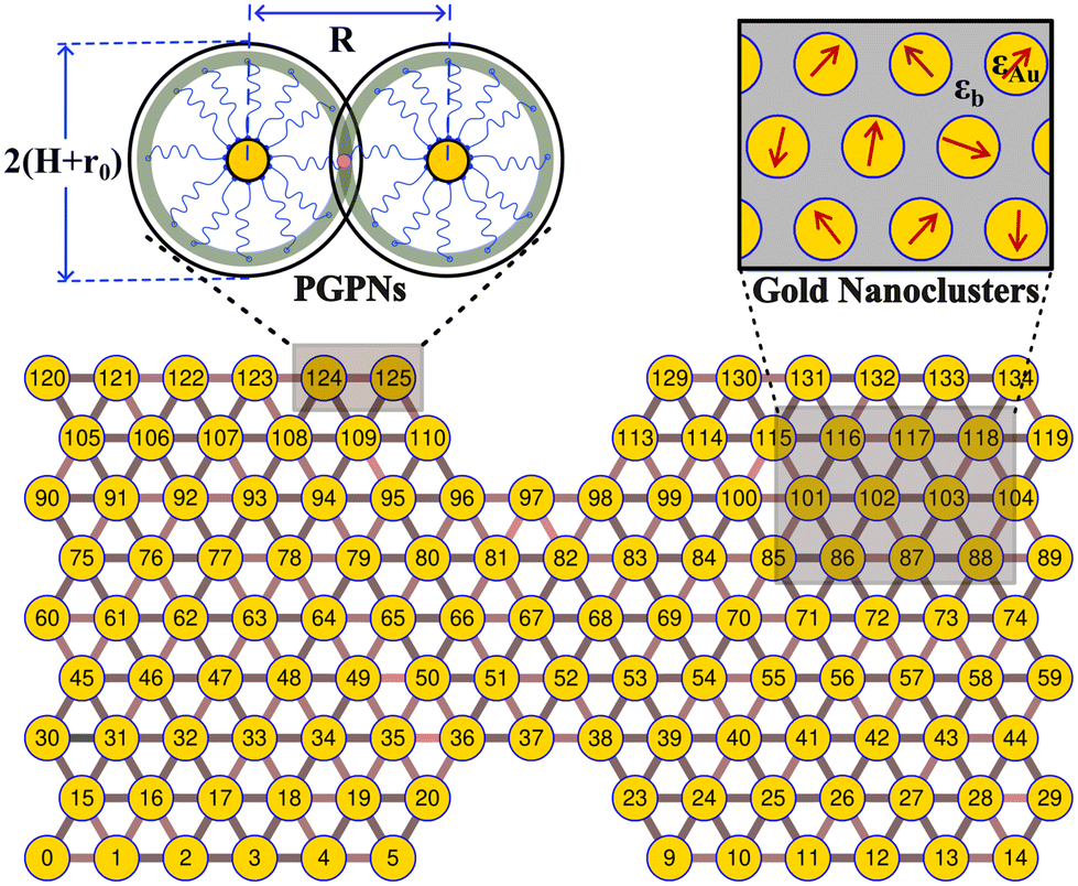
We consider a material system composed of identical polymer grafted plasmonic nanoparticles (PGPNs) with each particle having a spherical gold core of radius r0 = 25 nm and f = 900 polymers uniformly grafted on its surface. Each of the grafted arms are composed of 100 Kuhn monomers and are end-functionalized such that when they interact with neighboring PGPNs they form bonds of energy E = 39κBT in the zero force limit. The end-functionalised PGPNs are then cross-linked to form an extended monolayer thin film network (see Fig. 1) of different sizes. Two different numerical approaches for tracking (1) the mechanical and (2) plasmonic responses of PGPN networks were employed to investigate the relationship between the mechanical and plasmonic responses of arrays. Three different arrays composed of (1) 125, (2) 365 and (3) 925 PGPNs were investigated. The numerical approach for the mechanical response was based on the work of Phukan et al.43 while that of the plasmonic response was based on the work of Dutta-Gupta and Martin.44 The primary features associated with these numerical approaches are presented in sections 2.1–2.3.
 |
| | Fig. 1 The PGPNs are composed of gold nanoparticle cores with radius r0 = 25 nm and f = 900 polymers grafted on their surface. The pair interactions between the PGPNs help them to form a stable cross-linked network. Equilibrated double notched PGPNs arranged in a hexagonal lattice are stable and form gold nanoclusters with dipole moments that depend on the interaction between the PGPNs that form the array. | |
2.1 Pair particle interactions
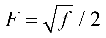
Pair interactions between the PGPNs were determined using the multi-component model developed by Sreedevi and Iyer.45 According to this model, the effective interactions between PGPNs have two parts arising from (1) non-bonded, Unb, and (2) bonded, Ub, interactions between the particles. The non-bonded potential is composed of repulsive (Urepnb(R)) and cohesive (Ucohnb(R)) interaction potentials, which are a function of centre-to-centre separation distance, R. The resulting non-bonded forces, Fnb = −∂Unb/∂R,A, between the PGPNs in the networks is given by:| |
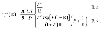 | (1) |
| |
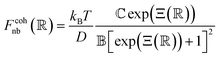 | (2) |
where,  is a parameter that depends on the number of grafted arms, f,
  is the scaled separation distance between the PGPNs, and D = 2(H + r0)/(1 + F−1) is the effective PGPN diameter.43 The location and range of the cohesive force are determined by the function,
 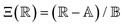 , where the dimensionless quantities
  and
and  are associated respectively with the location and width of the cohesive potential. The strength of the cohesive force is determined by the parameter
  .43 For the system with f = 900 grafted arms the values of A, B, and
  are provided in Table 1.
Table 1 Scaling factors and parameters used in the calculations
| Scaling factors |
| Length scale |
r 0 = 25 nm |
| Time scale |
T 0 = 7.04 × 10⁻³ s |
| Force scale |
F 0 = 1.03 pN |
| Energy scale |
E 0 = 6.25kBT at T = 300 K |
| Repulsion parameters |
D = 4.42r0 |
| Cohesion parameters |
A = 4.71r0, B = 0.2r0 and  |
| Chain parameters |
l p = 0.02r0 and L = 8r0 |
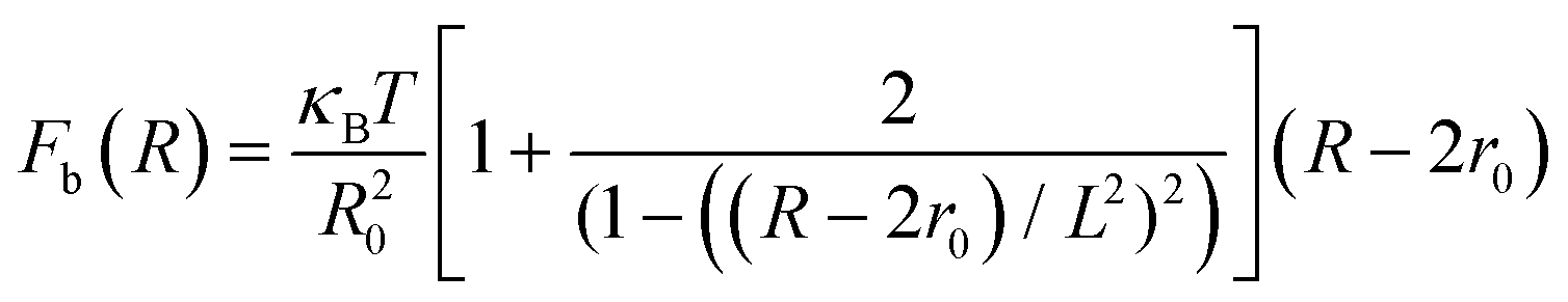
The total interactive potential due to the number of bonded polymer arms Nb between the PGPNs can be written as NbUb, and the corresponding total force is given by NbFb, where Fb = −∂Ub/∂R. When the polymer is considered as a worm-like chain, the force takes the form46
| |
 | (3) |
here, R − 2r0 gives the extent of the stretched arms of the cross-linked polymer, R20 = 2lpL is the ideal mean square polymer chain dimension, lp is the persistence length of the chain and L is the contour length of the cross-linked PGPN arm. The total interaction is obtained as a combination of these interactions: U = Unb + NbUb. The interactions are scaled using the scale factors listed in Table 1:
2.2 Equilibration and uniaxial elongation
In-house MPI parallel CUDA code was developed to investigate the equilibration and mechanical response of the equilibrated hexangonal array of PGPNS subjected to uniaxial elongation. Eight parallel simulations were performed to study the PGPN network of three different array sizes 9 × 15, 15 × 25 and 21 × 35. A notch of identical size was included in all the arrays for facilitating the study of the mechanical response of the networks. The total number of PGPN (np) present in each of these arrays is np: 125, np: 365 and np: 725, respectively. During equilibration, the PGPNs are not allowed to change their position in the lattice for about 60![[thin space (1/6-em)]](https://www.rsc.org/images/entities/char_2009.gif) 000T0 (where T0 is 7.04 × 10⁻³ s) in order to allow bond formation. Fluctuations in the evolution of the bonded interactions and the resulting many-body effects may lead to a small finite force on the hexagonal lattice even in the absence of three particle interactions. The average net force (x-component) on the right-edge PGPNs and the average net force (y-component) on the top-edge PGPNs were measured. The forces on the edges were then released linearly over 10000T0. The hexagonal lattice arrays were later equilibrated in the absence of force for about 50000T0. The equilibration protocol followed leads to the formation of stable hexagonal closed pack networks similar to those observed in our previous report.43
000T0 (where T0 is 7.04 × 10⁻³ s) in order to allow bond formation. Fluctuations in the evolution of the bonded interactions and the resulting many-body effects may lead to a small finite force on the hexagonal lattice even in the absence of three particle interactions. The average net force (x-component) on the right-edge PGPNs and the average net force (y-component) on the top-edge PGPNs were measured. The forces on the edges were then released linearly over 10000T0. The hexagonal lattice arrays were later equilibrated in the absence of force for about 50000T0. The equilibration protocol followed leads to the formation of stable hexagonal closed pack networks similar to those observed in our previous report.43
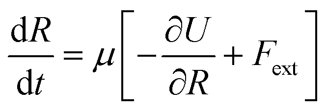
A uniaxial elongation was imposed on the notched PGPN arrays by pulling the right-edge at a constant velocity of 0.001u0 (see Fig. 3). The right edge acts like a clamp and is not allowed to deform during the simulation. The notches were introduced to facilitate particle arrangements in the array away from the edges and the resistance to deformation was measured at the right edge of the array. Eight parallel simulations were performed, like that in the equilibrium case, to determine the average forces on the right-edge and average strain-at-break. The imposed deformation causes the PGPN particles connected to the right edge of the array to rearrange their position. The evolution of this rearrangement was tracked considering that the dynamics of the PGPNs is in the overdamped regime because the individual PGPNs are small and can be considered as dispersed in a medium of high viscosity composed of similar PGPNs. The equation of motion of a single PGPN in this regime is written as:43
| |
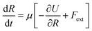 | (4) |
where
μ = 1/6π
η(
H +
r0) is the Stokes mobility of the PGPN, −∂
U/∂
R the net interactive force between two PGPNs and
Fext denotes the external force acting on the PGPN. The interactive force is dependent on the bonded interactions, which are a function of
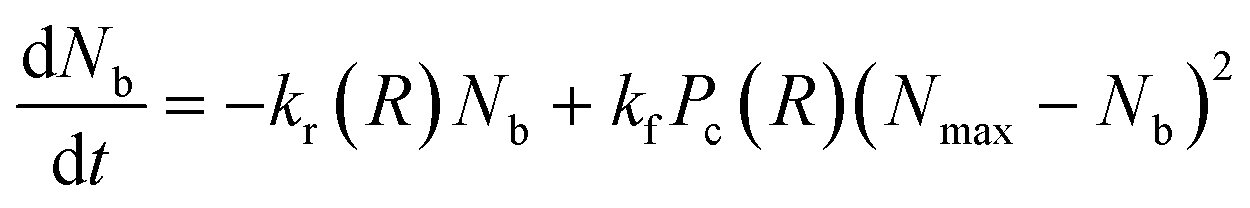
Nb. This requires that the equation of motion be solved along with the bond kinetics equation given by:
| |
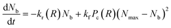 | (5) |
where
kr =
k0rexp(
γFb(
R)) is the force dependent bond rupture rate,
kf is the formation rate,
Pc(
R) is a measure of the availability of functional free ends for the formation of bonds in the overlap region between interacting PGNs and
Nmax is the measure of the maximum number of bonds that can be formed for a specific overlap.
45 In the present work, the equation of motion
(6) was numerically solved using the fourth-order Runge–Kutta method along with the bond evolution
eqn (7) using a protocol similar to that described in the studies of Phukan
et al.
43
2.3 Response of the plasmonic array
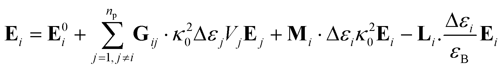
In the present work, each gold particle in the hexagonal lattice is considered to act as a dipole with an arbitrary orientation. The polymers grafted to the surface along with the background medium act as a polarizable background on which the plasmonic particles are embedded. For such a system, the electric field at the ith particle was calculated using the Green's tensor approach.44,47| |
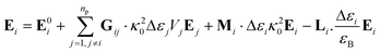 | (6) |
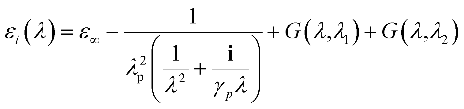
where the field at a particle depends on the incident field (E0i), Green's tensor (Gij), wavevector (κ0), volume of the particle (Vi), the permittivity of the particle (εi) and the permittivity of the background (εB). The permittivity of gold was taken from the analytic model presented by Etchegoin et al.48| |
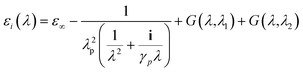 | (7) |
where, ε∞ = 1.54, plasma wavelength λp = 143 μm, damping γp = 14.5 μm, and G(λ1) and G(λ2) are contributions to the dielectric constant from interband transitions. Gold particles are known to have two interband transitions at wavelengths λ1 = 470 nm and λ2 = 325 nm and these contributions were calculated using the expression:| |
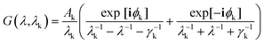 | (8) |
where k takes values 1 and 2 for the two wavelengths, ϕk = −π/4 and the values for transition broadening were taken as γ1 = 1900 nm and γ2 = 1060 nm.48 The permittivity of the background was fixed at 1.96. We assume that the background permittivity remains constant even when the network is deformed because density changes due to stretching in such PGPN networks are negligible. The total response of the system was computed by calculating and summing the responses of all the dipoles and their interactions were calculated using the field eqn (6) obtained from the Green's tensor approach. Subsequently, we evaluated the electric field outside the particles to extract the fields due to the nanoparticle array system. This was repeated at requisite strain values to understand the strain-dependent behaviour.
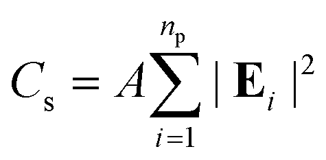
The optical response of the PGPN arrays of different sizes was studied using scattering analysis. The structure was illuminated with a z propagating plane wave with polarization along the x- or y-axis. The spectrum was calculated from the range 400 nm ≤ λi ≤ 700 nm and the normalized scattering crosssection was calculated. The scattering cross section (Cs) at a point in the far-field is given as:
| |
 | (9) |
where
np is the number of particles and
A is the area corresponding to the far point scattering surface. The total scattering cross section of the system at an incident condition is calculated by computing the electric field intensity at far-field points at a distance of 50 μm.
2.4 SERS response of PGPNs
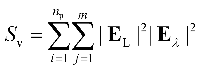
The surface-enhanced Raman scattering (SERS) response was calculated from the electric fields associated with the response to incident light at laser and Stokes wavelengths as follows:| |
 | (10) |
where, m is the number of observation points, EL is the electric field at the laser wavelength, and Eλ is the electric field at the Stokes wavelengths. The fields were evaluated at a distance of 2.5 nm from each of the nanoparticle surface. In the current study, we have fixed the laser wavelength to λL = 561 nm (where λL < λmax) and the Stokes lines were considered corresponding to the mercapto-benzoic acid (MBA) molecule.49 The wavelength for the two Stokes lines s1 and s2 were determined to be at 597 nm and 615 nm, respectively.
3 Results and discussion
3.1 Optical response of non-deformed PGPNs
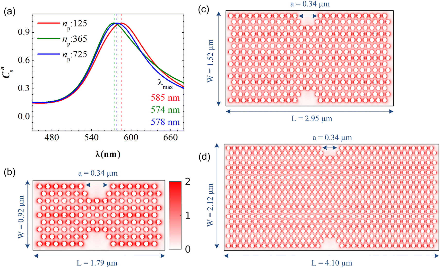
In the present work, the PGPNs were arranged to form a cross-linked network with a finite number of stable labile bonds with their neighbors in a hexagonal lattice at equilibrium (Fig. 1). Fig. 2(a) shows the far-field scattering spectrum of the arrays of different sizes when illuminated with a normally incident X-polarized plane wave. It is evident that all the three PGPNs exhibit a strong resonance close to 580 nm. The resonance wavelengths for the arrays composed of 125, 365 and 725 PGPNs are at 585 nm, 574 nm and 578 nm, respectively. Fig. 2(b)–(d) show the electric field amplitude on an xy-plane at z = 0 nm for the three cases at resonance. It should be noted that for polarized illumination, the maximum near-field is observed along the direction of polarization (see Fig. (S1–S3)†). The near-field maps clearly indicate the plasmonic nature of the resonance, with the enhancements being the maximum around the particles and oriented along the x-direction. Furthermore, particles in some of the rows of PGPNs exhibit higher field enhancement as compared to the other rows. This is due to the mutual interaction between particles and those particle positions that undergo constructive interference, thereby exhibiting higher field enhancements.
 |
| | Fig. 2 (a) Normalized scattering cross section, Cns, as a function of wavelength for three PGPN arrays composed of 125 (red curve), 365 (green curve) and 725 (blue curve) PGPNs. Electric field amplitude on the xy-plane (where z = 0) for the arrays with (b) 125, (c) 365 and (d) 725 PGPNs. The structure is illuminated with an X-polarized plane wave propagating in the z direction. The electric field maps are calculated at the resonance wavelengths, λmax. | |
3.2 Mechanical deformation of PGPNs
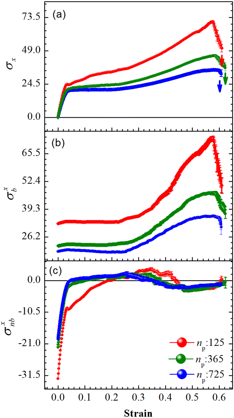
An array subject to uniaxial elongation resists deformation and the PGPNs in the array rearrange their positions (see Fig. 3). Due to this the mechanical and plasmonic responses of the PGPN network evolve as a function of elongation strain. The force of resistance in the direction of deformation depends on both the strain and the size of the array. The dimensionless stress in the network can be considered as the ratio of the force of resistance to the thickness of the sample, ax = Fx/W (Fig. 4(a)). The force and thickness are both scaled with reference to the scaling units given in Table 1 to obtain the dimensionless stress. The evolution of this stress response in PGPN networks is seen to have two parts: (1) the initial small strain response where the non-bonded interactions dominate (Fig. 4(c)) and (2) the large strain response where for strains of α > 0.3 the bonded interactions dominate (Fig. 4(b)). In this, we note that both bonded and non-bonded contributions tend to become independent of size beyond a critical size. Furthermore, we note that the bonded forces do not change significantly with strain in the region 0 < α < 0.3. In contrast, the non-bonded forces change sharply in a small window of strain 0 < α < 0.05. This leads to a region of strain, 0.05 < α < 0.3, where the force required to deform does not change significantly leading to a yield like response. Based on this response we expect the onset of particle rearrangements in this regime followed by enhanced particle rearrangements at strains of α > 0.3.
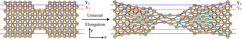 |
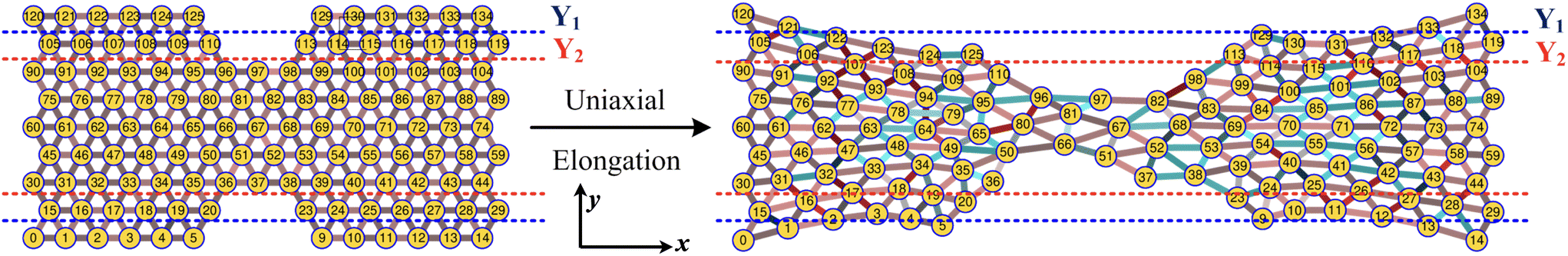
| | Fig. 3 Schematic of the uniaxial elongation of the PGPN array at a constant pulling velocity u = 0.001u0 in the x direction. The snapshot of the deformed array is provided at an elongational strain of α = 0.6. The horizontal dashed blue and red lines demarcate the regions Y1 and Y2, which are normal to the direction of elongation (y direction), respectively. The number of PGPNs within the demarcated regions evolves with strain. | |
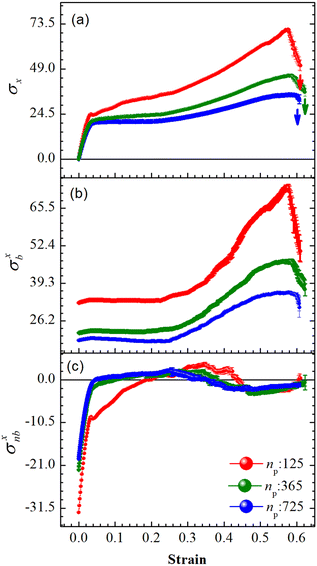 |
| | Fig. 4 Average forces per unit thickness, σ = F/W, on the right edge of the PGPN arrays along the direction of stretching as a function of strain at constant pulling velocity, u = 0.001u0, and E = 39kBT. (a) The net force, σx: Fx/W, (b) bonded contributions, σxb: Fb/W and (c) non-bonded contributions, σxnb: (Frepnb + Fcohnb)/W. | |
3.3 Mechano-optical coupling: fixed region
While the forces are measured on the right edge of the array, the particle arrangements inside the array depend on the interaction of the PGPNs with their neighbours. To track these rearrangements we can either mark particles and track the evolution of the position of these particles or define regions and track the migration of particles into and out of these regions due to the imposed deformation. Such rearrangements are expected to lead to the modification of the dipole orientation of the individual PGPNs as these orientations are expected to depend on both the incident field and the interaction of the PGPN with its neighbors. Note that each strain value corresponds to a set of different particle positions and this is taken into consideration for the field calculation. Subsequently, the variation of the surface enhanced Raman scattering is calculated using eqn (10).
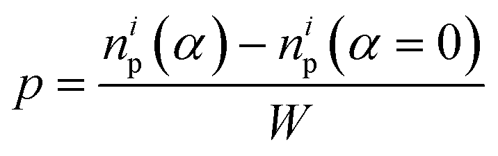
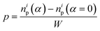
First, we focus on the case of tracking migration of particles into/out of the regions marked by Y1 and Y2 and the associated plasmonic response (see Fig. 3). It was observed that the imposed deformation caused the number of particles in the regions to increase due to the migration of the PGPNs into this region. The extent of this migration was characterized by the packing parameter defined as:
| |
 | (11) |
where
np is the number of particles in the region at a specified strain,
α, and
i = 1, 2 yields the packing in the regions
Y1 and
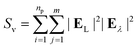
Y2, respectively. Here, the increase in the number of PGPNs in the regions from the equilibrium value is normalized by the width of the sample to account for the differences in the sample size. The relative SERS enhancement due to the migration of particles was tracked by the evolution of the parameter:
| |
 | (12) |
where
Sν (
α) is the SERS enhancement calculated at a specific strain,
α, using
eqn (10).
The evolution of the packing parameter in the region Y1, in our simulations, indicates that the onset of packing depends on the size of the sample with a tendency to have an earlier onset in samples of larger size. However, the saturation values of the packing parameter in the region are relatively independent of the size of the sample. A distinction may be seen between small and the two large samples in terms of the nature of this evolution. The former shows a sharp increase in the packing, followed by a plateau and decay at large strain (see Fig. 5(a)). On the other hand, the larger samples tend to pack relatively slowly to reach the maximum packing value (see Fig. 5(b) and (c)). In particular, the packing parameter, p, increases from 0 to 0.96 due to deformation. The maximum value of 0.96 is reached over a short range of strains between 0.3 and 0.5 in the small array. The increase in the value of the parameter is sharp compared to that of larger arrays. This increase is followed by a plateau at 0.96 at strains greater than 0.5 and falls to a lower value of p in the region of strain close to α = 0.6. This drop may be due to elastic recoiling in certain parts of the small array that leads to PGPNs moving away from the Y1 region. In contrast, the packing parameter gradually increases from a value of 0 to 0.96 over a strain range of 0.1–0.5 with the increase in p slowing down significantly at strains greater than 0.4.
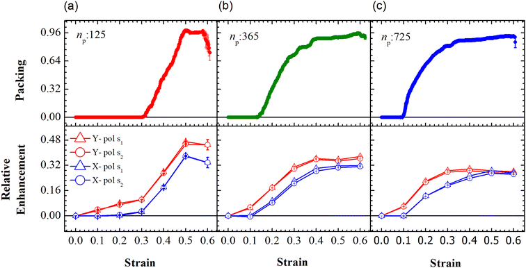 |
| | Fig. 5 Evolution of packing and relative enhancement as a function of strain, α, at u = 0.001u0 and E = 39kBT within the demarcated region, Y1 (See Fig. 3). Plots showing packing, p = (n1p(α) − n1p (α = 0))/W, for the arrays composed of (a) 125, (b) 365 and (c) 725 PGPNs, where n1p is the number of PGPN units in the region Y1. The corresponding relative enhancement plots for the three arrays are respectively shown below, calculated as (Sν(α) − Sν(α = 0))/Sν(α = 0). The enhancements are evaluated for both X (blue) and Y (red) polarizations, and at two Stokes lines, s1 (triangle) and s2 (circle), corresponding to the mercapto-benzoic acid (MBA) molecule.49 | |
The relative SERS enhancement in this region closely follows the trends shown by the packing parameter. Specifically, the enhancement corresponding to the Stokes wavelengths of λ = 597 nm and λ = 615 nm varies sharply around the onset of packing. However, differences in the evolution of the relative SERS enhancement indicate that the response corresponding to the Y-polarization is more sensitive to the variation of the PGPN position with strain. The particles tend to migrate in a direction normal to that of the deformation. This leads to packing of the particles as shown in Fig. 5 and 6. The packing happens in the y-direction which is the direction normal to that of the deformation. Packing leads to stronger near-field coupling and near-field enhancement for Y-polarization. Unlike the evolution of packing in region Y1, the region Y2 has no clear saturation and the evolution is continuous with minor shoulders at intermediate strains (see Fig. 6). Furthermore, the maximum packing values increase with the size of the network. The evolution of relative enhancement in this region also follows the packing patterns with both shoulders and the continuous evolution with the increase in strain values. The resonance wavelength of the PGPNs does not significantly change due to deformation or due to the number of particles in the PGPNs.50 This is due to the relatively large gaps (around 60 nm) between neighboring particles, leading to weak near-field coupling between the particles. However, we show that the interaction with the neighboring particles can lead to modifications in the relative enhancements, depending on the polarization direction of the incident light, as shown in Fig. 5 and 6. This may be a consequence of our calculation of only dipole modes in Au nanoparticles. We also observe that the relative enhancement and the packing roughly follow the same trend, mainly due to strong LSPR coupling when the particle–polymer networks are closely packed. We note that all these results are independent of the choice of the wavelengths s1 and s2.
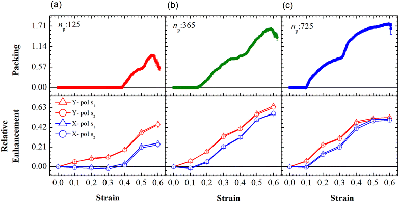 |
| | Fig. 6 Evolution of packing and relative enhancement as a function of strain, α, at u = 0.001u0 and E = 39kBT within the demarcated region, Y2 (See Fig. 3). Plots showing packing, p = (n2p(α) − n2p(α = 0))/W, for the arrays composed of (a) 125, (b) 365 and (c) 725 PGPNs, where n2p is the number of PGPN units in the region Y2. The corresponding relative enhancement plots for the three arrays are respectively shown below, calculated as (Sν(α) − Sν(α = 0))/Sν(α = 0). The enhancements are evaluated for both X (blue) and Y (red) polarizations, and at two Stokes lines, s1 (triangle) and s2 (circle), corresponding to the mercapto-benzoic acid (MBA) molecule.49 | |
3.4 Mechano-optical coupling: fixed particle tracking
Particle rearrangement can also be tracked for labeled particles in a region (see Fig. 7(a)). Here, the number of labeled PGPNs is fixed for a given network while the region over which these particles move evolves due to imposed deformation. In the case of a small array, with np = 125 particles, 45 PGPNs are labeled (see Fig. 7(a)). In the case of large arrays, with np = 365 and 725, 165 and 357 PGPNs in the region between the notches are labeled. The evolution of the positions of the labeled PGPNs, as the network is deformed, indicates that both packing in the direction normal to that of the deformation and sliding in the direction of deformation can lead to changes in the relative positions between the particles (see Fig. 7(a)). The corresponding effect on the relative enhancement measured by calculating the SERS enhancement due to the labeled particles is qualitatively different from that discussed earlier for the regions Y1 and Y2. In particular, the relative enhancement due to the labeled PGPNs depends both on the polarization of the incident laser and the size of the network. For small networks, with np = 125 PGPNs, we observe that the relative enhancement evolves with strain to become negative or positive depending on the polarization (see Fig. 7(b)). In contrast, the enhancement remains positive at large strains with non-monotonic responses for both polarizations in the larger networks with np = 365 and 725 PGPNs. The results indicate that an interplay of both packing and sliding, in the rearrangement of the labeled PGPNs, determines the evolution of the relative enhancement with strain.
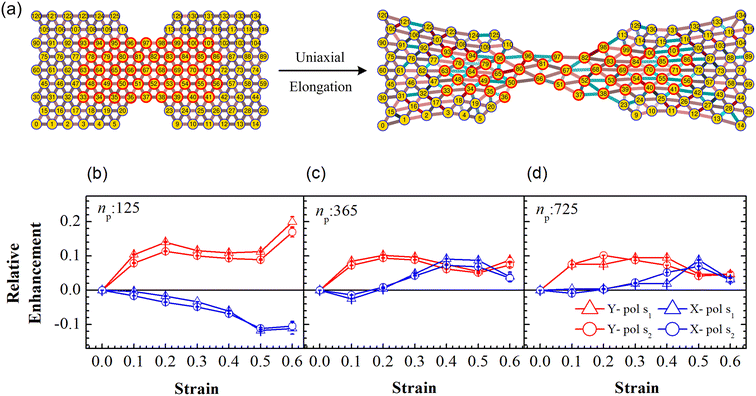 |
| | Fig. 7 (a) Schematic of uniaxial elongation of the PGPN array at a constant pulling velocity u = 0.001u0. Relative enhancement is analyzed for the PGPN units marked in a red circle. Relative enhancement plots for the arrays composed of (b) 125, (c) 365 and (d) 725 PGPNs, calculated as (Sν(α) − Sν(α = 0))/Sν(α = 0). The responses are evaluated for both X (blue) and Y (red) polarizations, and at two Stokes lines s1 (triangle) and s2 (circle), corresponding to the mercapto-benzoic acid (MBA) molecule.49 | |
Localized surface plasmon resonances exhibit enhanced near-field amplitude and are highly localized in the vicinity of the nanoparticle. The electric field enhancement at resonance decays rapidly away from the nanoparticle–dielectric interface into the dielectric background.51,52 Note that typically smaller gaps along the direction of incident polarization lead to an increase in the electric field enhancement in the gaps due to the near-field coupling of the neighbouring particles. In Fig. 7(b), the relative enhancement seems to decrease (negative enhancement) when the system is X polarized as the separation distance of the particles increases along the x direction (see Fig. 7(a)). For larger networks with np = 365 and 725 PGPNs, we observe negative enhancement when α = 0.1, which further increases (positive enhancement) when central particles rearrange along the x direction with an increase in strain. Meanwhile the positive enhancement in the Y − polarization is observed mainly due to a decrease in the separation distance of the particles along the y direction due to packing. From our analysis, we observe that hexagonally arranged PGPN networks enhance SERS when they pack irrespective of whether we observe a specific region or track a fixed set of particles. On the other hand, stretching induced separation of particles along the direction of elongation causes reduction in enhancement. Thus, the evolution of the spatial organization of the hexagonal PGPN network is coupled to the evolution of the SERS enhancement. Here, the overall surface enhancement is decided by the interplay between the packing and sliding of the particles at different strains.
To understand the interplay between packing and sliding it is useful to look at the new results in the light of the packing results for the region Y2 since all the labeled PGPNs lie in this region. We have already shown that packing evolves continuously in the Y2 region and consequently leads to increase in the relative enhancement. The influx of particles into the Y2 region can cause the labeled particles to come close to each other or slide away in the direction of deformation. The relative enhancement due to the labeled particles is thus expected to increase or decrease depending on which of these effects dominate. In the small array, for strains α < 0.4, there is no influx of particles into the Y2 region and the rearrangements are driven only by the interaction between labeled particles. Here, the packing in the normal direction leads to an increase in enhancement for the Y polarization and sliding leads to reduction in X polarization. In the case of larger arrays, the early onset of particle migration leads to considerable influx of particles in the Y2 region, so the labeled particles may either pack together or slide away leading to a mixed response. This mixed response results in mild enhancements for Y polarization and a mild drop or increase in relative enhancement for X polarization depending on the strain. Specifically, at small strains the tendency to pack is stronger and leads to an enhancement of the Y-polarization response. On the other hand, at larger strains the relative rearrangements of the labeled PGPNs are such that the response reaches a saturation value and remains relatively unaffected by strain. We also note that the shoulders in packing (see Fig. 6) correspond to transitions that lead to a crossover of the relative enhancement due to X and Y polarizations (see Fig. 7(b–d)). We note that all these results are independent of the choice of the wavelengths s1 and s2.
4 Conclusions
The dynamic evolution of the localised surface plasmon response (LSPR) of an array of polymer grafted gold nanoparticles (PGPNs) of 25 nm radius was studied using multiscale simulations and the Green's tensor approach. We demonstrated using simulations and field calculations that the LSPR evolves depending on the rearrangement of the particles and the size of the array. Two different approaches were used to investigate the LSPR of arrays of different sizes. In the first approach, regions of fixed width were identified and the evolution of particle rearrangements and SERS enhancement was studied in this region. In the second approach a set of PGPNs were identified and the resulting enhancement due to these particles was studied for incident light of different polarizations.
In the first approach the field enhancement in the fixed region was shown to closely mimic the evolution of the packing of particles as the array was deformed. Furthermore, the evolution of enhancement was observed to be similar irrespective of the polarization of the incident light. In contrast, the SERS enhancement associated with a fixed number of PGPNs strongly depended on the polarization of the incident light. The results indicated that tracking SERS enhancement in a region of fixed width and for fixed particles provides insights into two qualitatively different aspects of the evolution of the structure of the deformed array. The former was sensitive to overall packing, while the latter was sensitive to local rearrangements of the particles in the array. We have thus established that the evolution of SERS enhancement when an array of PGPNs is deformed is a useful tool for studying large scale and local structural rearrangements.
Author contributions
The problem was conceptualized and the methodology developed by BI and SDG. The funding was acquired by BI. The simulation and analysis were performed by TRR. The work was supervised by BI and SDG. The manuscript was written by TRR. The manuscript was reviewed and edited by BI and SDG.
Conflicts of interest
There are no conflicts to declare.
Note added after first publication
This article replaces the version published on 11th June 2024 where the symbol ![[Doublestruck R]](https://www.rsc.org/images/entities/char_e175.gif) was missing from eqn 1 and 2 and the corresponding text where the equations were discussed.
was missing from eqn 1 and 2 and the corresponding text where the equations were discussed.
Acknowledgements
BI and TRR acknowledge funding from National Supercomputing Mission grant DST/NSM/R&D_HPC_Applications/2021/01. SDG acknowledges the funding from IIT Hyderabad grant IITH/BME/F110/SOCH4.
References
- S. K. Kumar, B. C. Benicewicz, R. A. Vaia and K. I. Winey, Macromolecules, 2017, 50, 714–731 CrossRef CAS.
- W.-L. Chen, R. Cordero, H. Tran and C. K. Ober, Macromolecules, 2017, 50, 4089–4113 CrossRef CAS.
- W. R. Lenart and M. J. Hore, Nano-Struct. Nano-Objects, 2018, 16, 428–440 CrossRef CAS.
- H. Shimamoto, C.-H. Cheng, K. Kamitani, K. Kojio, Y. Higaki and A. Takahara, Macromolecules, 2019, 52, 5963–5970 CrossRef CAS.
- M. J. A. Hore, L. T. J. Korley and S. K. Kumar, J. Appl. Phys., 2020, 128, 030401 CrossRef CAS.
- C. Yi, Y. Yang, B. Liu, J. He and Z. Nie, Chem. Soc. Rev., 2020, 49, 465–508 RSC.
- J. O. Zoppe, N. C. Ataman, P. Mocny, J. Wang, J. Moraes and H.-A. Klok, Chem. Rev., 2017, 117, 1105–1318 CrossRef CAS PubMed.
- M. Asai, D. Zhao and S. K. Kumar, ACS Nano, 2017, 11, 7028–7035 CrossRef CAS PubMed.
- L. Michalek, L. Barner and C. Barner-Kowollik, Adv. Mater., 2018, 30, 1706321 CrossRef PubMed.
- A. J. Chancellor, B. T. Seymour and B. Zhao, Anal. Chem., 2019, 91, 6391–6402 CrossRef CAS PubMed.
- J. Yan, M. R. Bockstaller and K. Matyjaszewski, Prog. Polym. Sci., 2020, 100, 101180 CrossRef CAS.
- G. A. Williams, R. Ishige, O. R. Cromwell, J. Chung, A. Takahara and Z. Guan, Adv. Mater., 2015, 27, 3934–3941 CrossRef CAS PubMed.
- G. Hou, X. Xia, J. Liu, W. Wang, M. Dong and L. Zhang, J. Phys. Chem. B, 2019, 123, 2157–2168 CrossRef CAS PubMed.
- H. Yun, J. W. Yu, Y. J. Lee, J.-S. Kim, C. H. Park, C. Nam, J. Han, T.-Y. Heo, S.-H. Choi, D. C. Lee, W. B. Lee, G. E. Stein and B. J. Kim, Chem. Mater., 2019, 31, 5264–5273 CrossRef CAS.
- B. Wetzel, F. Haupert and M. Q. Zhang, Compos. Sci. Technol., 2003, 63, 2055–2067 CrossRef CAS.
- H. Zhang, Z. Zhang, K. Friedrich and C. Eger, Acta Mater., 2006, 54, 1833–1842 CrossRef CAS.
- X. Zhao, Q. Zhang, D. Chen and P. Lu, Macromolecules, 2010, 43, 2357–2363 CrossRef CAS.
- M. Giovino, J. Pribyl, B. Benicewicz, R. Bucinell and L. Schadler, Nanocomposites, 2018, 4, 244–252 CrossRef.
- S. Nie and S. R. Emory, science, 1997, 275, 1102–1106 CrossRef CAS PubMed.
- K. Kneipp, Y. Wang, H. Kneipp, L. T. Perelman, I. Itzkan, R. R. Dasari and M. S. Feld, Phys. Rev. Lett., 1997, 78, 1667–1670 CrossRef CAS.
- E. C. Le Ru, J. Grand, I. Sow, W. R. C. Somerville, P. G. Etchegoin, M. Treguer-Delapierre, G. Charron, N. Félidj, G. Lévi and J. Aubard, Nano Lett., 2011, 11, 5013–5019 CrossRef CAS PubMed.
- P. Bandaru, S. Bhattacharyya and S. Dutta-Gupta, J. Appl. Phys., 2022, 132, 183101 CrossRef CAS.
- E. Mukherjee, J. Pillanagrovi, D. Bhatnagar and S. Dutta-Gupta, J. Appl. Phys., 2023, 133, 073101 CrossRef CAS.
- J. Lee, B. Hua, S. Park, M. Ha, Y. Lee, Z. Fan and H. Ko, Nanoscale, 2014, 6, 616–623 RSC.
- U. Kreibig and M. Vollmer, Optical properties of metal clusters, Springer Science & Business Media, 2013, vol. 25 Search PubMed.
- K. L. Kelly, E. Coronado, L. L. Zhao and G. C. Schatz, J. Phys. Chem. B, 2003, 107, 668–677 CrossRef CAS.
- P. Bandaru, G. Ummethala, S. R. K. Malladi and S. Dutta-Gupta, J. Phys. Chem. C, 2022, 126, 15915–15923 CrossRef CAS.
- Y. Liu and Y. Ma, Front. Phys., 2020, 8, 312 CrossRef.
- J.-M. Kim, C. Lee, Y. Lee, J. Lee, S.-J. Park, S. Park and J.-M. Nam, Adv. Mater., 2021, 33, 2006966 CrossRef CAS PubMed.
- G. Kelp, J. Li, J. Lu, N. DiNapoli, R. Delgado, C. Liu, D. Fan, S. Dutta-Gupta and G. Shvets, Lab Chip, 2020, 20, 2136–2153 RSC.
- M. Bahramipanah, S. Dutta-Gupta, B. Abasahl and O. J. F. Martin, ACS Nano, 2015, 9, 7621–7633 CrossRef CAS PubMed.
- H. Duan, Y. Yang, Y. Zhang, C. Yi, Z. Nie and J. He, Giant, 2020, 4, 100033 CrossRef.
- P. Barman, A. Chakraborty, D. A. Akimov, A. K. Singh, T. Meyer-Zedler, X. Wu, C. Ronning, M. Schmitt, J. Popp and J.-S. Huang, Nano Lett., 2022, 22, 9914–9919 CrossRef CAS PubMed.
- J. Butet, S. Dutta-Gupta and O. J. F. Martin, Phys. Rev. B: Condens. Matter Mater. Phys., 2014, 89, 245449 CrossRef.
- Y. Dong, C. Hu, H. Xiong, R. Long and Y. Xiong, ACS Catal., 2023, 13, 6730–6743 CrossRef CAS.
- Z. Fan, S. Dutta-Gupta, R. Gladstone, S. Trendafilov, M. Bosch, M. Jung, G. R. S. Iyer, A. J. Giles, M. Shcherbakov, B. Feigelson, J. D. Caldwell, M. Allen, J. Allen and G. Shvets, Nanophotonics, 2019, 8, 1417–1431 CrossRef CAS.
- N. Dabidian, S. Dutta-Gupta, I. Kholmanov, K. Lai, F. Lu, J. Lee, M. Jin, S. Trendafilov, A. Khanikaev, B. Fallahazad, E. Tutuc, M. A. Belkin and G. Shvets, Nano Lett., 2016, 16, 3607–3615 CrossRef CAS PubMed.
- S. H. S. Mandala, T.-J. Liu, C.-M. Chen, K.-K. Liu, M. Januar, Y.-F. Chang, C.-S. Lai, K.-H. Chang and K.-C. Liu, Biosensors, 2021, 11, 402 CrossRef CAS PubMed.
- A. N. Koya, J. Cunha, K. A. Guerrero-Becerra, D. Garoli, T. Wang, S. Juodkazis and R. Proietti Zaccaria, Adv. Funct. Mater., 2021, 31, 2103706 CrossRef CAS.
- L. Polavarapu and L. M. Liz-Marzán, Phys. Chem. Chem. Phys., 2013, 15, 5288–5300 RSC.
- D. Shir, Z. S. Ballard and A. Ozcan, IEEE J. Sel. Top. Quantum Electron., 2016, 22, 12–20 Search PubMed.
- Y. Chuo, D. Hohertz, C. Landrock, B. Omrane, K. L. Kavanagh and B. Kaminska, IEEE Sens. J., 2013, 13, 3982–3990 Search PubMed.
- M. Phukan, P. Haritha, T. R. Roy and B. V. S. Iyer, Soft Matter, 2022, 18, 8591–8604 RSC.
- S. Dutta-Gupta and O. J. F. Martin, J. Opt. Soc. Am. B, 2015, 32, 194–200 CrossRef CAS.
- A. M. Sreedevi and B. V. S. Iyer, Ind. Eng. Chem. Res., 2019, 58, 7478–7488 CrossRef CAS.
- A. V. Dobrynin and J.-M. Y. Carrillo, Macromolecules, 2011, 44, 140–146 CrossRef CAS.
- O. J. F. Martin and N. B. Piller, Phys. Rev. E: Stat., Nonlinear, Soft Matter Phys., 1998, 58, 3909–3915 CrossRef CAS.
- P. G. Etchegoin, E. C. Le Ru and M. Meyer, J. Chem. Phys., 2006, 125, 164705 CrossRef CAS PubMed.
- L. Jiang, T. You, P. Yin, Y. Shang, D. Zhang, L. Guo and S. Yang, Nanoscale, 2013, 5, 2784–2789 RSC.
- H. Yu, P. Zhang, S. Lu, S. Yang, F. Peng, W.-S. Chang and K. Liu, J. Phys. Chem. Lett., 2020, 11, 5836–5843 CrossRef CAS PubMed.
- J. B. González-Díaz, A. García-Martín, J. M. García-Martín, A. Cebollada, G. Armelles, B. Sepúlveda, Y. Alaverdyan and M. Käll, Small, 2008, 4, 202–205 CrossRef PubMed.
- G. X. Du, T. Mori, M. Suzuki, S. Saito, H. Fukuda and M. Takahashi, Appl. Phys. Lett., 2010, 96, 081915 CrossRef.
|
| This journal is © The Royal Society of Chemistry 2024 |
Click here to see how this site uses Cookies. View our privacy policy here. 
 *a
*a

 is a parameter that depends on the number of grafted arms, f,
 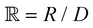 is the scaled separation distance between the PGPNs, and D = 2(H + r0)/(1 + F−1) is the effective PGPN diameter.43 The location and range of the cohesive force are determined by the function,
  , where the dimensionless quantities
  and
and  are associated respectively with the location and width of the cohesive potential. The strength of the cohesive force is determined by the parameter
  .43 For the system with f = 900 grafted arms the values of A, B, and
  are provided in Table 1.