
 Open Access Article
 This Open Access Article is licensed under a Creative Commons Attribution-Non Commercial 3.0 Unported Licence
Cobalt–iron layered double hydroxide nanosheet-wrapped nitrogen-doped graphite felt as an oxygen-evolving electrode
Noor Fatima
Shahid
a,
Ahsan
Jamal
a,
Gulfam-ul
Haq
a,
Maham
Javed
a,
Muhammad
Saifullah
b and
Mohsin Ali Raza
Anjum
 *a
*a
aRenewable Energy Group, Chemistry Division, Directorate of Science, Pakistan Institute of Nuclear Science and Technology (PINSTECH), P.O. Nilore, Islamabad, 45650, Pakistan. E-mail: mohsinpieas@hotmail.com
bChemistry Division, Directorate of Science, Pakistan Institute of Nuclear Science and Technology (PINSTECH), P.O. Nilore, Islamabad, 45650, Pakistan
First published on 7th November 2023
Abstract
The electrocatalytic performance of cobalt–iron layered double hydroxide (CoFe-LDH) nanosheets is enhanced by growing them in situ on N-doped graphite felt using a solvothermal route. The effects of different parameters including solvent, temperature and reaction time are investigated. Pure CoFe-LDH nanosheets are obtained using methanol as a solvent at the optimum temperature (130 °C) and reaction time (18 hours) while metal (Fe and Co) oxides are formed in a hydrothermal process. The CoFe-LDH@NGF (130 °C, 18 h) displays enhanced catalytic performance and stability for the oxygen evolution reaction (OER) in alkaline media and produces a current density of 10 mA cm−2 at a low overpotential (220 mV), Tafel slope of 121 mV dec−1, charge transfer resistance of 1.48 Ω, high exchange current density and double layer capacitance of 226.65 mF cm−2. The OER activity of the CoFe-LDH@NGF electrode exceeds that of pristine CoFe-LDH, conventional RuO2, and other CoFe-LDH-based electrocatalysts reported in the literature. Thus, the CoFe-LDH@NGF electrode is a potential alternative to expensive noble metals (Ru, Ir) and other transition metal-based electrocatalysts for commercial alkaline water splitting. Moreover, the current synthesis approach can be employed to make other layered double hydroxide-based electrodes for electrochemical applications.
Introduction
Conventional fossil fuels like coal, oil and natural gas are being extensively consumed to meet the global energy demand and for hydrogen production, which is causing a serious threat to environment because of greenhouse gas emissions.1 Therefore, scientists and researchers have devoted their efforts to finding alternative clean, and cost-effective energy resources to minimize the dependence on fossil fuels.2 Because of its high energy density with zero carbon emissions, hydrogen is considered a potential source of energy to replace fossil fuels.2,3 The electrochemical water splitting is sustainable and promising method to produce hydrogen at commercial scale.4,5 It has many advantages over conventional high-pressure and high-temperature steam methane reforming and coal gasification; highly pure hydrogen gas can be produced at ambient conditions with less energy loss.6,7 Two types of reactions are involved in water electrolysis: the hydrogen evolution reaction (HER) occurs at the cathode and the oxygen evolution reaction (OER) proceeds at anode.8,9 The OER is very sluggish and follows a complex four-electron transfer mechanism, hence it requires a large overpotential as compared to the theoretical value, i.e., 1.23 V.10 Electrocatalysts play an important role in reducing the overpotential; traditionally, noble metals (Ru, Ir and Pt) are considered the best electrocatalysts for overall water splitting. However, low earth abundance, high cost, and poor operational stability hinder their commercial applications.11,12 Therefore, economical, highly stable and efficient electrocatalysts are needed to promote this technology at large scale. Currently, the most promising alternatives for OER electrocatalysts are transition metal-based (e.g. Co, Fe, Ni, Mo and Mn etc.) compounds including metal oxides,13 phosphides,14 LDH,15,16 selenides,13 hydroxides,17 sulfides18 and nitrides.19 Particularly, layered double hydroxides (LDHs) have been extensively studied as electrocatalysts for water splitting because of their green synthesis process, highly tunable nature for chemical, electrochemical and electronic properties, and more widely available less expensive synthetic precursors than the traditional noble metals.20LDHs have an ion lamellar-type crystal structure that primarily consists of three components: positively charged brucite-like host upper and lower metal hydroxide layers [M2+1−xMx3+(OH)2]x+, also called the basal plane, interlayer anions (to balance charge) and solvent molecules.21,22 Their molecular formula can be expressed as [M1−x2+Mx3+(OH)2][An−]x/n·zH2O, where M2+ represents a divalent metal cation (e.g., Ni2+, Fe2+ and Co2+), and M3+ denotes a trivalent metal cation (e.g. Al3+, Fe3+, Ga3+ or Mn3+), An− stands for an intercalant anion (e.g. NO3−, Cl−, SO42−, RCO2−, and CO32−) and x ranges from 0.2 to 0.4.23–25 In LDH, the cation layer (basal plane) is sandwiched between two hydroxide layers; these two brucite-like layers are intercalated by replaceable anions and/or water molecules, which act as ball bearings to slide, separate and enhance the interlayer space, and hence electrolyte can easily be moved between the cation and hydroxide layers.26,27 Owing to these special features, the electrocatalytic properties of LDH can be tuned by changing the intercalant anion size, doping heteroatoms, optimizing the cationic ratio (M2+/M3+), or increasing the electrochemical surface area through nano-structure engineering and growing on conductive support.28
LDH with various combinations of divalent and trivalent cations of 3d transition metals such as Ni–Fe,29 Ni–Co,30 Co–Ni,31 Co–Mn32 and Co–Co,33 have been investigated for water splitting. Co-based hydroxide is thought to be a potential electrocatalyst for OER and its performance increases significantly after incorporation of Fe3+ cations into its solid solution compared to pristine Co-LDHs.34 The Fe species in CoFe-LDH helps in forming more oxo species (O˙ radicals) at low overpotential, which are required for the OER, additionally. The Co-LDH also provides a conductive support to the most active site of Fe3+, thus the OER performance is enhanced by the synergistic effect between both Co and Fe species.35 The stability and electrical conductivity of the catalyst support/substrate play very important roles in electrocatalysis, so metal-based (Ni, Cu etc.) foams and foils,36–39 and carbon-based supports (graphene, nanotubes, carbon cloth, carbon paper, graphite felt)40–43 are used. Although the metal foams provide excellent conductivity and high surface area, their high cost, electrochemical/chemical instability, especially in acidic media, low elasticity and poor flexibility hinder their use in commercial applications.44 Moreover, the metallic foams become more fragile during high-temperature sample fabrication; they decompose, react with catalysts and change their chemical composition.18 Graphite felt (GF), a carbon-based substrate, is considered a better alternative due to its high electrical conductivity close to that of metal (370.37 S m−1), high volumetric porosity (ε < 0.98), good mechanical integrity and low cost.45,46 Its electrical conductivity can further be improved by doping heteroatoms (N, O, S, P, etc.). To the best of our knowledge, only a few studies have been conducted on GF.
Here, we report self-supported CoFe-LDH nanosheets grown in situ on nitrogen-doped GF (CoFe-LDH@NGF) as an efficient oxygen-evolving electrode in alkaline media. The effect of synthetic parameters on the preparation of the LDH nanosheets, including solvent, temperature and reaction time, have been investigated in this work. It is observed that methanol is a suitable solvent for the synthesis of CoFe-LDH at the optimal temperature of 130 °C for 18 hours while CoFe-LDHs are not formed using a hydrothermal reaction. The LDH nanosheets decompose to the respective metal oxide/hydroxide nanoparticles or nanorods at higher reaction temperatures (>130 °C). However, Fe(OH)2 species formed at elevated temperature (150 °C) reduced the overpotential at higher current densities. CoFe-LDH@NGF (130 °C, 18 h) displays good stability for the OER in alkaline media and produces a current densities of 10 mA cm−2 at a low overpotential (220 mV), a Tafel slope of 121 mV dec−1, charge transfer resistance of 1.48 Ω, high exchange current density (0.381 mA cm−2), double layer capacitance of 226.65 mF cm−2 and electrochemically active surface area (ECSA) of 1416.6 cm−2. The as-prepared CoFe-LDH@NGF outperforms the conventional RuO2, pristine and transition-metal-doped CoFe-LDH-based electrocatalysts reported in the literature.
Experimental
Materials
Ferric nitrate nonahydrate ((Fe(NO3)3·9H2O, Merck, >99%)), cobalt nitrate hexahydrate ((Co(NO3)2·6H2O, Merck, >99%)), urea (CO(NH2)2, Merck, analytical grade), methanol (CH3OH) and deionized water were used without any prior treatment or purification.Physical and chemical characterization
The chemical functional groups of the as-prepared samples were determined by Fourier transform infrared (FT-IR) spectroscopy using attenuated total reflectance (ATR) mode; FT-IR spectra were recorded from 400–4000 cm−1 using a Thermo Scientific Nicolet iS50 FT-IR Spectrometer with a spectral resolution of 1.0 cm−1. The crystallinity and phase analysis were investigated by powder X-ray diffraction (XRD) using a Rigaku SmartLab diffractometer with a CuKα source (λ = 1.54056 Å). The XRD machine was operated at 45 kV, 200 mA and 2θ = 5–80° with a step size of 0.05°. The surface morphology of the prepared materials was investigated by field emission scanning electron microscopy (FESEM, Hitachi S4800). Elemental composition was determined using an inductively coupled plasma-optical emission spectrometer (ICP-OES; iCAP 6500 Thermo Scientific) and a CHNS/O elemental analyzer (Thermo Scientific™ FLASH 2000).Electrochemical analysis
The electrochemical evaluation was performed using an electrochemical workstation (CHI660e, China) with a three-electrode configuration. Ag/AgCl (3.0 M NaCl) and a graphite rod were used as the reference and counter electrodes, respectively. Working electrodes with surface area ≈0.25 cm2 were prepared by dip and dry coating of pre-oxidized (CoFe-LDH@O-GF) and pre-annealed graphite felt (CoFe-LDH@A-GF) in catalyst ink. The catalyst ink was prepared by tip sonication (10 minutes) of CoFe-LDH nanosheets in a mixture (1![[thin space (1/6-em)]](https://www.rsc.org/images/entities/char_2009.gif) :1) of water and ethanol with 20 μL of Nafion solution (5%) as a binder. The loading was maintained at 1.0 mg cm−2 for each electrode. CoFe-LDH nanosheets grown in situ on nitrogen-doped felt before (CoFe-LDH@NGF) and after annealing (CoFe-LDH@NGF-A) were used as working electrodes. The electrocatalytic performance for the OER was determined in 1.0 M KOH (pH 13.69) aqueous solution. The applied potentials were iR-corrected and converted from Ag/AgCl to the reversible hydrogen electrode (RHE) using eqn (1).
:1) of water and ethanol with 20 μL of Nafion solution (5%) as a binder. The loading was maintained at 1.0 mg cm−2 for each electrode. CoFe-LDH nanosheets grown in situ on nitrogen-doped felt before (CoFe-LDH@NGF) and after annealing (CoFe-LDH@NGF-A) were used as working electrodes. The electrocatalytic performance for the OER was determined in 1.0 M KOH (pH 13.69) aqueous solution. The applied potentials were iR-corrected and converted from Ag/AgCl to the reversible hydrogen electrode (RHE) using eqn (1).| E vs. RHE = E vs. Ag/AgCl + 0.059 × pH + 0.197 V | (1) |
| η = blog(J) + a | (2) |
Synthesis of CoFe-LDH and CoFe-LDH@NGF electrodes
Both solvothermal and hydrothermal routes were employed to prepare the LDH nanosheets while keeping all other parameters constant. Typically, in the solvothermal process, 3 mmol of cobalt nitrate hexahydrate (Co(NO3)2·6H2O), 1 mmol of ferric nitrate nonahydrate (Fe(NO3)3·9H2O) and 11 mmol of urea (CO(NH2)2) were dissolved in 50 ml of methanol, then the solution was stirred vigorously for an hour at room temperature. The as-prepared solution was poured into a Teflon-lined autoclave reactor and heated at 130 °C for 18 hours in a muffle furnace. After cooling to ambient temperature, the pH of the reaction mixture was found to be 9 ± 0.2. The obtained precipitates were washed three times with deionized water (DI), and then dried at 60 °C overnight. The same procedure was adopted for the hydrothermal reaction except the solvent, i.e., deionized water. Prior to dip-coating of the as-prepared LDH nanosheets, the graphite felt was annealed at 600 °C for 4 hours in nitrogen atmosphere using a tube furnace to make the working electrode (CoFe-LDH@A-GF). For comparison, the felt was also functionalized by treating it with 65% nitric acid 120 °C for 4–5 hours and this oxidized felt was used to prepare a CoFe-LDH@O-GF working electrode. To grow the CoFe-LDH nanosheets on self-nitrogen-doped GF (CoFe-LDH@NGF), the above acid-functionalized GF was added to the solvothermal reactor, as shown in Scheme 1.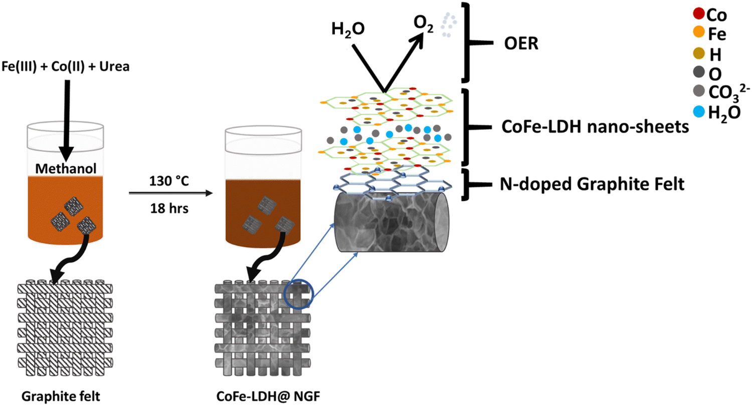 | ||
| Scheme 1 Schematic illustration for the preparation of the CoFe-LDH@NGF electrode. | ||
Results and discussion
X-ray diffraction analysis
The crystal structure of the as-prepared catalysts was investigated by powder XRD. In order to find a suitable solvent for the synthesis of the LDH, two samples were prepared by hydrothermal (CoFe-LDH (Hydro.)) and solvothermal methods using water and methanol as the solvent, respectively. The XRD patterns for both samples are compared in Fig. 1a; it can be observed that different metal oxides, i.e. CoFe2O4, Fe2O3 and Co3O4, are formed along with traces of metal hydroxides when using water as the solvent. No characteristic peak of CoFe-LDH was observed in the hydrothermally synthesized sample. In contrast, a pure phase of CoFe-LDH is obtained when using the solvothermal approach, keeping all other parameters constant except the methanol as a solvent. It is concluded that methanol is the better choice compared to water for synthesis of CoFe-LDH at low temperature. Due to its low boiling point, methanol exerts more vapor pressure than water, even at low temperature, which accelerates the reaction by reducing the activation barrier.47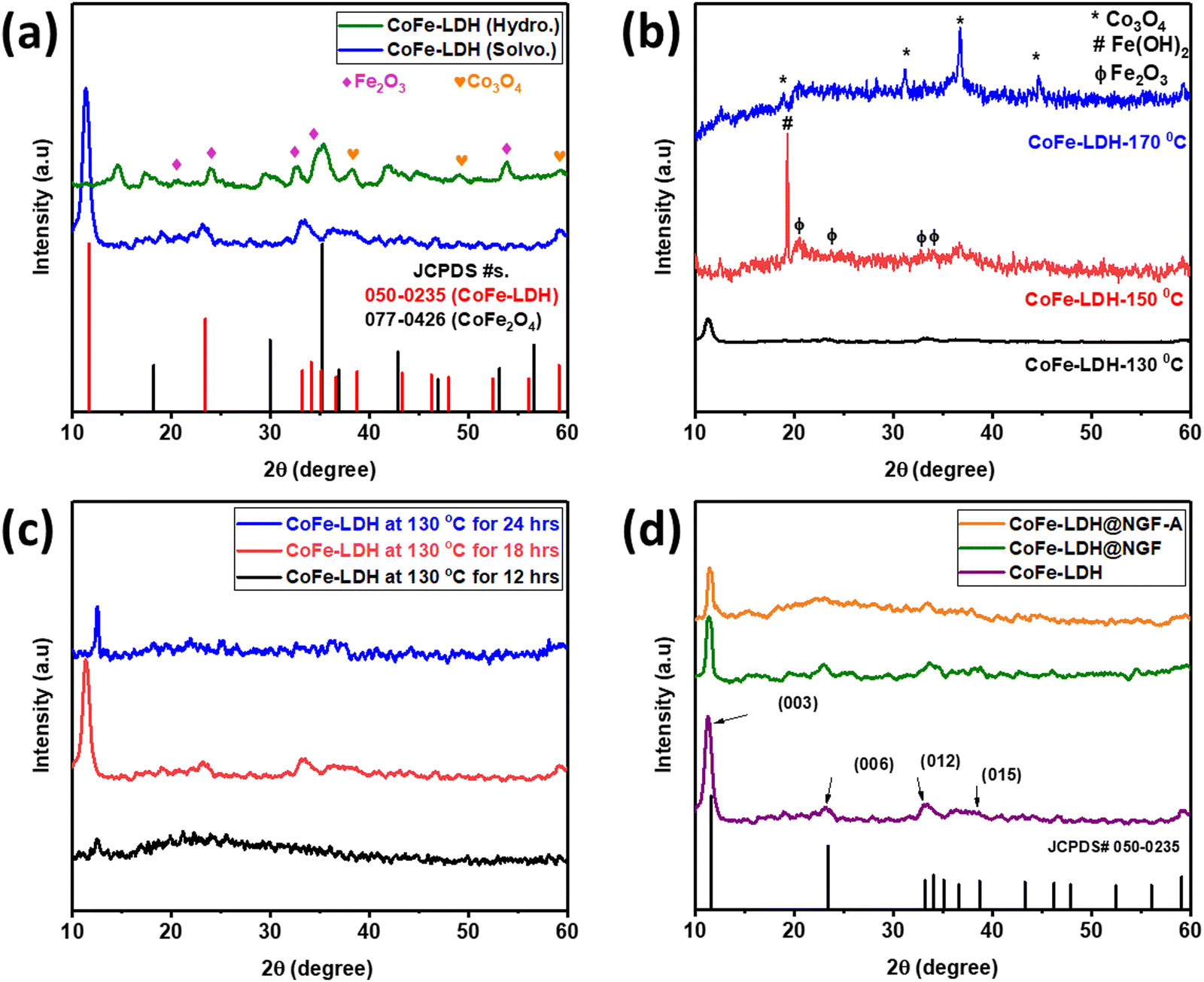 | ||
| Fig. 1 Comparison of XRD spectra for LDH (a) synthesized by hydrothermal (green) and solvothermal (blue) routes, (b) effect of reaction temperature, (c) reaction time and (d) pristine CoFe-LDH with (green), without (purple) adding functionalized felt and annealed powder (orange). | ||
After finding methanol to be a suitable solvent, the reaction temperature and time were optimized. Three samples were prepared at different temperatures [CoFe-LDH-X (X: 130, 150 and 170 °C)] using the same solvothermal route. As shown in Fig. 1b, at elevated temperature (>130 °C), the characteristic peaks of LDH diminish and it decomposes to the respective metal oxides [i.e., iron oxide (Fe2O3) and cobalt oxide (Co3O4)] and hydroxide (Fe(OH)2), as reported in the literature.24 Similarly, the reaction time was also optimized by conducting the reaction for 12, 18 and 24 hours. Less crystalline LDH was formed when the reaction is carried out for 12 hours, only a peak for the (003) plane appeared at an angle of 12.5° and all other planes could not develop properly due to insufficient reaction time, as displayed in Fig. 1c. However, when the reaction time was increased to 18 h, all other planes of LDH appeared; interestingly, the (003) peak is shifted to lower angle (11.3°) as compared to the reference JCPDS No. 50-0235 (11.7°) and other samples. On prolonging reaction time to 24 h, the LDH again decomposed to the respective metal oxides/hydroxides and the (003) peak shifted to a higher angle of 12.5°. Therefore, all other experiments were performed using methanol as the solvent at the optimal temperature of 130 °C for 18 hours.
The XRD pattern of the powdered catalyst prepared by adding functionalized (HNO3 acid-treated) GF is compared with that of the pristine CoFe-LDH (prepared without GF) in Fig. 1d. All the typical crystal planes of CoFe-LDH, namely (003), (006), (012) and (015), appeared at 2θ values 11.3°, 23.1°, 33.45° and 38.6°, respectively. The slight shift in the (003) peak from 11.7° to 11.3° can be attributed to the presence of intercalant carbonate (CO32−) anion between two layers, which also acts as a counter anion between the positively charged brucite-like layers of CoFe-LDH.38 Interestingly, the intensity of the (003) diffraction peak was reduced when functionalized (acid-treated) GF was added during the reaction to make the CoFe-LDH@NGF electrode. This indicates that functional groups (–COOH, –CO–, –OH) present on the acid-treated GF hinder the growth of the layered structure. The annealed sample (CoFe-LDH@NGF-A) also displayed similar behavior.
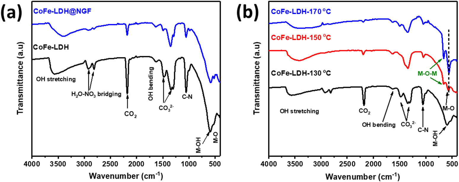
The FT-IR spectra of pristine and CoFe-LDH@NGF are compared in Fig. 2a. The broad bands at 590.12, 1625 and 3480–3000 cm−1 are ascribed to the OH bending/stretching vibrations of brucite-like layered hydroxide and water molecules trapped between the layers. The signals at 1488 and 1350 cm−1 confirm the presence of intercalant CO32− between the two brucite-like hydroxide layers.48 The bands located at 2923.6 and 2815.6 cm−1 can be assigned to H2O–NO3 bridging while the peak at 2185 cm−1 corresponds to CO2 adsorbed from the atmosphere.48,49Fig. 2b shows the FT-IR spectra of pristine CoFe-LDH-X (X: 130, 150 and 170 °C) synthesized at three different temperatures. Beyond the temperature of 130 °C, the signal of M–OH at 590.1 cm−1 disappears and two prominent peaks for M–O and M–O–M (M = Co, Fe) are formed at 557.3 and 655.7 cm−1, respectively.48 Interestingly, these signals are pronounced in the sample prepared at elevated reaction temperature. Additionally, the reduction in the intensity of CO32− signals further confirmed that the brucite-like hydroxide layered structure decomposed to relevant metal oxides, as shown by XRD (Fig. 1b). Similarly, the reduction in the adsorption peak of CO2 at 2185cm−1 in samples prepared at higher temperature means that CO2 is trapped effectively between the layered structure of the LDH.50
 | ||
| Fig. 2 FT-IR spectra of (a) pristine CoFe-LDH and CoFe-LDH@NGF, and (b) samples prepared at different temperatures (i.e. 130, 150 and 170 °C). | ||
The surface morphology of CoFe-LDH prepared at different temperatures was determined using scanning electron microscopy (SEM). The SEM micrograph for CoFe-LDH-130 °C (Fig. 3a) shows that petal-like nanosheets have been grown on the nitrogen-doped GF. However, theses LDH nanosheets are converted to agglomerated metal oxide nanoparticles/flakes when the reaction temperature is increased from 130 to 150 (Fig. 3b) and 170 °C (Fig. 3c). These SEM micrographs validate the XRD and FT-IR results. The formation of these oxides leads to deteriorate electrochemical performance for the OER compared to the layered hydroxide and will be discussed under the electrochemical results section. Similarly, nanosheets are not formed properly with a short reaction time of 12 h (Fig. 3d) or are converted to nanorods of respective metal oxides/hydroxide when the reaction time is prolonged to 24 h (Fig. 3e). The cobalt and Fe ratio (Co:Fe) for pristine CoFe-LDH and the CoFe-LDH@NGF electrode (synthesized at 130 °C) was determined by ICP-OES to be ≈3 (Fig. 3f). The CHNO elemental composition for both samples was also determined by elemental analyzer, as shown in Fig. 3g. The presence of nitrogen (≈2.84%) confirms that it has been successfully doped in GF during the hydrothermal synthesis of CoFe-LDH@NGF.
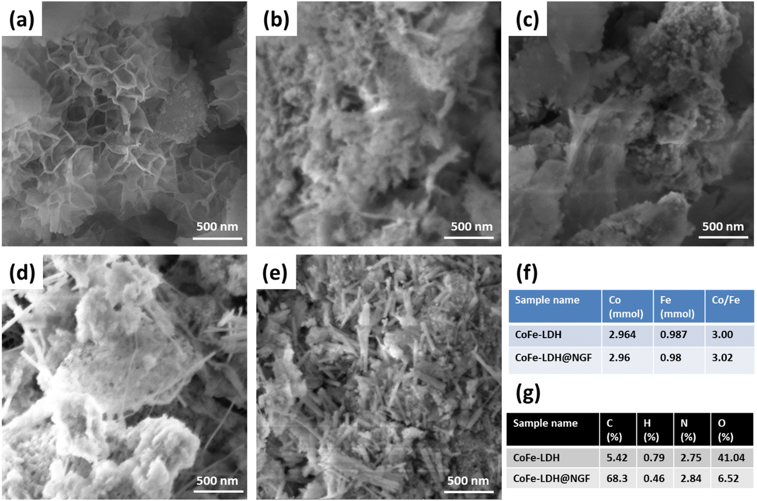 | ||
| Fig. 3 SEM images of CoFe-LDH synthesized at (a) 130, (b) 150 and (c) 170 °C for 18 h. SEM images CoFe-LDH synthesized at 130 °C for (d) 12 h and (e) 24 h. (f) ICP analysis and (g) CHNO composition determined by elemental analyzer for pristine CoFe-LDH and CoFe-LDH@NGF electrodes. | ||
Electrochemical OER performance
The catalytic performance of the as-synthesized electrodes for the OER was measured in 1.0 M KOH (pH 13.69) aqueous solution using a three-electrode system. The overpotential (η) values were calculated by drawing a tangent on the iR-corrected linear sweep polarized (LSV) curves, as shown in Fig. 4a. The pristine CoFe-LDH@A-GF produced a current density of 10 mA cm−2 at an overpotential (η10) of 360 mV, which is equivalent to or better than that of Ce-doped CoFe-LDH (377 mV)51 and CoFe-LDH (404 mV)52 reported in the literature. However, the CoFe-LDH@O-GF displays better OER performance than CoFe-LDH@A-GF and displays η10 of 320 mV, which is equivalent to those of earlier reported CoFe-LDH/rGO (325 mV)53 and 25%La-CoFe-LDH (317 mV)51 catalysts. This improved performance can be attributed to the hydroxyl functional groups (–OH) attached to the oxidized GF (O-GF) as these groups play a vital role in alkaline water splitting. The OER activity is further enhanced when the CoFe-LDH nanosheets are grown on nitrogen-doped GF (CoFe-LDH@NGF) and the η10 reduces to 220 mV overpotential. However, the annealed electrode (CoFe-LDH@NGF-A) outperforms the un-annealed CoFe-LDH@NGF electrode, especially at higher current densities, as displayed in Fig. 4a. This might be due to a synergistic effect between the N-doped GF and the CoFe-LDH nanosheets due to the enhanced electrical conductivity. As nitrogen possesses five valence electrons and can create three covalent bonds with carbon atoms in N-doped GF, its lone pair of electrons in the valence shell significantly enhances the conductivity of the graphite felt. Moreover, nitrogen sits adjacent to carbon in the periodic table, having a similar radius but displaying higher electronegativity. Consequently, introducing nitrogen in the carbon skeleton of the GF results in bond polarity. This disturbs the electronic cloud around the carbon atoms within the GF, leading to enhanced electrical conductivity.54 The η10 values of both CoFe-LDH@NGF (220 mV) and CoFe-LDH@NGF-A (230 mV) are also compared with those of conventional RuO2/NGF (334 mV) and other CoFe-LDH-based electrocatalysts, as shown in Fig. 4a and b. The CoFe-LDH@NGF catalyst needed much lower overpotential (η10) to generate a current density of 10 mA cm−2 in 1.0 M KOH as compared to other electrocatalysts reported in the literature (Table 1).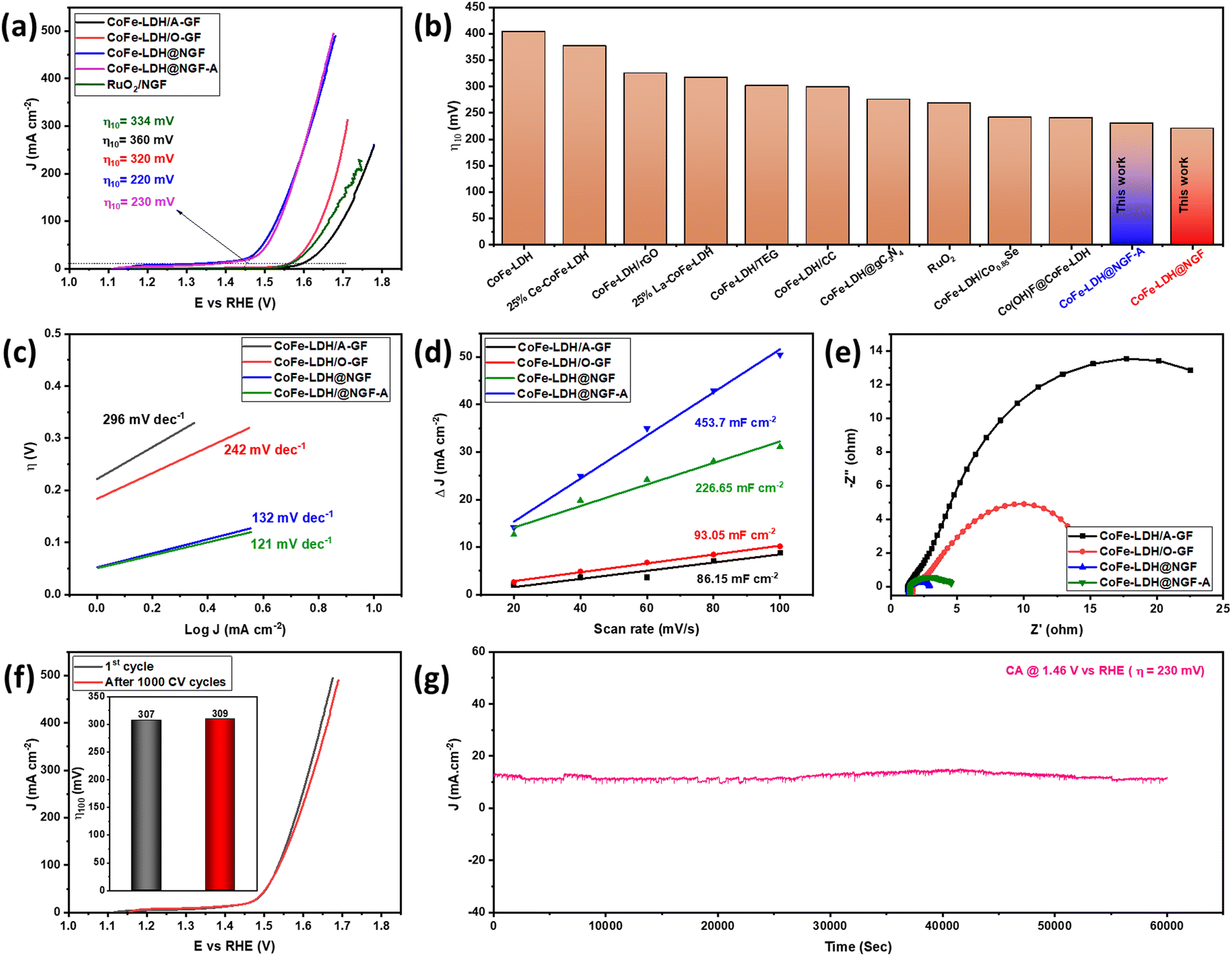 | ||
| Fig. 4 iR-corrected polarization curves (a), comparison of CoFe-LDH@NGF with literature reports (b), comparison of Tafel plots (c), double layer capacitance (Cdl) at different scan rates (d), and EIS Nyquist spectra (e) of CoFe-LDH@A-GF, CoFe-LDH@O-GF, CoFe-LDH@NGF and CoFe-LDH@NGF-A in 1.0 M KOH. Comparison of LSV curves (f) and η100 (inset) before and after 1000 CV cycles (g). Chronoamperometry analysis performed at overpotential of 230 mV. | ||
| Sr. No. | Catalyst | η 10 (mV) | Tafel slope (mV dec−1) | R ct (Ω) | Ref. |
|---|---|---|---|---|---|
| 1. | CoFe-LDH | 404 | N/A | N/A | 52 |
| 2. | 25% Ce-CoFe-LDH | 377 | 134 | 63.5 | 51 |
| 3. | 25%La-CoFe-LDH | 317 | 125 | 37.5 | 51 |
| 4. | CoFe-LDH-TEG | 301 | 52 | 3.39 | 43 |
| 5. | CoFe-LDH/CC | 299 | 52 | 16.5 | 55 |
| 6. | CoFe-LDH@gC3N4 (10%) | 275 | 58 | 97.02 | 56 |
| 7. | RuO2 | 268 | 78 | N/A | 56 |
| 8. | CoFe-LDH/Co0.85Se/CC | 241 | 48 | 2.9 | 55 |
| 9. | Co(OH)F@CoFe-LDH | 240 | 25.4 | N/A | 57 |
| 10. | Cu@CoFe-LDH | 240 | 44.4 | N/A | 58 |
| 11. | IrO2/Cu foam | 250 | 58.4 | N/A | 58 |
| 12. | Co8Fe1 LDH/NF | 262 | 41.9 | 3.9 | 59 |
| 13. | CoFe-LDH-F/NF | 260 | 47 | 30 | 60 |
| 14. | B-α-Co5.8Fe LDH | 264 | 34 | 13.7 | 61 |
| 15. | CoFe-LDH/rGO | 325 | 43 | 7 | 53 |
| 16. | CoFe-LDH/Ni foam | 250 | 35 | 9.5 | 62 |
| 17. | CoFe-LDHs-Ar | 266 | 37.8 | 20 | 63 |
| 18. | CoFe-LDH/A-GF | 360 | 296 | 28.7 | This work |
| 19. | CoFe-LDH/O-GF | 320 | 242 | 13.8 | This work |
| 20. | CoFe-LDH@NGF-A | 230 | 121 | 3.1 | This work |
| 21. | CoFe-LDH@NGF | 220 | 132 | 1.48 | This work |
To determine the electrochemical reaction mechanism and kinetics, Tafel analysis was performed for all electrodes, as shown in Fig. 4c. The Tafel slopes for the CoFe-LDH@NGF (132 mV dec−1) and CoFe-LDH@NGF-A (121 mV dec−1) electrodes are much lower than those for the pristine CoFe-LDH@A-GF (296 mV dec−1) and CoFe-LDH@O-GF (242 mV dec−1) electrodes. The results reveal that all the electrodes follow the Volmer–Heyrovsky mechanism in alkaline media. Similarly, the exchange current densities (J0) at zero overpotential were also determined for all electrodes. The higher J0 values for both CoFe-LDH@NGF-A (0.415 mA cm−2) and CoFe-LDH@NGF (0.381 mA cm−2) compared to those for CoFe-LDH@A-GF (0.181 mA cm−2) and CoFe-LDH@O-GF (0.183 mA cm−2) further confirm that the OER kinetics become faster due to the improved electronic conductivity of the N-doped GF.
Electrochemical surface area (ECSA) is a key parameter for determining the performance for any catalysts and can be calculated from the electrical double layer capacitance (Cdl). A higher ECSA promotes the mass (ion) transfer at the electrolyte–electrode interface, which enhances the rate of the reaction. The Cdl values are calculated from the slope of the plot of ΔJ = Ja − Jc and the different CV scan rates (20, 40, 60, 80, 100 mV s−1) in the potential range of −1.0 and −0.7 V vs. Ag/AgCl. Electrochemical surface area was calculated from Cdl using the formula:
As shown in Fig. 4d, the Cdl and ECSA values for CoFe-LDH@NGF (226.65 mF cm−2, 1416.6 cm−2) are lower than those for CoFe-LDH@NGF-A (453.7 mF cm−2, 2835.6 cm−2), which indicates that annealing of the electrode improves the electrochemical OER performance by enhancing the electrical conductivity and crystallinity of the substrate.64 However, the Cdl and ECSA values for both CoFe-LDH@A-GF (86.15 mF cm−2, 538.43 cm−2) and CoFe-LDH@O-GF (93.05 mF cm−2, 581.56 cm−2) are much lower compared to the in situ growth electrodes, which provides further evidence of the enhanced OER activity of CoFe-LDH@NGF electrodes.
EIS analysis was also performed to determine the charge transfer kinetics. The smaller the diameter of the semicircle of Nyquist plot, the faster the charge transfer process at the electrode–electrolyte interface.65 As shown in EIS spectra (Fig. 4e), CoFe-LDH@NGF displays small charge transfer resistance (Rct ≈ 1.48 Ω) as compared to CoFe-LDH@NGF-A (≈3.1 Ω), CoFe-LDH@O-GF (≈13.8 Ω) and CoFe-LDH@A-GF (≈28.7 Ω). The low Rct of the CoFe-LDH@NGF electrode is attributed to the improved electronic conductivity of the N-doped GF. However, the catalyst CoFe-LDH@NGF-A exhibits more Rct than CoFe-LDH@NGF at the same voltage. This increased resistance and reduced OER performance of the former catalyst compared to the latter in the low overpotential region (Fig. 4a) can be ascribed to the agglomeration of LDH nanosheets. Another important parameter, the electrochemical stability of CoFe-LDH@NGF-A, is determined by scanning 1000 CV cycles in 1.0 M KOH. As shown in the linear sweep voltammetry curves (Fig. 4f), the electrode exhibits good durability with a slight increase in overpotential (η100) from 307 to 309 mV at higher current density of 100 mA cm−2. However, the η10 remains the same. Chronoamperometry (CA) analysis was conducted at an overpotential of 230 mV for 60000 seconds (equivalent to 16.7 hours) to assess the stability of the CoFe-LDH@NGF electrode. As depicted in Fig. 4g, the electrode exhibited consistent performance for the OER in alkaline media for up to 17 hours.
SEM and conventional transmission electron microscopy (TEM) were conducted on CoFe-LDH@NGF samples both before and after the OER stability test. As depicted in the SEM images (Fig. 5a and b), the morphology of the CoFe-LDH nanosheets remained consistent. Furthermore, the TEM images (Fig. 5c and d) revealed that the CoFe-LDH nanosheets retained similar morphology before and after the chronoamperometry stability test.
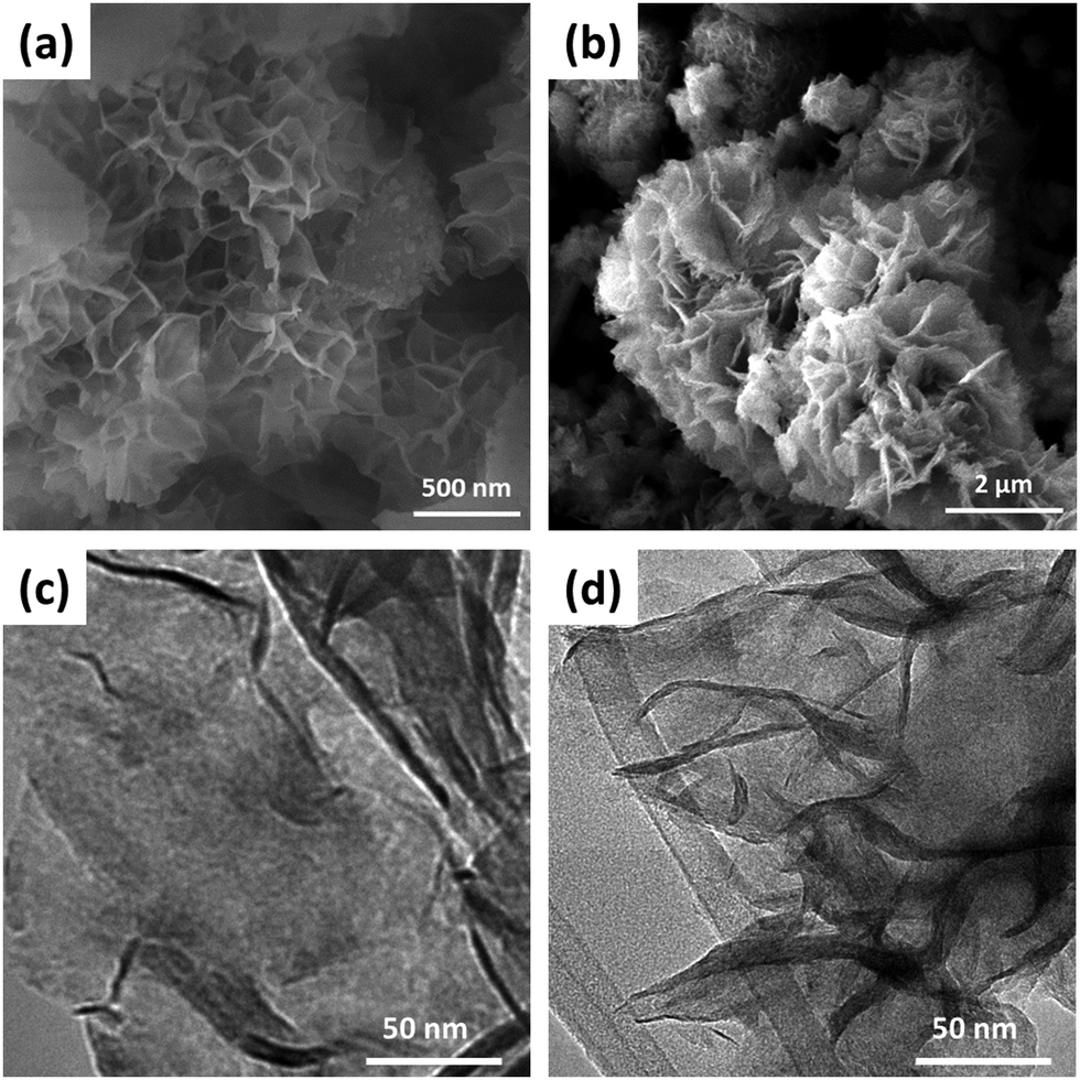 | ||
| Fig. 5 Comparison of SEM images before (a) and after (b) the OER stability test. TEM images of CoFe-LDH nanosheets before (c) and after (d) chronoamperometry analysis. | ||
The OER performance of CoFe-LDH@NGF electrodes prepared at different temperatures (130, 150 and 170 °C) and reaction times (12, 18 and 24 h) was also investigated. As depicted in the LSV curves (Fig. 6a), the electrode synthesized at 130 °C (CoFe-LDH@NGF-130 °C) produces a current density of 10 mA cm−2 at a lower overpotential (220 mV) compared to CoFe-LDH@NGF-150 °C (240 mV) and CoFe-LDH@NGF-170 °C (260 mV). However, the OER activity of CoFe-LDH@NGF-150 °C is enhanced at higher current densities, which can be ascribed to the formation of Fe(OH)2 species after the decomposition of CoFe-LDH, as shown in the XRD plot (Fig. 1b). Similarly, the electrode synthesized at the optimal temperature for 18 hours (CoFe-LDH@NGF-18h) displays η10 (220 mV), which is less than those of CoFe-LDH@NGF-12h (230 V) and CoFe-LDH@NGF-24h (240 mV), as shown in Fig. 6b. The catalyst CoFe-LDH@NGF-170 °C shows higher charge transfer (Rct) and mass transfer (Rd) resistances than the samples synthesized at low temperatures (Fig. 6c). Similarly, the samples synthesized for 12 and 24 hours (Fig. 6d) also display higher Rct and Rd values compared to the sample synthesized for 18 h. The reduced electrochemical performance for the OER with increasing temperature and reaction time can be attributed to the decomposition of the layered hydroxide structure to the respective metal oxide nanoparticle or nanorods, as shown in the XRD plots (Fig. 1) and SEM images (Fig. 3).
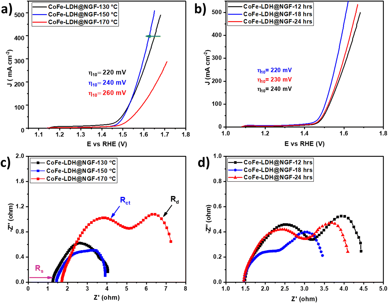 | ||
| Fig. 6 LSV curves for CoFe-LDH@NGF-based electrodes (a) synthesized at different temperatures (130, 150, and 150 °C) and (b) for different reaction times (12, 18 and 24 hours). The EIS spectra for (c) CoFe-LDH@NGF-X (130, 150, and 150 °C) and (d) CoFe-LDH@NGF-X (12, 18, and 24 hours). | ||
Conclusions
In summary, the electrochemical OER performance of CoFe-LDH-based electrocatalysts was improved by growing their nanosheets in situ on N-doped GF using a solvothermal route. The synthetic parameters of reaction solvent, temperature and reaction time were optimized. Pure CoFe-LDH nanosheets are formed when methanol is used as the solvent with the optimal temperature (130 °C) and reaction time (18 h). However, only Co and Fe metal oxides are obtained in the hydrothermal process, as shown in Fig. 1. Moreover, these LDH nanosheets decompose to the respective metal oxides/hydroxides nanoparticles or nanorods with longer reaction times and elevated temperatures. The as-synthesized CoFe-LDH@NGF (130 °C, 18 h) displays excellent electrocatalytic performance and good stability during the OER in alkaline media. It is also observed that the OER performance increases when O-GF is used as a substrate compared to annealed graphite felt (A-GF). Moreover, the overpotential values also reduce at higher current densities when Fe(OH)2 species are formed at elevated temperature (150 °C). The OER activities of both CoFe-LDH@NGF and CoFe-LDH@NGF-A exceed those of CoFe-LDH@A-GF, CoFe-LDH@O-GF, conventional noble metal RuO2, and other CoFe-LDH-based electrocatalysts reported in the literature. This improved performance for CoFe-LDH@NGF is related to the improved charge transfer resistance and ECSA due to the formation of the nanosheets on N-doped GF. Owing to its enhanced electrochemical OER performance in alkaline media, CoFe-LDH@NGF is a potential alternative to expensive noble metals (Ru, Ir) and other transition metal-based electrocatalysts for commercial applications.Author contributions
Conceptualization and supervision, M. A. R. A.; synthesis, N. F. S.; characterization. A. J. and G. H.; resources, M. A. R. A. and M. S. U.; assistance in synthesis, M. J.; writing – original draft, N. F. S.; writing – review and editing, M. A. R. A. All authors have read and agreed to the published version of the manuscript.Conflicts of interest
The authors declare no conflicts of interest.Acknowledgements
This study was financially supported by the Chemistry Division, Directorate of Science, PINSTECH and Pakistan Atomic Energy Commission (PAEC). We also acknowledge the Central Analytical Facility Division for ICP analysis, the Material Division for XRD measurement and the Physics Division, PINSTECH for FT-IR and SEM images of our samples.References
- G. Nicoletti, N. Arcuri, G. Nicoletti and R. Bruno, Energy Convers. Manage., 2015, 89, 205–213 CrossRef.
- M. S. Dresselhaus and I. Thomas, Nature, 2001, 414, 332–337 CrossRef CAS PubMed.
- K. E. Ayers, L. T. Dalton and E. B. Anderson, ECS Trans., 2012, 41, 27 CrossRef CAS.
- M. A. R. Anjum, H. Y. Jeong, M. H. Lee, H. S. Shin and J. S. Lee, Adv. Mater., 2018, 30, 1707105 CrossRef PubMed.
- F. Cheng, J. Shen, B. Peng, Y. Pan, Z. Tao and J. Chen, Nat. Chem., 2011, 3, 79–84 CrossRef CAS PubMed.
- E. Fabbri, A. Habereder, K. Waltar, R. Kötz and T. J. Schmidt, Catal.: Sci. Technol., 2014, 4, 3800–3821 RSC.
- Y. Shi and B. Zhang, Chem. Soc. Rev., 2016, 45, 1529–1541 RSC.
- Y. Yan, B. Y. Xia, B. Zhao and X. Wang, J. Mater. Chem. A, 2016, 4, 17587–17603 RSC.
- V. S. Thoi, Y. Sun, J. R. Long and C. J. Chang, Chem. Soc. Rev., 2013, 42, 2388–2400 RSC.
- B. You and Y. Sun, Acc. Chem. Res., 2018, 51, 1571–1580 CrossRef CAS PubMed.
- Y. Lee, J. Suntivich, K. J. May, E. E. Perry and Y. Shao-Horn, J. Phys. Chem. Lett., 2012, 3, 399–404 CrossRef CAS PubMed.
- P. A. DeSario, C. N. Chervin, E. S. Nelson, M. B. Sassin and D. R. Rolison, ACS Appl. Mater. Interfaces, 2017, 9, 2387–2395 CrossRef CAS PubMed.
- F. Lyu, Y. Bai, Z. Li, W. Xu, Q. Wang, J. Mao, L. Wang, X. Zhang and Y. Yin, Adv. Funct. Mater., 2017, 27, 1702324 CrossRef.
- S. Xu, X. Yu, X. Liu, C. Teng, Y. Du and Q. Wu, J. Colloid Interface Sci., 2020, 577, 379–387 CrossRef CAS PubMed.
- K. Fan, H. Chen, Y. Ji, H. Huang, P. M. Claesson, Q. Daniel, B. Philippe, H. Rensmo, F. Li and Y. Luo, Nat. Commun., 2016, 7, 1–9 Search PubMed.
- X. Long, S. Xiao, Z. Wang, X. Zheng and S. Yang, Chem. Commun., 2015, 51, 1120–1123 RSC.
- G. Liu, P. Li, G. Zhao, X. Wang, J. Kong, H. Liu, H. Zhang, K. Chang, X. Meng and T. Kako, J. Am. Chem. Soc., 2016, 138, 9128–9136 CrossRef CAS PubMed.
- S. Dou, L. Tao, J. Huo, S. Wang and L. Dai, Energy Environ. Sci., 2016, 9, 1320–1326 RSC.
- K. Xu, P. Chen, X. Li, Y. Tong, H. Ding, X. Wu, W. Chu, Z. Peng, C. Wu and Y. Xie, J. Am. Chem. Soc., 2015, 137, 4119–4125 CrossRef CAS PubMed.
- Y. Wang, D. Yan, S. El Hankari, Y. Zou and S. Wang, Adv. Sci., 2018, 5, 1800064 CrossRef PubMed.
- C. Tang, H. F. Wang, X. L. Zhu, B. Q. Li and Q. Zhang, Part. Part. Syst. Charact., 2016, 33, 473–486 CrossRef CAS.
- B. M. Hunter, H. B. Gray and A. M. Muller, Chem. Rev., 2016, 116, 14120–14136 CrossRef CAS PubMed.
- X. Long, Z. Wang, S. Xiao, Y. An and S. Yang, Mater. today, 2016, 19, 213–226 CrossRef CAS.
- J. Yu, Q. Wang, D. O'Hare and L. Sun, Chem. Soc. Rev., 2017, 46, 5950–5974 RSC.
- C. Li, M. Wei, D. G. Evans and X. Duan, Catal. Today, 2015, 247, 163–169 CrossRef CAS.
- X. Yu, M. Zhang, W. Yuan and G. Shi, J. Mater. Chem. A, 2015, 3, 6921–6928 RSC.
- X. Zhu, C. Tang, H.-F. Wang, Q. Zhang, C. Yang and F. Wei, J. Mater. Chem. A, 2015, 3, 24540–24546 RSC.
- R. Yang, Y. Zhou, Y. Xing, D. Li, D. Jiang, M. Chen, W. Shi and S. Yuan, Appl. Catal., B, 2019, 253, 131–139 CrossRef CAS.
- M. Gong and H. Dai, Nano Res., 2015, 8, 23–39 CrossRef CAS.
- J. Jiang, A. Zhang, L. Li and L. Ai, J. Power Sources, 2015, 278, 445–451 CrossRef CAS.
- K.-b Jang, K. R. Park, K. M. Kim, S.-k Hyun, C. Ahn, J. C. Kim, S.-c Lim, H. Han and S. Mhin, Appl. Surf. Sci., 2021, 545, 148927 CrossRef CAS.
- F. Song and X. Hu, J. Am. Chem. Soc., 2014, 136, 16481–16484 CrossRef CAS PubMed.
- F. Song and X. Hu, Nat. Commun., 2014, 5, 1–9 Search PubMed.
- M. S. Burke, M. G. Kast, L. Trotochaud, A. M. Smith and S. W. Boettcher, J. Am. Chem. Soc., 2015, 137, 3638–3648 CrossRef CAS PubMed.
- F. Yang, K. Sliozberg, I. Sinev, H. Antoni, A. Bähr, K. Ollegott, W. Xia, J. Masa, W. Grünert and B. R. Cuenya, ChemSusChem, 2017, 10, 156–165 CrossRef CAS PubMed.
- H. Yang, J. Liu, Z. Chen, R. Wang, B. Fei, H. Liu, Y. Guo and R. Wu, Chem. Eng. J., 2021, 420, 127671 CrossRef CAS.
- Z. Wang, S. Wang, L. Ma, Y. Guo, J. Sun, N. Zhang and R. Jiang, Small, 2021, 17, 2006770 CrossRef CAS PubMed.
- L. Feng, A. Li, Y. Li, J. Liu, L. Wang, L. Huang, Y. Wang and X. Ge, ChemPlusChem, 2017, 82, 483–488 CrossRef CAS PubMed.
- J. Guo, Z. Wei, K. Wang and H. Zhang, Int. J. Hydrogen Energy, 2021, 46, 27529–27542 CrossRef CAS.
- Y. Zhang, J. Xiao, Q. Lv and S. Wang, Front. Chem. Sci. Eng., 2018, 12, 494–508 CrossRef CAS.
- Z. Chen, Y. Ha, H. Jia, X. Yan, M. Chen, M. Liu and R. Wu, Adv. Energy Mater., 2019, 9, 1803918 CrossRef.
- Y. J. Yang, M. Duan, C. Yan, D. Zhao, C. Jiang, X. Duan and X. Song, J. Electroanal. Chem., 2020, 856, 113697 CrossRef CAS.
- C. Yu, X. Han, Z. Liu, C. Zhao, H. Huang, J. Yang, Y. Niu and J. Qiu, Carbon, 2018, 126, 437–442 CrossRef CAS.
- C. Du, M. Shang, J. Mao and W. Song, J. Mater. Chem. A, 2017, 5, 15940–15949 RSC.
- B. Deng, J. Liang, L. Yue, T. Li, Q. Liu, Y. Liu, S. Gao, A. A. Alshehri, K. A. Alzahrani and Y. Luo, Chin. Chem. Lett., 2022, 33, 890–892 CrossRef CAS.
- L. F. Castañeda, F. C. Walsh, J. L. Nava and C. P. de León, Electrochim. Acta, 2017, 258, 1115–1139 CrossRef.
- K. M. Jensen, C. Tyrsted, M. Bremholm and B. B. Iversen, ChemSusChem, 2014, 7, 1594–1611 CrossRef CAS PubMed.
- M. Shabanian, M. Hajibeygi and A. Raeisi, Layered double hydroxide polymer nanocomposites, Elsevier, 2020, pp. 77–101 Search PubMed.
- Y. Otsuka, M. Takeuchi, M. Otsuka, B. Ben-Nissan, D. Grossin and H. Tanaka, Colloid Polym. Sci., 2015, 293, 2781–2788 CrossRef CAS.
- W. Jang, S. Yoon, J. Song, J. Kim, K. An and S. Cho, Cell Rep. Phys. Sci., 2021, 2, 100628 CrossRef CAS.
- M. Rong, H. Zhong, S. Wang, X. Ma and Z. Cao, Colloids Surf., A, 2021, 625, 126896 CrossRef CAS.
- F. Dionigi, Z. Zeng, I. Sinev, T. Merzdorf, S. Deshpande, M. B. Lopez, S. Kunze, I. Zegkinoglou, H. Sarodnik and D. Fan, Nat. Commun., 2020, 11, 2522 CrossRef CAS PubMed.
- X. Han, C. Yu, J. Yang, C. Zhao, H. Huang, Z. Liu, P. M. Ajayan and J. Qiu, Adv. Mater. Interfaces, 2016, 3, 1500782 CrossRef.
- Z. Jialin, L. Yiyang, L. Shanfu and X. Yan, Batteries, 2023, 9, 40 CrossRef.
- W. Jin, F. Liu, X. Guo, J. Zhang, L. Zheng, Y. Hu, J. Mao, H. Liu, Y. Xue and C. Tang, Catal.: Sci. Technol., 2019, 9, 5736–5744 RSC.
- M. Arif, G. Yasin, M. Shakeel, M. A. Mushtaq, W. Ye, X. Fang, S. Ji and D. Yan, Mater. Chem. Front., 2019, 3, 520–531 RSC.
- M. Qin, Y. Wang, H. Zhang, M. Humayun, X. Xu, Y. Fu, M. K. Kadirov and C. Wang, CrystEngComm, 2022, 24, 6018–6030 RSC.
- L. Yu, H. Zhou, J. Sun, F. Qin, D. Luo, L. Xie, F. Yu, J. Bao, Y. Li and Y. Yu, Nano Energy, 2017, 41, 327–336 CrossRef CAS.
- J. Zhao, X.-r Wang, F.-w Chen, C. He, X.-j Wang, Y.-p Li, R.-h Liu, X.-m Chen, Y.-j Hao and M. Yang, Inorg. Chem. Front., 2020, 7, 737–745 RSC.
- P. F. Liu, S. Yang, B. Zhang and H. G. Yang, ACS Appl. Mater. Interfaces, 2016, 8, 34474–34481 CrossRef CAS PubMed.
- Y. Liu, Z. Jin, P. Li, X. Tian, X. Chen and D. Xiao, ChemElectroChem, 2018, 5, 593–597 CrossRef CAS.
- Y. Pei, Y. Ge, H. Chu, W. Smith, P. Dong, P. M. Ajayan, M. Ye and J. Shen, Appl. Catal., B, 2019, 244, 583–593 CrossRef CAS.
- Y. Wang, Y. Zhang, Z. Liu, C. Xie, S. Feng, D. Liu, M. Shao and S. Wang, Angew. Chem., Int. Ed., 2017, 56, 5867–5871 CrossRef CAS PubMed.
- B. B. Gicha, L. T. Tufa, S. Kang, M. Goddati, E. T. Bekele and J. Lee, Nanomaterials, 2021, 11, 1388 CrossRef CAS PubMed.
- C. Hao, Y. Wu, Y. An, B. Cui, J. Lin, X. Li, D. Wang, M. Jiang, Z. Cheng and S. Hu, Mater. Today Energy, 2019, 12, 453–462 CrossRef.
| This journal is © The Royal Society of Chemistry 2023 |