DOI:
10.1039/D3YA00090G
(Paper)
Energy Adv., 2023,
2, 1476-1494
A novel technological blue hydrogen production process: industrial sorption enhanced autothermal membrane (ISEAM)
Received
23rd February 2023
, Accepted 21st July 2023
First published on 17th August 2023
Abstract
A novel technological industrial blue hydrogen production process – the Industrial Sorption Enhanced Autothermal Membrane (ISEAM) process, with the potential to produce constant fuel cell grade hydrogen with a purity of 99.99%, regardless of upstream process upsets, has been modelled using an Aspen Plus simulator and MATLAB (including both thermodynamics and kinetics analysis). The process exhibits a very high hydrogen yield (99%), and methane conversion (99.9%), with a low carbon monoxide footprint (at ppm levels). The results were validated by comparing against experimental data published in the literature. Parametric evaluations were later conducted to identify the optimal operating conditions for the developed blue hydrogen ISEAM process. The required reforming heat is provided by the exothermic carbonation reaction of a sorbent, while chemical looping of the oxygen carrier (metal oxides) provides the regeneration heat required for the saturated sorbent, in a novel multi-tubular packed shell and tube reactor. Pinch analysis shows that the process is auto thermal (so it does not need any external heating utility) and can achieve an extremely high 97.5% thermal and hydrogen production efficiency. The ISEAM process was benchmarked against an industrial steam methane reforming (SMR) plant and the result shows ≥32% improvements in most of the technical parameters that were evaluated. Economic evaluation shows a levelized cost of hydrogen (LCOH) of $2.6 per kg-H2 for the baseline SMR plant compared with $1.3 per kg-H2 for the ISEAM process (a 50% cost reduction). The cost of CO2 removal (CCR) was calculated as $180 per tonneCO2 for the baseline SMR process compared with $33.2 per tonneCO2 (81.6% cost reduction) for the novel process. The novel ISEAM process utilizes mature and existing industry technologies such as desulphurization, pre-reforming, adsorption, membranes, waste heat boilers, and pressure swing adsorption. Because of this, scale-up is easier and some of the challenges associated with the SMR process and integrated sorption enhanced membrane reforming (SEMR) processes are addressed. These include thermodynamic constraints, a high energy penalty, overall process integration, optimization, membrane contamination, carbon deposition and unsteady state operation.
1. Introduction
The burning of fossil fuels and emission of associated greenhouse gases (GHG) into the atmosphere poses a serious threat to the global environment, and contributes to climate change. To meet the United Nations Climate Change target of limiting global warming to 1.5 °C above pre-industrial levels, a drastic reduction in CO2 emissions and significant changes in the energy sector are needed. According to the US Energy Information Administration,1 as of January 1, 2020, there are approximately 206 trillion cubic metres of total world reserves of natural gas. Hydrogen has a vital part to play in the global future energy mix2,3 because of its zero-carbon combustion and its high energy per unit mass (though admittedly, low energy per unit volume at STP). It is estimated that 50% of hydrogen produced worldwide is produced using Steam Methane Reforming (SMR).4 This process is inefficient and thermodynamically limited; it is also a large emitter of CO2, estimated at almost 2% of the global CO2 emissions in 2019.5 Hence, the deployment of an environmentally friendly and economically attractive process6 with a low energy-penalty is of huge interest to researchers. Various research studies have been carried out to address the limitations of steam methane reforming (SMR)7,8 which include Sorption Enhanced Reforming (SER),9–29 Membrane Reforming (MR),17,25,30–33 integrated Sorption Enhanced Membrane Reforming (SEMR)34,35 and Gas Switching Reforming (GSR). Abanades et al.24,36–38 proposed the use of Ca/Cu looping in a single reactor through a three-step process; (a) sorption enhanced reforming with simultaneous carbonation of CaO; (b) oxidation of Cu to CuO with air; (c) calcination of CaCO3 during the reduction of CuO with a fuel gas.39 The exothermic carbonation of CaO and the exothermic oxidation of Cu to CuO supply the required reforming and calcination heat respectively. In situ removal of CO2 during the reforming step increased the methane conversion. One of the main practical challenges of Ca/Cu looping which this current paper addresses in the SER unit of the novel process, is the elimination of the potential venting of CO2 to the atmosphere as a result of decomposition of CaCO3 during the oxidation step. Shahid et al.40 investigated the sorption-enhanced reforming (SER) performance in a packed bed reactor for three CO2 sorbents such as calcium oxide (CaO), lithium zirconate (LZC) and hydrotalcite (HTC). They concluded that CaO-based sorbents exhibited optimum conditions of 627 °C and 300 kPa with methane conversion of 82% and hydrogen purity of 85%. LZC and HTC were suitable under optimal conditions of 500 kPa and 500 °C with a methane conversion range of 91.2–94.1% and hydrogen purity of 55.1–77.8%, which exceeds the performance of the SMR process under similar operating conditions. Diglio et al.41 investigated SER with 1D numerical modelling in a fixed bed reactor network, packed with the Ni-catalyst/Ca-sorbent operated under cyclical carbonation/reforming and calcination conditions using a pressure swing at 700 °C. During the carbonation/reforming mode, the reactor's feed was a mixture of methane and steam at a high pressure of 3500 kPa. To shift the equilibrium to calcination, the reactors were fed with a mixture of steam and CO2 at a reduced reactor pressure of 100 kPa. Six stages of cyclic operation of the reactor were required: (1) carbonation (CS); (2) purging (PS) for hydrogen removal; (3) depressurisation (D) to obtain a vacuum condition in the bed; (4) calcination (CAS); (5) purging for removal of steam and CO2 and (6) pressurisation (PR) to raise the pressure to the carbonation/reforming pressure of 3500 kPa. The results showed that at least 8 reactors in parallel were required to produce a hydrogen purity of 92% with an average hydrogen yield of 2.9 molH2 per molCH4. Nazir et al.42 developed a gas switching reforming (GSR) process where a cluster of several standalone reactor cycles through three steps: oxygen carrier reduction by PSA off-gas, steam methane reforming, and oxidation with air. The GSR hydrogen process was claimed to have 3% higher equivalent hydrogen production efficiency and an efficiency penalty of 0.3% for 96% CO2 capture when compared to SMR. Silva et al.43 through dynamic mathematical modelling showed that a methane conversion of 99.85% and a hydrogen yield of 1.626 molH2 per mol CH4 (steady state) could be achieved at a temperature of 550–600 °C in a fixed bed membrane reactor because of in situ removal of hydrogen relative to a methane conversion of 88.87% and a hydrogen yield of 1.445 molH2 per mol CH4 (steady state) at 725–950 °C for a conventional SMR reactor. Kim et al.44 developed an industrial high permeable Pd-alloy membrane which was prepared on tubular-porous stainless steel (PSS) 12.7 mm in diameter and a membrane thickness of 6 μm using electroless plating (ELP) of Pd and Ru. Hydrogen permeance after a long-term reforming test was 0.00346 Mol m−2 Pa0.5 which is quite high compared with other reports. Ye G. et al.45 and Shafiee et al.46 modelled an MR using a sequential model with sub-membrane reactors and sub-separators. Parametric investigations showed that in situ hydrogen removal breaks the thermodynamic constraints and improved hydrogen yield and methane conversion, especially at a high permeation capacity. Lee et al.4 developed an integrated SEMR process with membrane and sorption enhancement in a single reactor. Techno-economic simulation showed that simultaneous in situ removal of CO2 and hydrogen from the reaction zones produces the highest methane conversion and hydrogen yield compared with Membrane Reactor (MR) only, Sorption Enhanced Reactor (SER) only, and an SMR process. Ji et al.47 used Computational Fluid Dynamics (CFD) to prove that SEMR not only decreased the CO2 emission and CO poisoning of the catalyst and membrane, but also increased the hydrogen yield, methane conversion and reaction kinetics for both the reforming and water gas shift reactions. The CO mol fraction decreased by 1 order of magnitude in the SEMR compared to the traditional membrane reactor, which minimized the possibility of hydrogen permeation decay.
Dou et al.48 proposed a sorption-enhanced chemical looping steam reforming of glycerol with CO2in- situ capture and utilization through a dry methane reforming process (SE-CLSR + MDR). The process was operated in three stages. The first stage is a typical sorption-enhanced chemical steam reforming process at 650 °C, utilizing NIO/NiAl2O4 as catalysts, calcined dolomite as the sorbent and glycerol as the feedstock. The second stage process was the simultaneous calcination of CaCO3 at 850 °C and dry methane reforming by the use of methane feedstock using the reduced NI/NiAl2O4 as catalysts. The last stage included the oxidation stage where the deposited carbon on the catalyst was oxidised using pure oxygen and the reduced nickel catalyst is re-oxidised to nickel oxide. The results demonstrated that hydrogen of above 92.5% could be generated through a one-step process and CO2 decreased to zero in the pre-CO2 breakthrough periods improving the economics and lower impact on the environment. The proposed process (SE-CLSR + MDR) has some similarities with the novel ISEAM process such as use of calcined dolomite for in situ CO2 removal, chemical looping technology and the use of multiple reactors simultaneously in order to operate the process in a steady state. However, the ISEAM process differs in the main feedstock (methane), process integration, higher feedstock conversion and yield, application of chemical looping combustion which is only used to generate the required calcination heat through an in-direct heat transfer with the main process, the use of a hydrogen-permselective palladium membrane reactor to drive the overall conversion to 99.9%, the use of air in a novel multi-tubular reactor with no risk of diluting the recovered CO2 during the calcination stage as against the use of pure oxygen in the Dou et al. process which requires energy intensive and a costly air separation unit.
The goal of this paper is to propose a novel industrial sorption enhanced autothermal membrane (ISEAM) process as an alternative to the leading industrial steam methane reforming process. The novel process addresses the limitations of the SMR process, such as thermodynamic equilibrium constraints, catalyst deactivation and high energy penalty. In addition, it addresses problems associated with the sorption enhanced membrane reforming (SEMR) process, such as membrane contamination, carbon deposition, unsteady state operation and overall process integration.
2. Methodology
2.1 Baseline SMR process description
Fig. 1 shows a block flow diagram of a baseline SMR plant with an amine unit integrated to remove the CO2. Natural gas as per Table 1 and steam are converted to H2 and CO in a steam reforming process under severe conditions of temperature of 800–1000 °C and pressure of 2000–3500 kPa in the presence of a nickel alumina catalyst.
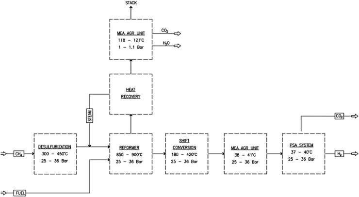 |
| | Fig. 1 Block flow diagram of the steam methane reforming (SMR) process. | |
Table 1 Baseline plant data49
| Components |
Mole (%) |
| C1 |
77.42 |
| C2 |
13.27 |
| C3 |
5.76 |
| CO2 |
2.29 |
| N2 |
0.63 |
| n-C4 |
0.36 |
| i-C4 |
0.23 |
| n-C5 |
0.02 |
| i-C5 |
0.02 |
| Feed gas, kmol h−1 |
287.6 |
| S/C |
2.9 |
The steam reforming stage is followed by two water-gas-shift (WGS) reaction steps to maximize the conversion of CO to H2 and by a final pressure swing adsorption (PSA) unit to produce hydrogen with a purity of 99.9%. An amine unit is added downstream of the water gas shift (WGS) reactor and reaction furnace (RF) to capture the CO2 produced from the process and the flue gas.
2.2 Novel process description
As shown in Fig. 2 and 3, natural gas with feed compositions as per Table 1 is compressed to 3600 kPa and 93 °C and heated through a shell and tube heat exchanger to 380 °C before being fed into a feed gas pre-treatment unit where organic sulfur is removed and heavy hydrocarbons are converted into a mixture of methane, carbon dioxide, carbon monoxide and hydrogen over a nickel oxide catalyst.50 Desulphurization of the feed gas is required to prevent poisoning of the reformer catalyst. The pre-conditioned natural gas feedstock is heated through a series of heat exchangers using the hot effluent retentate and permeate gas from the downstream Pd-alloy membrane catalytic reactor. This is mixed with HP steam produced from the waste heat boiler (WHB). The combined natural gas and HP steam is superheated to 500 °C and routed to the multi-tubular adiabatic packed bed Carbonator-SMR Catalytic Reactor. The reactor is a shell and tube, with packed solid sorbent such as CaO and Ni/Al2O3 catalyst in the tube side and packed oxygen carrier (metal oxides) such as CuO/Al2O3 in the shell side. The Carbonator-SMR Reactors are 3 × 100% regenerative packed bed reactors, with one in the adsorption-reforming mode, the second in the regeneration-oxidation mode and the third in the cooling/stand-by mode. The reactions in the tube side of the Carbonator SMR Reactor are auto thermal as the exothermic carbonation reaction produces the required heat for the endothermic reforming reactions.
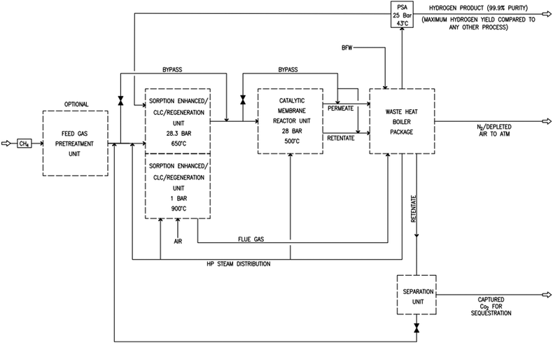 |
| | Fig. 2 Novel industrial sorption enhanced auto-thermal membrane (ISEAM) process. | |
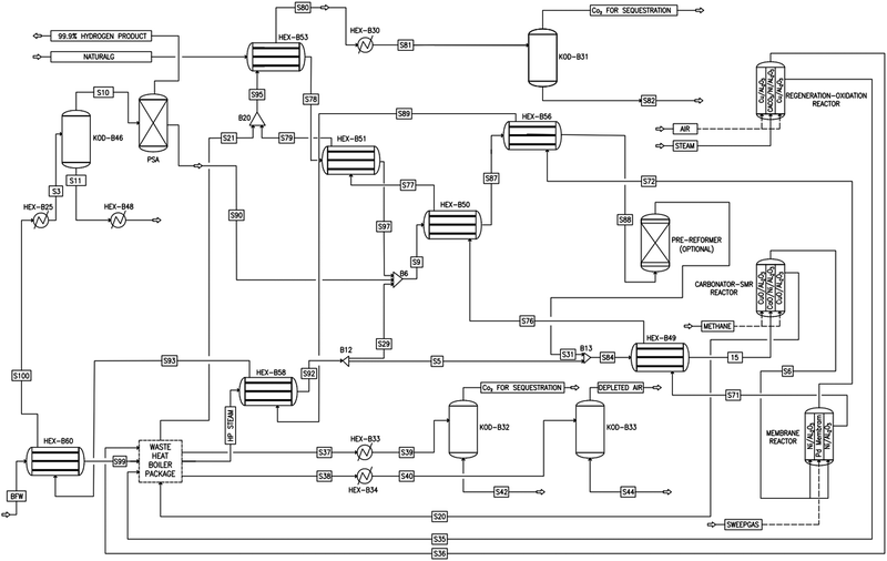 |
| | Fig. 3 Process flow diagram of a novel industrial sorption enhanced auto-thermal membrane (ISEAM) process. | |
Tube side reactions:
| |  | (R1) |
| |  | (R2) |
| |  | (R3) |
| |  | (R4) |
Shell side:
| |  | (R5) |
The main reactions that occur in the Carbonator-SMR catalytic Reactor during the regeneration-oxidation mode are:
Tube side:
| |  | (R6) |
Shell side:
| |  | (R7) |
In situ removal of CO
2 in the Carbonator-SMR Reactor shifts the reforming and water gas shift reactions to the forward direction as per Le Chatellier's principle, leading to an increased hydrogen yield and methane conversion. The use of a sorption enhanced reforming unit has the potential to introduce unsteady state transient operation.
Fig. 4 shows a typical behaviour of the Carbonator-SMR Reactor. Three typical periods of interest are identified: period 1 between 0 <
t < 1000 s typical, transient period between 1000 <
t < 2000 s, and period 2
t > 2000 s. Period 1 (0 <
t < 1000 s) is the pre-breakthrough stage, which is characterized by fast kinetics as the active surface area of the sorbent (CaO) is available leading to higher hydrogen production. The transient period is the breakthrough stage (1000 >
t < 2000 s). This stage is characterized by slow kinetics as the carbonation reaction is controlled by the diffusion through the solid product (CaCO
3) layer. The CaO conversion rate is reduced as more product (CaCO
3) is formed and deposited on the active surface of the CaO. This leads to a decline in the product hydrogen. The last stage is the post-breakthrough (
t > 2000 s); during this stage, the CaO sorbent is saturated and hence there is a total loss of sorption, and the reactions return to those of conventional steam methane reforming.
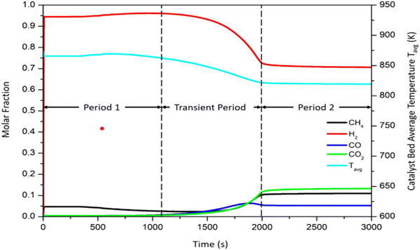 |
| | Fig. 4 Typical product plot for 100% sorption enhanced reforming process.51 | |
To run the 3 × 100% Carbonator-SMR Reactor in the steady state mode, switching between adsorption and calcination is carried out within period 1. This can be done automatically based on time or started by the reactor outlet gas analysers depending on the CO2 concentration in the product gas. The product gas mixture from the tube side of the Carbonator-SMR Reactor leaves at a temperature of 580–650 °C before being routed to the Pd-Alloy catalytic Membrane Reactor, packed with the Ni/Al2O3 catalyst, where further reforming and water gas shift reactions occur. The reforming heat in the Pd-alloy membrane Reactor is provided by the sensible heat of the gas from the upstream Carbonator-SMR Reactor. Steam is used as a sweeping gas to enhance the permeation of hydrogen through the Pd-Alloy Membrane Reactor. Like the Carbonator-SMR Reactor, in-situ removal of the product hydrogen from the reaction zones of the Membrane Reactor results in a further increase of hydrogen yield and methane conversion in accordance with reactions (R1)–(R3). The permeated gas from the Membrane Reactor contains mainly hydrogen and steam, which is used to pre-heat the feed gas and boiler feed water. To achieve a continuous high quality fuel cell hydrogen purity grade of 99.99% regardless of the transient behavior of the process, the cooled permeating gas is routed through a Pressure Swing Absorber (PSA) for final purification and polishing. The retentate gas from the Pd-alloy membrane contains mainly CO2 and steam, which is separated by cooling and the use of a knock-out drum. The heat required for calcination is provided by the exothermic heat of the chemical looping combustion of Cu/CuO or any other oxygen carriers such as NiO and FeO in the presence of an Al2O3 catalyst. The sorption enhanced reforming (SER) unit of the ISEAM process is different from the conventional Ca/Cu looping proposed by Abanades et al.,38 as the sorbent in the novel process is charged into a novel multi-tubular section of the Carbonator-SMR Reactor while the oxygen carrier (metal oxide) is loaded in the shell side of the reactor, providing the required calcination heat through indirect heating; thus, eliminating the problem of potential venting of CO2 to the atmosphere as a result of decomposition of CaCO3 during the oxidation step associated with conventional Ca/Cu looping. The process uses mature and existing industry technologies such as a desulphurization unit, pre-reforming unit, adsorption, membrane unit, waste heat boiler and PSA unit.
2.3 ISEAM process heat integration
Pinch analysis is an energy optimisation technique where cold and hot streams are matched for the purpose of optimum utilization of the process heat energy, and enables the determination of the minimum utility heating and cooling duties required by the process. This makes it possible to design an optimal heat exchanger network, reducing both capital and operation costs. Pinch analysis was conducted using an Aspen Energy Analyser for the ISEAM process. A minimum temperature approach of 10 °C was used. A required minimum process temperature of 37 °C is dictated by the PSA unit and the maximum process temperature of 900 °C is dictated by the regeneration unit of the Carbonator SMR Reactor. The heat needed for regeneration (calcination) is provided by the exothermic chemical looping combustion reaction as per reaction (R7). The external cooling water supply temperature is taken as 20 °C. Significant opportunities for heat integration were identified as shown in Fig. 6 and briefly outlined below for the main streams:
(1) Hot effluent gas (mostly depleted air) at a temperature of 960 °C from the shell side of the regenerator-oxidation reactor (air reactor) is used in the waste heat boiler to produce process steam from boiler feed water.
(2) Hot effluent gas (mostly CO2) at a temperature of 928 °C from the tube side of the regenerator reactor (fuel reactor) is used in the waste heat boiler to produce process steam from boiler feed water.
(3) Hot permeate product gas at a temperature of 500 °C from the Pd-alloy membrane reactor (stream S72) is matched with cold pre-reforming feed gas (stream S87)
(4) Hot retentate product gas (stream S71) at a temperature of 500 °C from the Pd-alloy membrane is used to preheat the feed gas (stream S84) to the SMR-Carbonator Reactor. Fig. 5 shows the composite curve and Fig. 6 shows the heat exchangers grid diagram.
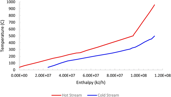 |
| | Fig. 5 ISEAM process composite curve. | |
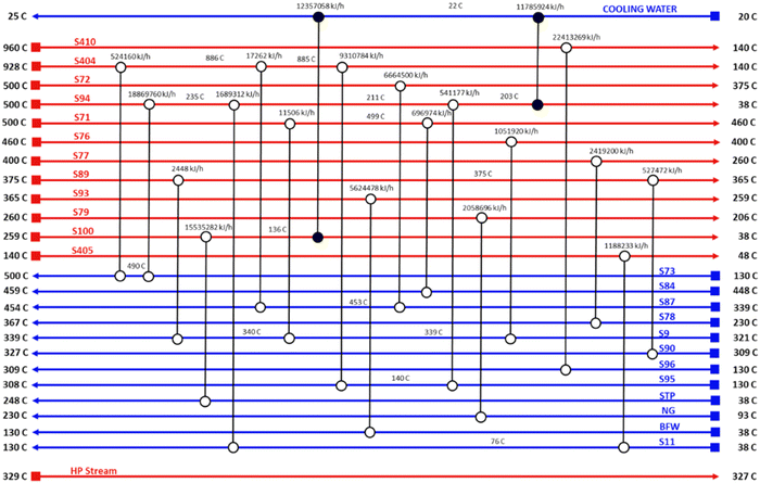 |
| | Fig. 6 ISEAM process heat exchanger grid diagram. | |
(5) As shown in the heat exchanger grid diagram (Fig. 6), there is no external added heating utility required, making the process auto thermal.
2.4 Process modelling and simulation
A steady state thermodynamic equilibrium and kinetic model was developed using integrated Aspen Plus and MATLAB software and used to model and evaluate the baseline SMR plant and the novel process based on a 1-D heterogenous reactor model. Data in Table 2 was used for the novel ISEAM process modelling. Steam methane reforming rate kinetic models (Table 11 in Appendix B) developed by Xu et al.52 in the presence of a Ni/Al2O3 catalyst based on the Langmuir–Hinshelwood Hougen Watson (LHHW) mechanism was adopted and used for the kinetic modelling. Carbonation kinetic rate and data was adopted from a study by Rodriguez et al.53 The hydrogen permeation through the membrane was modelled using Sievert's law (eqn (27) in Appendix B), and the membrane parameters and permeance developed by Kim et al.44 were used because of the high permeance value and suitability for industrial application.
Table 2 System and operating specifications for the novel ISEAM process
| Parameter |
Value |
Units |
| Membrane reactor |
| Number of reactors |
2 × 50% |
— |
| Reactor pressure |
2800 |
kPa |
| Reactor inlet temperature |
580–650 |
°C |
| Permeate inlet pressure |
2500 |
kPa |
| Membrane tube diameter |
0.09 |
M |
| Membrane thickness |
6 |
μm |
| Tube length |
23.5 |
M |
| Number of tubes |
80 |
— |
| Pressure difference between permeate and retentate |
250 |
kPa |
| Membrane permeance44 |
0.00346 |
Mol m−2 s Pa0.5 |
|
|
| Carbonator SMR reactor |
| Number of reactors |
3 × 100% |
— |
| Reactor pressure |
2800 |
kPa |
| Reactor inlet temperature |
500 |
°C |
| Tube diameter |
0.1143 |
m |
| Tube length |
7 |
m |
| Number of tubes |
40 |
|
| Reactor temperature |
500 |
°C |
2.5 Economic evaluation
Economic evaluation of the baseline SMR process and the novel ISEAM process (base and optimised) were conducted following the method proposed by the Global CCS Institute54,55 using key economic indicators such as the cost of CO2 avoided (CCA), cost of CO2 removal (CCR) and levelized cost of hydrogen (LCOH).56 These costs were calculated using eqn (1)–(5).5,42 The fixed charge factor (FCF) converts the total capital requirement into uniform annual amounts at a discount rate over the lifetime of the plant. Total capital requirement (TCR), commonly referred to as CAPEX, is calculated using the installed cost for main equipment and the assumptions stated in Tables 3 and 4. Balance of Plant (BOP) cost include the cooling system, fuel, electricity, storage, make-up water, sanitary system, water discharge and solid wastes, etc. Bare equipment costs were obtained from various works5,42,57–61 and adjusted to the year 2022 using eqn (5),5 and the IHS global capital cost escalation index factor was applied. Assumptions used for the fixed operating and maintenance cost (FOM) and variable operating and maintenance cost (VOM) are summarised in Table 5.| |  | (1) |
| |  | (2) |
| |  | (3) |
| |  | (4) |
| |  | (5) |
Table 3 Parameters and assumptions for economic analysis (CAPEX)
| Equipment |
Number required |
Bare equipment cost (BEC), $1000 |
Ref. |
| SMR reactor |
1 |
57![[thin space (1/6-em)]](https://www.rsc.org/images/entities/char_2009.gif) 841 841 |
60
|
| Sulfur polisher (ZnO) |
1 |
243 |
60
|
| Primary air compressor |
2(1) |
861 |
60
|
| Water gas shift reactor |
4 |
12![[thin space (1/6-em)]](https://www.rsc.org/images/entities/char_2009.gif) 918 918 |
60
|
| MDEA CO2 unit (95% CO2 removal) |
2 |
95![[thin space (1/6-em)]](https://www.rsc.org/images/entities/char_2009.gif) 985 985 |
60
|
| MEA CO2 unit (90% CO2) removal |
2 |
68![[thin space (1/6-em)]](https://www.rsc.org/images/entities/char_2009.gif) 176 176 |
60
|
| PSA unit |
2 |
38![[thin space (1/6-em)]](https://www.rsc.org/images/entities/char_2009.gif) 047 047 |
60
|
| Boiler package |
1 |
7306 |
60
|
| Carbonator (k€2017) |
1 |

|
59
|
| Calciner (k€2017) |
1 |
415. (Fuel thermal input (MWth))0.65 |
59
|
| Membrane reactor |
1 |
$4203.75/surface area (m2) |
4
|
Table 4 Parameters and Assumptions for Economic analysis (CAPEX)
| Equipment |
Number required |
Bare equipment cost (BEC), $1000 |
Ref. |
| Capital cost escalation factor |
2007:170 |
IHS Markit (downstream) |
| 2017:182 |
| 2020:205 |
| 2022:210 |
| Capacity factor (CF) |
0.95 |
5
|
| Plant design life |
25 years |
|
| Discount rate |
12% |
5
|
| Engineering, procurement, and construction cost (EPCC) |
8% of bare erected cost (BEC) |
42
|
| Process contingency |
30% of BEC for MDEA unit, MEA unit, carbonator-reactor and membrane reactor; 0% for reference SMR plant |
42
|
| Project contingency |
10% of (BEC + EPCC + process contingency) |
42
|
| Balance of project (BOP) |
15% of (BEC + project contingency) |
60
|
| Total contingencies |
Project contingency + process contingency |
42
|
| Total plant cost (TPC) |
BEC + EPCC + total contingencies + BOP |
42
|
| Owner's cost |
20.2% of TPC |
42
|
| Total overnight cost (TOC) |
TPC + owner's cost |
42
|
| Total capital requirement (TCR) |
1.14 × TOC |
42
|
Table 5 Parameters and assumptions for economic analysis (OPEX)
| Description |
Values |
Ref. |
| Operating labour |
$60000 per person-year |
42
|
| Operator per shift |
16 |
60
|
| Total shift per day |
2 |
60
|
| Maintenance, support, and administration |
2.5% TOC |
42
|
| Property taxes and insurance |
2% TOC |
42
|
| Fuel cost |
$2.58/MMBTU |
4
|
| Variable operating and maintenance cost (VOM) |
10% of TOC |
|
3. Results and discussion
3.1 Model validation
The baseline kinetic model of the SMR process was validated using actual plant data adopted from Salem et al.49 The validation results for the baseline SMR process (Fig. 7 and 8) show that the kinetic model compares well with the actual plant data, with the kinetic model predicting approximately 3% higher methane conversion and hydrogen yield. The sorption enhanced reforming unit model for the ISEAM process was validated using experimental data (Table 9) reported by Lee et al.62 and the model for the Pd-alloy membrane was confirmed using experimental data (Table 10) reported by Kim et al.44 The ISEAM kinetic model was validated using the thermodynamic equilibrium model as shown in Fig. 9 and kinetics model results compare very favourably with the equilibrium results.
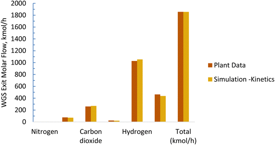 |
| | Fig. 7 Baseline WGS model validation. | |
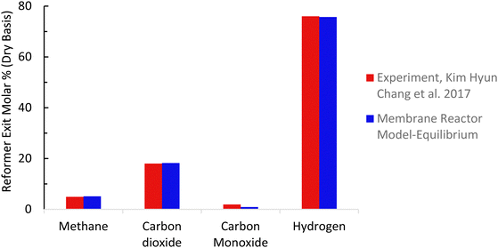 |
| | Fig. 8 Membrane reactor model validation. | |
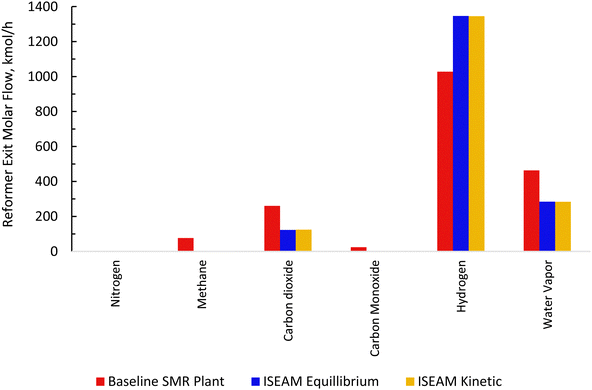 |
| | Fig. 9 Comparison between the baseline SMR and novel ISEAM Process plant and novel ISEAM. | |
3.2 Thermodynamic evaluation of the novel ISEAM process and baseline SMR process
The novel ISEAM process was compared with the baseline industrial SMR process in terms of methane conversion, hydrogen yield, hydrogen purity, hydrogen thermal efficiency and process thermal efficiency using eqn (6)–(9),40,63,64 where ‘n’ stands for relevant molar flowrates. Heating values for 100% natural gas (CH4) and 100% hydrogen gas are simulated in Aspen Plus with standard conditions of 891.6 MJ kmol−1 and 286 MJ kmol−1 respectively. The results presented in Fig. 9, 10 and Table 6 show that the methane conversion and percentage hydrogen yield is higher by 32% for the novel ISEAM process compared with the baseline SMR process as the thermochemical reversible equilibrium constraints that limit the reforming and water gas shift reactions is broken by the in-situ CO2 and hydrogen removal. The process thermal efficiency is higher by 41% and the hydrogen production efficiency is higher by 15.8% for the novel process since there is no external heating utility required as the process is fully heat integrated. The process thermal efficiency achieved in the ISEAM process (97.5%) is among the highest compared with typical values of 48–80% reported in the literature for other alternative processes.42,57,58 A higher thermal efficiency is achieved using chemical looping combustion (CLC) which provides the regeneration heat, careful heat integration, and CO2 removal (mainly) by the use of a cooling and a knock-out drum (KOD). A hydrogen purity of 99.99% is maintained throughout regardless of the upstream upset or reaction extent by the use of a Pressure Swing Adsorption (PSA) unit for both the baseline SMR and novel process.| |  | (6) |
| |  | (7) |
| |  | (8) |
| |  | (9) |
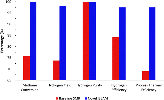 |
| | Fig. 10 Comparison between the baseline SMR process and novel ISEAM process. | |
3.3 ISEAM process reactor performance
The Carbonator-SMR Reactor is modelled as a packed bed adiabatic catalytic reactor and the membrane reactor is modelled as an iso-thermal catalytic plug flow reactor. Both reactors are characterised with one-dimensional heterogeneous equations. The products profile in the Carbonator-SMR reactor during the pre-breakthrough steady state is shown in Fig. 11. Because of the exothermic carbonation reaction,  , the reactor temperature initially increased to a maximum value of 595 °C within the first 1 m of the reactor length, resulting in faster initial kinetics. The reaction rates become slow afterward as the endothermic reforming dominates. The hydrogen molar fraction rises quickly initially from 19.4% (dry basis) close to the reactor inlet and continues to increase slowly along the reactor length, leaving the Carbonator-SMR reactor at 87% (dry basis). The methane molar fraction drops very quickly initially from 69.5% (dry basis) close to the reactor inlet and continues to decrease slowly along the reactor length, leaving the reactor at 12.7% (dry basis). Fig. 12 shows the Membrane Reactor performance; the reforming and water gas shift reactions are at the slowest rate between the membrane reactor length of 0–8 meters because of the high molar flowrate of hydrogen within these reaction zones (22–87%). The permeation of hydrogen is however at the highest at these locations because of a higher retentate hydrogen partial pressure. As more hydrogen is removed in situ from the reaction zones along the membrane reactor, this leads to more methane conversion (and a reduction of methane molar flowrate) and more hydrogen production as per Le-Chatelier's principle. Hydrogen permeation is identified as being as critical as hydrogen selectivity in the design of the Membrane Reactor as more than an average of 54.5% of produced hydrogen was required to be removed from the reactor reaction zones to break the thermochemical reversible equilibrium constraints and shift the reforming reactions to the forward direction.
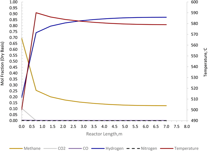 |
| | Fig. 11 Carbonator-SMR reactor product profile for the novel ISEAM process (pre-breakthrough steady state). | |
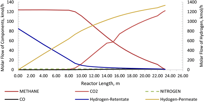 |
| | Fig. 12 Membrane reactor product profile for the novel ISEAM process (molar flow of CO2, CO, N2, H2-retentate, and H2-permeate). | |
3.4 Parametric investigations of the novel ISEAM process
Thermodynamic investigations were conducted to determine the optimal operating conditions for the novel process as shown in Fig. 13. A molar ratio of steam to methane is used to control carbon deposition and to ensure forward reactions of steam methane reforming. A steam to methane ratio between 1 and 5 was investigated and Fig. 13(a) shows that an S/C ratio of 3.75–5 gives maximum methane conversion and hydrogen yield. Purge gas is used in the Membrane Reactor to enhance the driving force and to reduce the hydrogen partial pressure in the permeate side, consequently increasing hydrogen permeation as shown in Fig. 13(b) and (c) where the methane conversion and hydrogen yield increases with increasing purge gas (sweep gas). The overall steam methane reforming reaction  is endothermic and is favored by high temperature, as shown in Fig. 13(d). For a Carbonator-SMR Reactor and Membrane SMR Reactor temperature of 550 °C, the process achieves the maximum methane conversion and hydrogen yield of 99.9% Table 6.
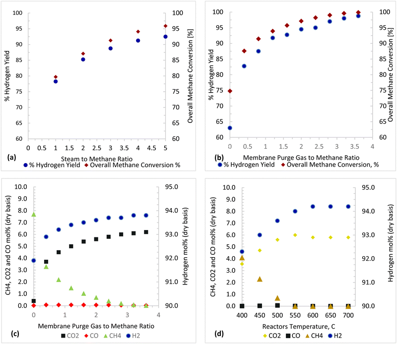 |
| | Fig. 13 Parametric investigation results (a) purge gas/CH4 = 2, reactor temperature: 500 °C (b) and (c) S/C = 3.75, reactor temperature: 500 °C, and (d) purge gas/CH4 = 2, S/C = 3.75. | |
Table 6 Summary of the results comparing baseline plant data and the novel ISEAM process
| Description |
Operating temperature, °C |
Net heating utility, MJ s−1 |
Total thermal energy input, MJ s−1 |
Total thermal energy output, MJ s−1 |
| Baseline SMR plant ref. 49 |
870 |
20.1 |
97.04 |
81.69 |
| Novel ISEAM process |
500 |
0 |
108.6 |
105.9 |
3.5 Economic analysis
The results of the economic model for the baseline SMR process and novel process are summarised in Tables 7, 8 and Fig. 14–16. The ISEAM process produced 2985 kg h−1 of product hydrogen which is approximately 27.2% higher when compared with the baseline SMR process, because of the higher hydrogen production efficiency using the same feed flowrate. As shown in Table 7 and Fig. 14, the total capital cost (TCR) for the baseline SMR is 32.4% higher than the ISEAM process, the first year operating cost (OPEX) for baseline SMR is approx 27% higher than that for the ISEAM process. The levelised cost of hydrogen (LCOH) was calculated as $2.6 per kg-H2 for the baseline SMR plant compared with $1.6 per kg-H2 for the novel ISEAM process (37.5% cost reduction in favor of the novel process). The novel ISEAM process was further optimised by operating the process units under optimal conditions as per Fig. 13(a) to (d) (S/C = 3.75, reactor temp. = 550 °C, purge gas/C1 ratio = 2), which increased the hydrogen production efficiency further (99.9%) giving a calculated LCOH of $1.3 per kg-H2, (50% cost reduction). Fig. 16 shows that the total cost requirement (TCR), commonly referred to as the capitalised cost (CAPEX), which constitutes between 44% and 46% of the LCOH for the three processes, followed by the variable operating and maintenance cost (VOM) which is between 30% and −32% of the LCOH. Sensitivity analysis on the effect of different fuel costs on the LCOH was carried out as shown in Fig. 15 and this effect is minimal. The cost of CO2 Removal (CCR) was calculated as $180 per tonneCO2 for the baseline SMR process compared with $76.5 per tonneCO2 for the baseline SMR plant operating with similar feed flowrates (which is a 57.5% cost reduction) in favor of the novel process. The optimized novel process has a Cost of CO2 Removal (CCR) of $33.2 per tonneCO2 (81.6% cost reduction compared to the baseline).
Table 7 Main results for economic analysis
| Equipment |
Baseline SMR |
Novel ISEAM process |
Optimised novel process |
| Total bare equipment cost (BEC), $1000 |
86![[thin space (1/6-em)]](https://www.rsc.org/images/entities/char_2009.gif) 494 494 |
63![[thin space (1/6-em)]](https://www.rsc.org/images/entities/char_2009.gif) 024 024 |
79![[thin space (1/6-em)]](https://www.rsc.org/images/entities/char_2009.gif) 568 568 |
| Total EPCC, $1000 |
6918.5 |
5042 |
6365 |
| Total process contingency, $1000 |
14![[thin space (1/6-em)]](https://www.rsc.org/images/entities/char_2009.gif) 930 930 |
13![[thin space (1/6-em)]](https://www.rsc.org/images/entities/char_2009.gif) 934.9 934.9 |
17![[thin space (1/6-em)]](https://www.rsc.org/images/entities/char_2009.gif) 433.8 433.8 |
| Total project contingency, $1000 |
10![[thin space (1/6-em)]](https://www.rsc.org/images/entities/char_2009.gif) 684 684 |
8100 |
10![[thin space (1/6-em)]](https://www.rsc.org/images/entities/char_2009.gif) 337 337 |
| Balance of plant (BOP), $1000 |
14![[thin space (1/6-em)]](https://www.rsc.org/images/entities/char_2009.gif) 577 577 |
10![[thin space (1/6-em)]](https://www.rsc.org/images/entities/char_2009.gif) 779 779 |
14![[thin space (1/6-em)]](https://www.rsc.org/images/entities/char_2009.gif) 486 486 |
| Total plant cost (TPC), $1000 |
133![[thin space (1/6-em)]](https://www.rsc.org/images/entities/char_2009.gif) 603.5 603.5 |
100![[thin space (1/6-em)]](https://www.rsc.org/images/entities/char_2009.gif) 880 880 |
128![[thin space (1/6-em)]](https://www.rsc.org/images/entities/char_2009.gif) 190 190 |
| Owner's cost, $1000 |
26![[thin space (1/6-em)]](https://www.rsc.org/images/entities/char_2009.gif) 988 988 |
20![[thin space (1/6-em)]](https://www.rsc.org/images/entities/char_2009.gif) 378 378 |
25![[thin space (1/6-em)]](https://www.rsc.org/images/entities/char_2009.gif) 894 894 |
| Total overnight cost (TOC), $1000 |
160![[thin space (1/6-em)]](https://www.rsc.org/images/entities/char_2009.gif) 591.5 591.5 |
121![[thin space (1/6-em)]](https://www.rsc.org/images/entities/char_2009.gif) 258 258 |
154![[thin space (1/6-em)]](https://www.rsc.org/images/entities/char_2009.gif) 084 084 |
| Total capital requirement (TCR) or (CAPEX) |
183![[thin space (1/6-em)]](https://www.rsc.org/images/entities/char_2009.gif) 074 074 |
138![[thin space (1/6-em)]](https://www.rsc.org/images/entities/char_2009.gif) 234 234 |
175![[thin space (1/6-em)]](https://www.rsc.org/images/entities/char_2009.gif) 656 656 |
| First ear OPEX |
26![[thin space (1/6-em)]](https://www.rsc.org/images/entities/char_2009.gif) 766 766 |
21![[thin space (1/6-em)]](https://www.rsc.org/images/entities/char_2009.gif) 082 082 |
26![[thin space (1/6-em)]](https://www.rsc.org/images/entities/char_2009.gif) 443 443 |
| Total hydrogen produced, kg h−1 |
2346 |
2985 |
4402 |
| First year LCOH |
$2.6 per kg-H2 |
$1.6 per kg-H2 |
$1.3 per kg-H2 |
| Cost of CO2 avoided (CCA) $ per tonneCO2 (zero tax credit) |
$188 per tonneCO2 |
$65.2 per tonneCO2 |
$28.2 per tonneCO2 |
| Cost of CO2 Removal (CCR) $ per tonneCO2 (zero tax credit) |
$180 per tonneCO2 |
$76.5 per tonneCO2 |
$33.2 per tonneCO2 |
Table 8 Bare equipment cost results for economic analysis
| Equipment |
Baseline SMR |
Novel ISEAM process |
Optimised novel process |
| Equipment |
BEC, $1000 |
BEC, $1000 |
BEC, $1000 |
| Feed to plant |
315 kmol h−1 natural gas |
315 kmol h−1 natural gas |
500 kmol h−1 natural gas |
|
|
909 kmol h−1 steam |
909 kmol h−1 steam |
1875 kmol h−1 steam |
| Hydrogen produced |
23.4 MMSCFD (2346 kg h−1) |
29.7 MMSCFD (2985 kg h−1) |
43.8 MMSCFD (4,402 kg h−1) |
| SMR Reactor |
17![[thin space (1/6-em)]](https://www.rsc.org/images/entities/char_2009.gif) 589 589 |
— |
— |
| Sulfur polisher (ZnO) |
73.895 |
85.26 |
107.6 |
| Primary air compressor |
2018 |
1699 |
2145 |
| Water gas shift reactor |
3928 |
— |
— |
| MDEA CO2 unit (95% CO2 removal) |
25![[thin space (1/6-em)]](https://www.rsc.org/images/entities/char_2009.gif) 541 541 |
— |
— |
| MEA CO2 unit (90% CO2) removal |
24![[thin space (1/6-em)]](https://www.rsc.org/images/entities/char_2009.gif) 228 228 |
— |
— |
| PSA unit |
11![[thin space (1/6-em)]](https://www.rsc.org/images/entities/char_2009.gif) 570 570 |
13![[thin space (1/6-em)]](https://www.rsc.org/images/entities/char_2009.gif) 349 349 |
16![[thin space (1/6-em)]](https://www.rsc.org/images/entities/char_2009.gif) 853 853 |
| Boiler package |
1546 |
1861 |
2349.5 |
| Carbonator reactor |
— |
40![[thin space (1/6-em)]](https://www.rsc.org/images/entities/char_2009.gif) 773 773 |
51475.8 |
| Membrane reactor |
— |
5257 |
6637 |
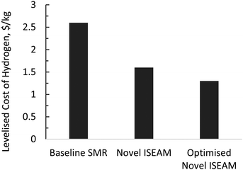 |
| | Fig. 14 Levelized cost of hydrogen comparison between baseline SMR process and novel ISEAM process at different fuel cost. | |
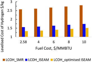 |
| | Fig. 15 Economic evaluation comparison at different fuel cost. | |
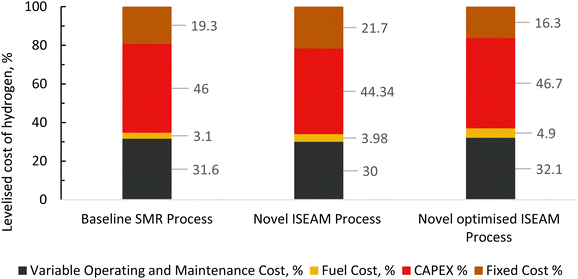 |
| | Fig. 16 Distribution of different components of levelized cost (%) for the baseline SMR Process, novel ISEAM and optimised ISEAM process at a fuel cost of $2.58/MMBTU. | |
4. Conclusions
A novel blue hydrogen process, the Industrial Sorption Enhanced Auto-Thermal Membrane (ISEAM) process has been developed, modelled, and validated using experimental data from the literature and with thermodynamic equilibrium data. The novel process was benchmarked against a baseline Industrial Steam Methane Reforming plant using the same feed compositions and flowrate. The novel process shows improvements in methane conversion, and a hydrogen yield of over 32%. The novel process thermal efficiency of 97.5% (41% higher than the baseline process) is among the highest compared with alternative processes. Pinch analysis on the novel process shows that the process is auto thermal (no external heating required). Economic evaluation shows a levelized cost of hydrogen (LCOH) of $1.6 per kg-H2 and the cost of CO2 removal (CCR) of $76.5 per tonneCO2 for the novel ISEAM process compared to a LCOH of $2.6 per kg-H2 and the cost of CO2 removal (CCR) of $180 per tonneCO2 for the baseline SMR plant operating with similar feed flowrates. The optimized novel ISEAM process (at a higher feed rate and higher hydrogen production) gives a LCOH of $1.3 per kg-H2 and a cost of CO2 removal (CCR) of $33.2 per tonneCO2. Hydrogen permeation was identified as being as important as hydrogen selectivity in the design of the Membrane Reactor as more than an average of 54.5% of produced hydrogen was required to be removed from the reactor reaction zones to break the thermochemical reversible equilibrium constraints and shift the reforming reactions to the forward direction. The amounts of CO leaving the reactors were reduced to ppm levels. Parametric equilibrium investigations on the novel ISEAM process show that a higher steam-to-methane molar ratio, higher membrane reactor purge gas-to-methane molar ratio, and a higher reactor temperature all increase the methane conversion and hydrogen yield. Optimal operating parameters for the novel ISEAM process were identified. The novel ISEAM process eliminates some of the issues associated with the baseline SMR process such as thermodynamic equilibrium constraints, large amount of utility fuel usage and the use of additional unit operations such as an amine unit to capture the produced CO2. In addition, steady state operation can be maintained by automating the switching between the sorption/calcination process of the Carbonator-SMR Reactor. The novel ISEAM base process uses a palladium-alloy catalytic membrane reactor and CaO-based Carbonator-SMR Reactor. The capture capacities of CaO-based sorbents are known to decrease rapidly during cycles of carbonation/calcination due to sintering and attrition. Various research works ranging from doping, thermal-pre-treatment, incorporation of inert supports and chemical treatment are being carried out to address the issue of reduced sorption capacity including the use of alternative sorbents such as hydrotalcite. The use of other high temperature membranes such as silica, zeolite, etc, are also being researched. The novel ISEAM process is adaptable and will be able to use such new materials in the future.
Conflicts of interest
There are no conflicts to declare.
Appendix A
Table 9 Experimental data used for carbonator-SMR reactor model validation62
| Description |
Value |
| Methane flowrate, NL/h |
11.2 |
| Steam: methane ratio |
3 |
| Reactor temperature, °C |
700 |
| Reactor pressure, kPa |
300 |
| GHSV, h−1 |
341.5 |
| Bed void fraction |
0.5 |
| CaO density, kg m−3 |
1257 |
| Reactor diameter, m |
0.024 |
| Reactor length, m |
0.29 |
Table 10 Experimental data used for membrane reactor model validation44
| Parameters |
Values |
Units |
| Membrane diameter |
0.0127 |
m |
| Length of membrane tube |
0.25 |
m |
| Membrane thickness |
6 |
μm |
| Methane feed flow |
0.78 |
mol h−1 |
| Membrane sweep gas flowrate |
0.5 |
mol h−1 |
| Reactor pressure |
350 |
kPa |
| Reactor temperature |
500 |
°C |
| Retentate pressure |
100 |
kPa |
| Membrane permeance |
0.00346 |
mol m−2 s−1 Pa0.5 |
Appendix B
Table 11 Rate and kinetic equations for the main reactions
| Reactions |
Rate equations |
Kinetic equation and constants |
Ref. |

|

|
(10) |
k
1 = 1.17 × 10¹²![[thin space (1/6-em)]](https://www.rsc.org/images/entities/char_2009.gif) exp(−240 exp(−240![[thin space (1/6-em)]](https://www.rsc.org/images/entities/char_2009.gif) 100/RT) 100/RT) |
(13) |
4,40,51,52
|

|

|
(11) |
k
2 = 5.42 × 10¹²![[thin space (1/6-em)]](https://www.rsc.org/images/entities/char_2009.gif) exp(67 exp(67![[thin space (1/6-em)]](https://www.rsc.org/images/entities/char_2009.gif) 130/RT) 130/RT) |
(14) |
4,40,51,52
|

|

|
(12) |
k
3 = 2.83 × 10¹¹![[thin space (1/6-em)]](https://www.rsc.org/images/entities/char_2009.gif) exp(−243 exp(−243![[thin space (1/6-em)]](https://www.rsc.org/images/entities/char_2009.gif) 900/RT) 900/RT) |
(15) |
4,40,51,52
|
|
|

|
(16) |
4,40,51,52
|
k
CH4 = 6.65 × 10⁻⁴![[thin space (1/6-em)]](https://www.rsc.org/images/entities/char_2009.gif) exp(38 exp(38![[thin space (1/6-em)]](https://www.rsc.org/images/entities/char_2009.gif) 280/RT) 280/RT) |
(17) |
4,40,51,52
|
k
H2O = 1.77 × 10⁵![[thin space (1/6-em)]](https://www.rsc.org/images/entities/char_2009.gif) exp(−88 exp(−88![[thin space (1/6-em)]](https://www.rsc.org/images/entities/char_2009.gif) 680/RT) 680/RT) |
(18) |
4,40,51,52
|
k
CO = 8.25 × 10⁻⁵![[thin space (1/6-em)]](https://www.rsc.org/images/entities/char_2009.gif) exp(70 exp(70![[thin space (1/6-em)]](https://www.rsc.org/images/entities/char_2009.gif) 650/RT) 650/RT) |
(19) |
4,40,51,52
|
k
H2 = 6.15 × 10⁻⁹![[thin space (1/6-em)]](https://www.rsc.org/images/entities/char_2009.gif) exp(82 exp(82![[thin space (1/6-em)]](https://www.rsc.org/images/entities/char_2009.gif) 900/RT) 900/RT) |
(20) |
4,40,51,52
|
k
1 = 4.71 × 10¹²![[thin space (1/6-em)]](https://www.rsc.org/images/entities/char_2009.gif) exp(−224 exp(−224![[thin space (1/6-em)]](https://www.rsc.org/images/entities/char_2009.gif) 000/RT) 000/RT) |
(21) |
4,40,51,52
|
k
2 = 1.14 × 10⁻¹²![[thin space (1/6-em)]](https://www.rsc.org/images/entities/char_2009.gif) exp(37 exp(37![[thin space (1/6-em)]](https://www.rsc.org/images/entities/char_2009.gif) 300/RT) 300/RT) |
(22) |
4,40,51,52
|
|
K
3 = K1K2 |
(23) |
4,40,51,52
|
|
|

|

|
(24) |
40,53
|
|
k
reac-max = 0.36 s−1 |
(25) |
40,53
|

|
(26) |
40,53
|
The hydrogen flow from the retentate to the permeate side of the membrane reactor is governed by Sievert's law:  |
(27) |
40,44
|
Notes and references
- US Energy Information Administration, dated 13th April, 2021.
- Hydrogen scaling up. A sustainable pathway for the global energy transition, Hydrogen Council (dated 2017), (http://www.hydrogencouncil.com/wpcontent/uploads/2017/11/hydrogen-scaling-up-hydrogencouncil.pdf).
- D. Celik and M. Yildiz, Investigation of hydrogen production methods in accordance with green chemistry principles, Int. J. Hydrogen Energy, 2017, 42(36), 23395–23401 CrossRef CAS.
- H. Lee, B. Lee, M. Byun and H. Lim, Comparative techno-economic analysis for steam methane reforming in a sorption-enhanced membrane reactor: Simultaneous H2 production and CO2 capture, Chem. Eng. Res. Des., 2021, 171, 383–394 CrossRef CAS.
- Y. Yan, V. Manovic, E. J. Anthony and P. T. Clough, Techno-economic analysis of low-carbon hydrogen production by sorption enhanced steam methane reforming (SE-SMR) processes, Energy Convers. Manage., 2020, 226, 113530 CrossRef CAS.
- P. Nikolaidis and A. Poullikkas, A comparative overview of hydrogen production processes, Renewable Sustainable Energy Rev., 2017, 67, 597–611 CrossRef CAS.
- L. Zhu, L. Li and J. Fan, A modified process for overcoming the drawbacks of conventional steam methane reforming for hydrogen production: Thermodynamic investigation, Chem. Eng. Res. Des., 2015, 104, 792–806 CrossRef CAS.
- Y. Ma, G. Guan, X. Hao, J. Cao and A. Abudula, Molybdenum carbide as alternative catalyst for hydrogen production – A review, Renewable Sustainable Energy Rev., 2017, 75, 1101–1129 CrossRef CAS.
- C.-H. Chen, C.-T. Yu and W.-H. Chen, Improvement of steam methane reforming via in-situ CO2 sorption over a nickel-calcium composite catalyst, Int. J. Hydrogen Energy, 2021, 46(31), 16655–16666 CrossRef CAS.
- A. Di Giuliano and K. Gallucci, Sorption enhanced steam methane reforming based on nickel and calcium looping: a review, Chem. Eng. Process., 2018, 130, 240–252 CrossRef CAS.
- S. Z. Abbas, V. Dupont and T. Mahmud, Modelling of high purity H2 production via sorption enhanced chemical looping steam reforming of methane in a packed bed reactor, Fuel (Guildford), 2017, 202, 271–286 CrossRef CAS.
- A. Phuluanglue, W. Khaodee and S. Assabumrungrat, Simulation of intensified process of sorption enhanced chemical-looping reforming of methane: Comparison with conventional processes, Comput. Chem. Eng., 2017, 105, 237–245 CrossRef CAS.
- S. Abuelgasim, W. Wang and A. Abdalazeez, A brief review for chemical looping combustion as a promising CO2 capture technology: Fundamentals and progress, Sci. Total Environ, 2021, 764, 142892 CrossRef CAS PubMed.
- S. Z. Abbas, V. Dupont and T. Mahmud, Modelling of H2 production in a packed bed reactor via sorption enhanced steam methane reforming process, Int. J. Hydrogen Energy, 2017, 42(30), 18910–18921 CrossRef CAS.
- J. R. Fernandez, J. C. Abanades and R. Murillo, Modeling of sorption enhanced steam methane reforming in an adiabatic fixed bed reactor, Chem. Eng. Sci., 2012, 84, 1–11 CrossRef CAS.
- J. R. Fernandez, J. C. Abanades and G. Grasa, Modeling of sorption enhanced steam methane reforming—Part II: Simulation within a novel Ca/Cu chemical loop process for hydrogen production, Chem. Eng. Sci., 2012, 84, 12–20 CrossRef CAS.
- G. Ji, J. G. Yao, P. T. Clough, J. C. D. da Costa, E. J. Anthony and P. S. Fennell,
et al., Enhanced hydrogen production from thermochemical processes, Energy Environ. Sci., 2018, 11(1), 2647–2672 RSC.
- M. Broda, V. Manovic, Q. Imtiaz, A. M. Kierzkowska, E. J. Anthony and C. R. Müller, High-Purity Hydrogen via the Sorption-Enhanced Steam Methane Reforming Reaction over a Synthetic CaO-Based Sorbent and a Ni Catalyst, Environ. Sci. Technol., 2013, 47(11), 6007–6014 CrossRef CAS PubMed.
- J. R. Fernández and J. C. Abanades, Sorption enhanced reforming of methane combined with an iron oxide chemical loop for the production of hydrogen with CO2 capture: Conceptual design and operation strategy, Appl. Therm. Eng., 2017, 125, 811–822 CrossRef.
- M. Erans, V. Manovic and E. J. Anthony, Calcium looping sorbents for CO2 capture, Appl. Energy, 2016, 180, 722–742 CrossRef CAS.
- B. Dou, Y. Song, Y. Liu and C. Feng, High temperature CO2 capture using calcium oxide sorbent in a fixed-bed reactor, J. Hazard. Mater., 2010, 183(1–3), 759–765 CrossRef CAS PubMed.
- I. Aloisi, A. Di Giuliano, A. Di Carlo, P. U. Foscolo, C. Courson and K. Gallucci, Sorption enhanced catalytic Steam Methane Reforming: Experimental data and simulations describing the behaviour of bi-functional particles, Chem. Eng. J., 2017, 314, 570–582 CrossRef CAS.
- I. Aloisi, N. Jand, S. Stendardo and P. U. Foscolo, Hydrogen by sorption enhanced methane reforming: A grain model to study the behavior of bi-functional sorbent-catalyst particles, Chem. Eng. Sci., 2016, 149, 22–34 CrossRef CAS.
- J. Adanez, A. Abad, F. Garcia-Labiano, P. Gayan and L. F. de Diego, Progress in Chemical-Looping Combustion and Reforming technologies, Prog. Energy Combust. Sci., 2012, 38(2), 215–282 CrossRef CAS.
- J. Boon, V. Spallina, Y. van Delft and M. van Sint Annaland, Comparison of the efficiency of carbon dioxide capture by sorption-enhanced water-gas shift and palladium-based membranes for power and hydrogen production, Int. J. Greenhouse Gas Control, 2016, 50, 121–134 CrossRef CAS.
- F. H. Alshafei, L. T. Minardi, D. Rosales, G. Chen and A. Simonetti Dante, Improved Sorption-Enhanced Steam Methane Reforming via Calcium Oxide–Based Sorbents with Targeted Morphology, Energy Technol., 2019, 7(3), 1800807 CrossRef.
- H. Yu, H. Sun, G. Bao, H. Liu, J. Hu and H. Wang, Computational fluid dynamics study of hydrogen production by sorption enhanced steam ethanol reforming process in fluidized bed, Fuel (Guildford), 2023, 344, 128043 CrossRef CAS.
- C. Udemu and C. Font-Palma, Modelling of sorption-enhanced steam reforming (SE-SR) process in fluidised bed reactors for low-carbon hydrogen production: A review, Fuel (Guildford), 2023, 340, 127588 CrossRef CAS.
- A. Mostafa, I. Rapone, A. Bosetti, M. C. Romano, A. Beretta and G. Groppi, Modelling of methane sorption enhanced reforming for blue hydrogen production in an adiabatic fixed bed reactor: unravelling the role of the reactor’s thermal behavior, Int. J. Hydrogen Energy, 2023, 48, 26475–26491 CrossRef CAS.
- B. Lee and H. Lim, Cost-competitive methane steam reforming in a membrane reactor for H2 production: Technical and economic evaluation with a window of a H2 selectivity, Int. J. Energy Res., 2019, 43(4), 1468–1478 CrossRef CAS.
- A. Iulianelli, S. Liguori, J. Wilcox and A. Basile, Advances on methane steam reforming to produce hydrogen through membrane reactors technology: A review, Catal. Rev.: Sci. Eng., 2016, 58(1), 1–35 CrossRef CAS.
- X. Wu, C. Wu and S. Wu, Dual-enhanced steam methane reforming by membrane separation of H2 and reactive sorption of CO2, Chem. Eng. Res. Des., 2015, 96, 150–157 CrossRef CAS.
- M. A. Murmura, S. Cerbelli and M. C. Annesini, An equilibrium theory for catalytic steam reforming in membrane reactors, Chem. Eng. Sci., 2017, 160, 291–303 CrossRef CAS.
- H. Lee, A. Kim, B. Lee and H. Lim, Comparative numerical analysis for an efficient hydrogen production via a steam methane reforming with a packed-bed reactor, a membrane reactor, and a sorption-enhanced membrane reactor, Energy Convers. Manage., 2020, 213, 112839 CrossRef CAS.
- K. Ghasemzadeh, R. Zeynali, A. Basile and A. Iulianelli, CFD analysis of a hybrid sorption-enhanced membrane reactor for hydrogen production during WGS reaction, Int. J. Hydrogen Energy, 2017, 42(43), 26914–26923 CrossRef CAS.
- J. M. Alarcón, J. R. Fernández and J. C. Abanades, Study of a Cu-CuO chemical loop for the calcination of CaCO3 in a fixed bed reactor, Chem. Eng. J., 2017, 325, 208–220 CrossRef.
- J. R. Fernández and J. C. Abanades, Overview of the Ca–Cu looping process for hydrogen production and/or power generation, Curr. Opin. Chem. Eng., 2017, 17, 1–8 CrossRef.
- J. C. Abanades, R. Murillo, J. R. Fernandez, G. Grasa and I. Martínez, New CO2 Capture Process for Hydrogen Production Combining Ca and Cu Chemical Loops, Environ. Sci. Technol., 2010, 44(17), 6901–6904 CrossRef CAS PubMed.
- L. Díez-Martín, I. Martínez, G. Grasa and R. Murillo, Investigation of the reduction kinetics of high loaded CuO-based materials suitable for the Ca/Cu looping process, Fuel (Guildford), 2018, 230, 376–389 CrossRef.
- M. M. Shahid, S. Z. Abbas, F. Maqbool, S. Ramirez-Solis, V. Dupont and T. Mahmud, Modeling of sorption enhanced steam methane reforming in an adiabatic packed bed reactor using various CO2 sorbents, J. Environ. Chem. Eng., 2021, 9(5), 105863 CrossRef CAS.
- G. Diglio, D. P. Hanak, P. Bareschino, F. Pepe, F. Montagnaro and V. Manovic, Modelling of sorption-enhanced steam methane reforming in a fixed bed reactor network integrated with fuel cell, Appl. Energy, 2018, 210, 1–15 CrossRef CAS.
- S. M. Nazir, J. H. Cloete, S. Cloete and S. Amini, Pathways to low-cost clean hydrogen production with gas switching reforming, Int. J. Hydrogen Energy, 2021, 46(38), 20142–20158 CrossRef CAS.
- J. D. Silva and C. A. M. de Abreu, Modelling and simulation in conventional fixed-bed and fixed-bed membrane reactors for the steam reforming of methane, Int. J. Hydrogen Energy, 2016, 41(27), 11660–11674 CrossRef CAS.
- C.-H. Kim, J.-Y. Han, H. Lim, D.-W. Kim and S.-K. Ryi, Methane steam reforming in a membrane reactor using high-permeable and low-selective Pd-Ru membrane, Korean J. Chem. Eng., 2017, 34(4), 1260–1265 CrossRef CAS.
- G. Ye, D. Xie, W. Qiao, J. R. Grace and C. J. Lim, Modeling of fluidized bed membrane reactors for hydrogen production from steam methane reforming with Aspen Plus, Int. J. Hydrogen Energy, 2009, 34(11), 4755–4762 CrossRef CAS.
- A. Shafiee, M. Arab, Z. Lai, Z. Liu and A. Abbas, Modelling and sequential simulation of multi-tubular metallic membrane and techno-economics of a hydrogen production process employing thin-layer membrane reactor, Int. J. Hydrogen Energy, 2016, 41(42), 19081–19097 CrossRef CAS.
- G. Ji, M. Zhao and G. Wang, Computational fluid dynamic simulation of a sorption-enhanced palladium membrane reactor for enhancing hydrogen production from methane steam reforming, Energy (Oxford), 2018, 147, 884–895 CrossRef CAS.
- B. Dou, K. Wu, H. Zhang, B. Chen, H. Chen and Y. Xu, Sorption-enhanced chemical looping steam reforming of glycerol with CO2 in-situ capture and utilization, Chem. Eng. J., 2023, 452, 139703 CrossRef CAS.
- M. Salem, A. M. Shoaib and A. F. M. Ibrahim, Simulation of a Natural Gas Steam Reforming Plant for Hydrogen Production Optimization, Chem. Eng. Technol., 2021, 44(9), 1651–1659 CrossRef CAS.
- M. Salem, A. M. Shoaib and A. F. M. Ibrahim, Simulation of a Natural Gas Steam Reforming Plant for Hydrogen Production Optimization, Chem. Eng. Technol., 2021, 44(9), 1651–1659 CrossRef CAS.
- W.-J. Sheu, C.-Y. Chang and Y.-C. Chen, Transient reaction phenomena of sorption-enhanced steam methane reforming in a fixed-bed reactor, Int. J. Hydrogen Energy, 2022, 47(7), 4357–4374 CrossRef CAS.
- J. Xu and G. F. Froment, Methane steam reforming, methanation and water-gas shift: I. Intrinsic kinetics, AIChE J., 1989, 35(1), 88–96 CrossRef CAS.
- N. Rodríguez, M. Alonso and J. C. Abanades, Experimental investigation of a circulating fluidized-bed reactor to capture CO2 with CaO, AIChE J., 2011, 57(5), 1356–1366 CrossRef.
- GCCSI. Global CCS Institute-toward a common method of cost estimation for CO2 capture and storage at fossil fuel power plants. 2013.
- Oxera. Discount rates for low-carbon and renewable generation technologies Prepared for the Committee on Climate Change. 2011.
- M. N. Khan and T. Shamim, Techno-economic assessment of a plant based on a three reactor chemical looping reforming system, Int. J. Hydrogen Energy, 2016, 41(48), 22677–22688 CrossRef CAS.
- G. Collodi, G. Azzaro, N. Ferrari and S. Santos, Techno-economic Evaluation of Deploying CCS in SMR Based Merchant H2 Production with NG as Feedstock and Fuel, Energy Procedia, 2017, 114, 2690–2712 CrossRef CAS.
-
E. Callum, et al., Novel Steam Methane/Gas Heated Reformer Phase 1 Final Study Report, Wood Group UK Limited: UK, 2020, p. 22.
-
M. Haaf, R. Anantharaman, S. Roussanaly, J. Ströhle and B. Epple CO2 capture from waste-to-energy plants: Techno-economic assessment of novel integration concepts of calcium looping technology. 2020.
- National Energy Technology Laboratory, Assessment of hydrogen Production with CO2 Capture Volume 1: Baseline-State-Of the-Arts Plant, Revision 1, Nov 14th, 2011, DOE/NETL-2011/1434.
- Department for Business Energy & Industrial Strategy, Hydrogen Production Costs, 2021.
- D. K. Lee, I. H. Baek and W. L. Yoon, Modeling and simulation for the methane steam reforming enhanced by in situ CO2 removal utilizing the CaO carbonation for H2 production, Chem. Eng. Sci., 2004, 59(4), 931–942 CrossRef CAS.
- H. Bahzad, N. Shah, N. M. Dowell, M. Boot-Handford, S. M. Soltani and M. Ho,
et al., Development and techno-economic analyses of a novel hydrogen production process via chemical looping, Int. J. Hydrogen Energy, 2019, 44(39), 21251–21263 CrossRef CAS.
- S. Z. Abbas, V. Dupont and T. Mahmud, Kinetics study and modelling of steam methane reforming process over a NiO/Al2O3 catalyst in an adiabatic packed bed reactor, Int. J. Hydrogen Energy, 2017, 42(5), 2889–2903 CrossRef CAS.
|
| This journal is © The Royal Society of Chemistry 2023 |
 Open Access Article
 ab,
Paul S.
Fennell
a,
Christopher J.
Tighe
a and
Ahmed Al
Dawood
 b
b


![[thin space (1/6-em)]](https://www.rsc.org/images/entities/char_2009.gif) 841
841![[thin space (1/6-em)]](https://www.rsc.org/images/entities/char_2009.gif) 918
918![[thin space (1/6-em)]](https://www.rsc.org/images/entities/char_2009.gif) 985
985![[thin space (1/6-em)]](https://www.rsc.org/images/entities/char_2009.gif) 176
176![[thin space (1/6-em)]](https://www.rsc.org/images/entities/char_2009.gif) 047
047


 , the reactor temperature initially increased to a maximum value of 595 °C within the first 1 m of the reactor length, resulting in faster initial kinetics. The reaction rates become slow afterward as the endothermic reforming dominates. The hydrogen molar fraction rises quickly initially from 19.4% (dry basis) close to the reactor inlet and continues to increase slowly along the reactor length, leaving the Carbonator-SMR reactor at 87% (dry basis). The methane molar fraction drops very quickly initially from 69.5% (dry basis) close to the reactor inlet and continues to decrease slowly along the reactor length, leaving the reactor at 12.7% (dry basis). Fig. 12 shows the Membrane Reactor performance; the reforming and water gas shift reactions are at the slowest rate between the membrane reactor length of 0–8 meters because of the high molar flowrate of hydrogen within these reaction zones (22–87%). The permeation of hydrogen is however at the highest at these locations because of a higher retentate hydrogen partial pressure. As more hydrogen is removed in situ from the reaction zones along the membrane reactor, this leads to more methane conversion (and a reduction of methane molar flowrate) and more hydrogen production as per Le-Chatelier's principle. Hydrogen permeation is identified as being as critical as hydrogen selectivity in the design of the Membrane Reactor as more than an average of 54.5% of produced hydrogen was required to be removed from the reactor reaction zones to break the thermochemical reversible equilibrium constraints and shift the reforming reactions to the forward direction.


 is endothermic and is favored by high temperature, as shown in Fig. 13(d). For a Carbonator-SMR Reactor and Membrane SMR Reactor temperature of 550 °C, the process achieves the maximum methane conversion and hydrogen yield of 99.9% Table 6.

![[thin space (1/6-em)]](https://www.rsc.org/images/entities/char_2009.gif) 494
494![[thin space (1/6-em)]](https://www.rsc.org/images/entities/char_2009.gif) 024
024![[thin space (1/6-em)]](https://www.rsc.org/images/entities/char_2009.gif) 568
568![[thin space (1/6-em)]](https://www.rsc.org/images/entities/char_2009.gif) 930
930![[thin space (1/6-em)]](https://www.rsc.org/images/entities/char_2009.gif) 934.9
934.9![[thin space (1/6-em)]](https://www.rsc.org/images/entities/char_2009.gif) 433.8
433.8![[thin space (1/6-em)]](https://www.rsc.org/images/entities/char_2009.gif) 684
684![[thin space (1/6-em)]](https://www.rsc.org/images/entities/char_2009.gif) 337
337![[thin space (1/6-em)]](https://www.rsc.org/images/entities/char_2009.gif) 577
577![[thin space (1/6-em)]](https://www.rsc.org/images/entities/char_2009.gif) 779
779![[thin space (1/6-em)]](https://www.rsc.org/images/entities/char_2009.gif) 486
486![[thin space (1/6-em)]](https://www.rsc.org/images/entities/char_2009.gif) 603.5
603.5![[thin space (1/6-em)]](https://www.rsc.org/images/entities/char_2009.gif) 880
880![[thin space (1/6-em)]](https://www.rsc.org/images/entities/char_2009.gif) 190
190![[thin space (1/6-em)]](https://www.rsc.org/images/entities/char_2009.gif) 988
988![[thin space (1/6-em)]](https://www.rsc.org/images/entities/char_2009.gif) 378
378![[thin space (1/6-em)]](https://www.rsc.org/images/entities/char_2009.gif) 894
894![[thin space (1/6-em)]](https://www.rsc.org/images/entities/char_2009.gif) 591.5
591.5![[thin space (1/6-em)]](https://www.rsc.org/images/entities/char_2009.gif) 258
258![[thin space (1/6-em)]](https://www.rsc.org/images/entities/char_2009.gif) 084
084![[thin space (1/6-em)]](https://www.rsc.org/images/entities/char_2009.gif) 074
074![[thin space (1/6-em)]](https://www.rsc.org/images/entities/char_2009.gif) 234
234![[thin space (1/6-em)]](https://www.rsc.org/images/entities/char_2009.gif) 656
656![[thin space (1/6-em)]](https://www.rsc.org/images/entities/char_2009.gif) 766
766![[thin space (1/6-em)]](https://www.rsc.org/images/entities/char_2009.gif) 082
082![[thin space (1/6-em)]](https://www.rsc.org/images/entities/char_2009.gif) 443
443![[thin space (1/6-em)]](https://www.rsc.org/images/entities/char_2009.gif) 589
589![[thin space (1/6-em)]](https://www.rsc.org/images/entities/char_2009.gif) 541
541![[thin space (1/6-em)]](https://www.rsc.org/images/entities/char_2009.gif) 228
228![[thin space (1/6-em)]](https://www.rsc.org/images/entities/char_2009.gif) 570
570![[thin space (1/6-em)]](https://www.rsc.org/images/entities/char_2009.gif) 349
349![[thin space (1/6-em)]](https://www.rsc.org/images/entities/char_2009.gif) 853
853![[thin space (1/6-em)]](https://www.rsc.org/images/entities/char_2009.gif) 773
773


![[thin space (1/6-em)]](https://www.rsc.org/images/entities/char_2009.gif) exp(−240
exp(−240![[thin space (1/6-em)]](https://www.rsc.org/images/entities/char_2009.gif) 100/RT)
100/RT)

![[thin space (1/6-em)]](https://www.rsc.org/images/entities/char_2009.gif) exp(67
exp(67![[thin space (1/6-em)]](https://www.rsc.org/images/entities/char_2009.gif) 130/RT)
130/RT)

![[thin space (1/6-em)]](https://www.rsc.org/images/entities/char_2009.gif) exp(−243
exp(−243![[thin space (1/6-em)]](https://www.rsc.org/images/entities/char_2009.gif) 900/RT)
900/RT)
![[thin space (1/6-em)]](https://www.rsc.org/images/entities/char_2009.gif) exp(38
exp(38![[thin space (1/6-em)]](https://www.rsc.org/images/entities/char_2009.gif) 280/RT)
280/RT)![[thin space (1/6-em)]](https://www.rsc.org/images/entities/char_2009.gif) exp(−88
exp(−88![[thin space (1/6-em)]](https://www.rsc.org/images/entities/char_2009.gif) 680/RT)
680/RT)![[thin space (1/6-em)]](https://www.rsc.org/images/entities/char_2009.gif) exp(70
exp(70![[thin space (1/6-em)]](https://www.rsc.org/images/entities/char_2009.gif) 650/RT)
650/RT)![[thin space (1/6-em)]](https://www.rsc.org/images/entities/char_2009.gif) exp(82
exp(82![[thin space (1/6-em)]](https://www.rsc.org/images/entities/char_2009.gif) 900/RT)
900/RT)![[thin space (1/6-em)]](https://www.rsc.org/images/entities/char_2009.gif) exp(−224
exp(−224![[thin space (1/6-em)]](https://www.rsc.org/images/entities/char_2009.gif) 000/RT)
000/RT)![[thin space (1/6-em)]](https://www.rsc.org/images/entities/char_2009.gif) exp(37
exp(37![[thin space (1/6-em)]](https://www.rsc.org/images/entities/char_2009.gif) 300/RT)
300/RT)


