
 Open Access Article
 This Open Access Article is licensed under a
 Creative Commons Attribution 3.0 Unported Licence
Optimized design and techno-economic analysis of novel DME production processes†
Malte
Semmel
 ab,
Maximilian
Kerschbaum
a,
Benedikt
Steinbach
a,
Jörg
Sauer
b and
Ouda
Salem
*a
ab,
Maximilian
Kerschbaum
a,
Benedikt
Steinbach
a,
Jörg
Sauer
b and
Ouda
Salem
*a
aFraunhofer Institute for Solar Energy Systems ISE, Heidenhofstr. 2, 79110 Freiburg, Germany. E-mail: ouda.salem@ise.fraunhofer.de
bKarlsruhe Institute of Technology (KIT), Hermann-von-Helmholtz-Platz 1, D-76344 Eggenstein-Leopoldshafen, Germany
First published on 4th August 2023
Abstract
The shift from gas to liquid phase DME synthesis enables an intensified process concept towards efficient large scale DME production. In this work, four process concepts based on liquid phase DME synthesis were proposed and optimized. A comprehensive economic model was applied with the objective of minimizing the total production cost. All concepts were evaluated applying our previously validated reaction kinetics for commercial ion exchange resin selected catalysts. Furthermore, every process concept was studied with a pure MeOH feed and water-rich (crude) MeOH feedstock. The conventional gas-phase DME production process was simulated and evaluated using the same technical and economic parameters to serve as a benchmark. Using a chlorinated high temperature stable IER catalyst led to significant cost reduction in all the considered concepts. This was due to the higher reaction rate enabled by the higher operating temperature of this catalyst. In the integrated process concept with H2 and CO2 as sustainable feedstocks, it was shown that the reactive distillation process shows a 27% lower production cost, when the crude methanol is directly fed to the DME process instead of being purified in a dedicated crude methanol distillation column. A further techno-economic optimization can be achieved when complementing the reactive distillation column with an additional reactor. Overall, the process concept of a reactive distillation column with a side reactor presents the most promising process concept, enabling a 39% lower production cost than the conventional gas-phase process. By heat integration with a CO2-based MeOH plant, a DME production technology with no external heat demand and a net conversion cost of 54.4 € per tDME is possible.
Introduction
Hydrogen is a key element for the defossilisation of the energy economy.1,2 A large share of the hydrogen demand will be in industrial countries with limited potential for renewable energy generation, while economically attractive green hydrogen production is allocated at regions with high abundance of renewable energy resources. A promising strategy to solve this mismatch and to integrate the renewable energy potential from countries of the global south into the energy system of industrial countries lies in the efficient transport of hydrogen and its derivatives. Current forecasts predict a global hydrogen production capacity of 243–384 Mtpa by 2030 of which around 12 Mt of hydrogen will be traded.3Dimethyl ether (DME, CH3–O–CH3) is an excellent hydrogen carrier with 26 wt% technical H2 capacity (48% higher storage capacity than ammonia), environmentally benign properties and similar physiochemical properties to CO2. This could allow the establishment of a closed DME/CO2 cycle for sustainable global H2 transport at a large scale.5 With existing global production capacities of about 10 Mtpa, DME is an important methanol derivative. The major current use of DME is in blending with LPG. This sector demand alone is projected to reach an annual DME production of 40 Mt by 2050, a fourfold increase compared to the current global production capacities.6,7
Conventionally, DME is produced via the equilibrium-limited dehydration of pure MeOH in the gas phase and consecutive two-step distillation of the ternary MeOH–DME–H2O product mixture. Besides being a rather complex plant layout, this process implies a high energy demand, since the MeOH feedstock needs to be evaporated and heated up to the elevated DME reaction temperature above 275 °C.8 Furthermore, the conventional catalytic process is not capable of converting water-rich crude MeOH, thus requiring the purification of MeOH in a dedicated crude MeOH distillation column prior to the conversion to DME. An alternative process is the direct synthesis of DME from syngas. While the coupling of MeOH and DME synthesis entails the advantage of an increased CO2 conversion, the downstream processing in this process is more complex as the presence of DME in the reactor product hampers the separation and recycling of syngas. Furthermore, for CO2-rich syngas, the process is thermodynamically inhibited due to strong water production.9,10
Liquid phase DME synthesis presents a promising technological alternative since it allows the omission of the methanol (MeOH) evaporation step and thus can reduce the energy demand and the investment cost of the process. Furthermore, the liquid phase synthesis enables the application of a reactive distillation process that on the one hand has the potential to significantly reduce plant complexity and the investment cost, and on the other hand allows the feed of crude MeOH, since the reaction occurs in an apparatus with in situ water removal.
In a previous study of our group, promising catalysts for the liquid phase DME synthesis were screened, and a kinetic model was derived for the two ion exchange resin (IER) catalysts Amberlyst 36 (A36) and Treverlyst CAT 400 (C400).11 The reaction kinetics on the chlorinated IER C400 was reported to allow significantly higher reaction rates compared to the oversulfonated IER A36 due to the higher thermal stability of the catalyst.
In another recent publication,12 a reactive distillation process producing purified DME from pure and crude MeOH feed was demonstrated experimentally and a validated process simulation model was derived. Thereby, all existing kinetic models in the literature for liquid phase DME synthesis were evaluated with RDC experiments under industrially relevant conditions and it was shown that only the kinetic model by Semmel et al.11 precisely describes the reaction kinetics. Additionally, it was shown that the reactive distillation process entails a distinct target conflict between the energy demand and column size. A realistic evaluation of the process thus requires a total cost optimized design of the reactive distillation column (RDC) based on a techno-economic analysis.
A process optimization minimizing total production cost has been performed in the literature by Bîldea et al.8 for a RDC using a pure MeOH feedstock and employing the kinetic model by Hosseininejad et al.13 Gor et al.14 did a total production cost optimized design of a reactive distillation and reactive dividing wall column, employing the kinetic model by Lei et al.15 Wu et al.16 examined two RD configurations, also employing the kinetic model by Lei et al.,15 and optimized them with regard to minimum CO2 emission. All previous public literature is based on oversulfonated IER, with a maximum operating temperature of 150 °C according to the manufacturer.
In the scope of this work, various process concepts based on the liquid-phase DME synthesis and the corresponding thermal or reactive separation are proposed. The main objective is to identify the process concept allowing the lowest conversion cost of MeOH to DME with the highest energy efficiency. To allow a fair comparison, each process concept is optimized on its own with the objective of identifying the optimum configuration in terms of minimum production cost. Besides using only pure MeOH feed and an oversulfonated IER catalyst as described in the literature, all process concepts are also evaluated for crude MeOH feed and for chlorinated IER catalysts. Finally, all processes are compared with each other and finally with the conventional process as a benchmark. The process with the lowest production cost is further considered for a detailed energy integration with the MeOH synthesis starting from CO2 and H2 feedstocks.
Process overview and system boundaries
In total, 5 process concepts were evaluated in this work as summarized in Fig. 1. Process P0 presents the conventional gas-phase DME process, consisting of a feed evaporator, a gas phase reactor converting MeOH via dehydration to DME and H2O, and two distillation columns with MeOH recycling. In comparison, process P1 also consists of a reactor–separation–recycling configuration. However, the reactor is operated in the liquid phase and consequently no evaporation step is required. Process P2 is the intensified process alternative based on a stand-alone RDC. While the advantages of this process have already been discussed, the RDC entails particularly two challenges: on the one hand, the RDC exhibits a system inherent temperature profile across the reactive section. This prevents conducting the reaction at the optimal temperature level in the entire reactive section, thus demanding a large amount of catalyst in the RDC. On the other hand, the insertion of the catalyst into a distillation column requires relatively expensive column internals such as catalytic packings. These two challenges can potentially be overcome by the integration of a fixed-bed reactor into the process, in which a partial reaction conversion can be achieved. While this additional reactor is limited by the thermodynamic equilibrium, it allows the reaction to be carried out isothermally at the optimal reaction temperature and without the need for expensive internals. Two possible allocations of this strategy are process P3, complementing the RDC with a pre-reactor (PR), and process P4, adding a side-reactor (SR) to the RDC. In both processes, the reactor product is forwarded to a flash in order to obtain a DME-rich phase and a water-rich phase. Both streams are fed to the RDC on separate stages.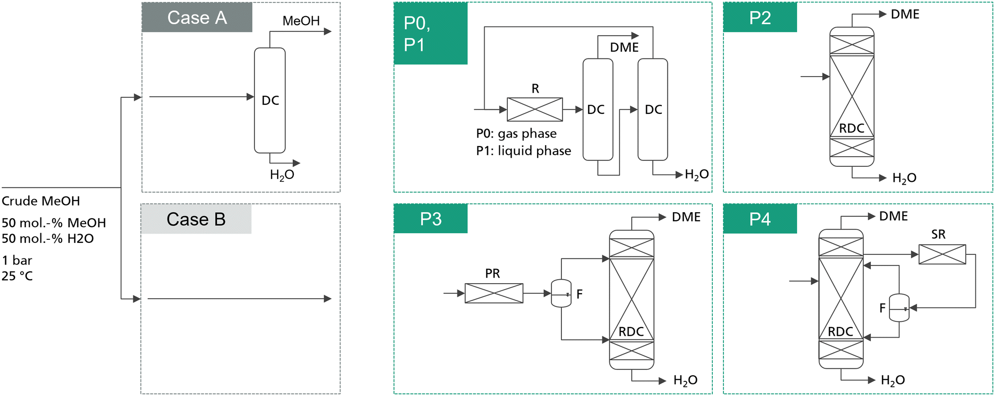 | ||
| Fig. 1 Simplified process flowsheets of the examined process concepts. Detailed flowsheets are presented in the ESI.† P1–P4 are studied for the case of integrating a dedicated crude MeOH distillation column (case A) and for the case of feeding crude MeOH directly into the respective DME process (case B). The conventional process P0 is only analysed including the crude MeOH distillation column. | ||
The reference feedstock for the process is pure methanol. For comparison, crude MeOH feed is considered, consisting of 50 mol% water and 50 mol% MeOH at a temperature of 25 °C. The composition was chosen following Nyári et al.17 and presented a typical composition for a CO2-based MeOH synthesis process. For all the novel process concepts, two cases are distinguished: in the first case, water is removed from the crude MeOH by a dedicated crude MeOH distillation (CMD) step and pure MeOH is fed to the DME process. In the second case, the water containing crude MeOH is fed directly to the respective DME process, thus saving the cost for the dedicated CMD column. For the conventional process, the crude MeOH is always purified. Moreover, all the process concepts are examined for two IER catalysts:
1. The oversulfonated IER A36. Max. operating temperature: 130 °C.
2. The chlorinated IER C400. Max. operating temperature: 160 °C.
The maximum operating temperatures of the catalysts considered in this work are below the manufacturer's specification to avoid catalyst deactivation and increase the lifetime of the catalyst.
In the processes containing a liquid phase fixed bed reactor (P1, P3, P4), the reactor is operated at a reaction pressure of 47 bar (A36) and 76 bar (C400).
Methods
Process design together with energy- and mass balances was performed by process simulation using Aspen Plus V12.1. Using all relevant technical and sizing data from the process simulation, an economic evaluation of the process was conducted using a literature based factorial economic model based on the model by Albrecht et al.,18 which was implemented in Microsoft Excel and is described later. The converged material and energy balances were extracted in the Excel sheet to derive capital expenditures (CAPEX), operational expenditures (OPEX) and total production cost.Process optimization
The reactive distillation process for the DME synthesis exhibits an inherent target conflict between the reboiler duty and column size. Consequently, an economically reasonable process design is only possible by a techno-economic analysis of the process. In this work, each process concept is optimized by minimizing the resulting net conversion cost (NCC). While the process concepts P0 and P2 have been investigated in the literature, P1, P3 and P4 are novel. Consequently, no empirical values regarding the process design variables are available. For this reason, in this work an iterative two-step process design is conducted as shown in Fig. 2.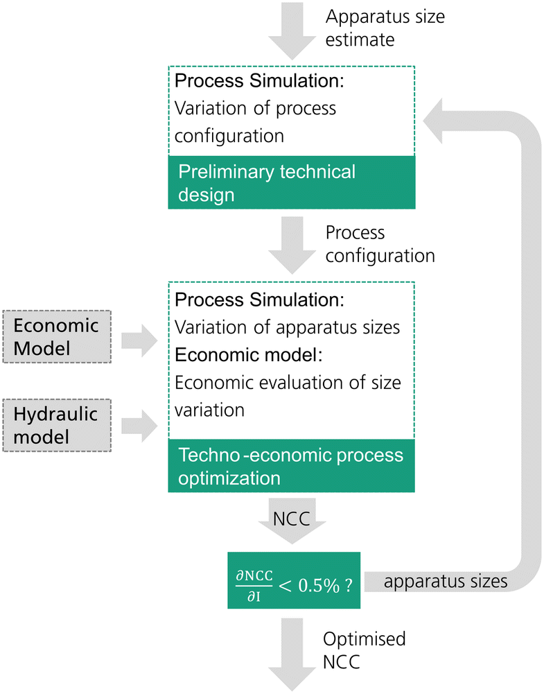 | ||
| Fig. 2 Methodology of the total cost optimized process design of each process. | ||
In a first step, a preliminary technical design study of the process is conducted. Hereby, an initial estimate must be provided for the apparatus sizes (catalyst mass in the RDC and/or reactor size) and the main technical design parameters (e.g. feed stages, withdrawal stage) excluding sizing parameters are then varied by means of a sensitivity study. The varied parameters in each process are shown in Table 1. The case with the minimum energy demand of the process is then selected as the pre-optimized process configuration. For processes P0 and P1, the feed stages to the distillation columns were adopted from Bîldea et al.8 and consequently no preliminary technical design study was required.
| Process | Preliminary technical design | Techno economic optimization |
|---|---|---|
| P0 | — | • mCat,Reactor |
| P1 | — | • mCat,Reactor |
| P2 | • NFeed | • mCat,RDC |
| P3 | • NFeed,DME-rich | • mCat,RDC |
| • NFeed,H2O-rich | • mCat,PR | |
| P4 | • NFeed | • mCat,RDC |
| • NWD | • mCat,SR | |
| • ṄSide | • ṄSide | |
| • NRCY,DME-rich | ||
| • NRCY, H2O-rich |
The second step is the techno-economic process optimization where the optimal apparatus sizes for the current process configuration are identified. A sensitivity study is conducted, varying the size of the RDC and/or reactor. In the case of P4, also the mole flow of the side stream is varied as it has a significant influence on the sizing of the SR. Table 1 summarizes the sizing parameters varied in the techno-economic process optimization. For every simulated case, the NCC are calculated based on the presented economic model. The case resulting in the minimal NCC presents the optimized process sizing for the current process configuration.
Since the sizing of the apparatuses influences the process design, the optimal process configuration obtained in the preliminary technical design may change at different apparatus sizes. Consequently, an iterative methodology was applied and a minimum of two iterations was conducted for each process. When the NCC between the two iterations was reduced by less than 0.5%, the procedure was finished.
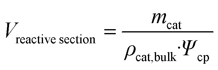
The size variation of the PR/SR was performed by varying only the length of the reactor. The reactor diameter was kept constant to allow an effective heat transfer and maintain isothermal conditions. The size of the RDC was varied in the simulation by modifying the amount of catalyst on each stage. For every case, the column diameter is calculated based on a beforehand derived hydraulic regression function. In practice, a reduced amount of catalyst would also lead to a reduced height of the reactive section and thus a reduced number of theoretical stages. However, as shown in a previous publication,12 this effect can be neglected, since the number of theoretical stages in the reactive section has no significant influence on the reboiler duty of the RDC.
Process flowsheet simulation
Steady-state process simulations were performed using the equation-oriented solution algorithm in Aspen Plus, since the sequential-modular approach was not able to converge the complex flowsheets with numerous design specifications. The thermodynamic data in the simulation platform were implemented using the Peng–Robinson EOS with Wong–Sandler mixing rules and the activity coefficient according to the UNIFAC–PSRK model, using the parameters by Ye et al.19 The pressure drop in all unit operations was neglected.Heat exchangers
All heat exchangers were designed as counterflow shell and tube heat exchangers with a minimum temperature difference of 10 K.20 Cooling water was assumed to be available at 15 °C and a maximum temperature increase of the cooling water by 5 K was considered.18 The heat transition coefficient used in the heat exchangers can be found in the ESI.†Pumps
All pumps are designed as centrifugal pumps with an assumed isentropic efficiency of 80%.21Liquid phase reactor
The liquid phase reactors in processes P1, P2 and P4 are designed as isothermal fixed bed reactors. Consequently, to remove the reaction heat of 23.5 kJ mol−1,9 the reactor is designed as a shell and tube heat exchanger and the catalyst is assumed to be employed inside the tubes with a tube diameter of 0.08 m. While this design is more expensive than an adiabatic design, it allows operation at the highest possible reaction rate while not exceeding the maximum operating temperature of the catalyst. The length and number of tubes were varied according to the identified catalyst mass needed for the desired conversion. For process simulation, the plug flow reactor (PFR) model of Aspen Plus was used. The liquid phase reaction kinetics for the two IER catalysts A36 and C400 proposed by Semmel et al.11 were implemented using a Fortran subroutine. The rate equation and the corresponding parameters used for both catalysts are shown in the ESI.† The bulk density of the MeOH-swollen IER catalyst of 363 kg m−3 was experimentally determined.Gas phase reactor
The gas phase reactor of the conventional process P0 is designed as an adiabatic fixed-bed reactor with an inner diameter of 0.5 m. It is modelled as a PFR using the kinetics by Bercic et al.22 This kinetic expression was fitted for industrial-sized 3 mm particles of γ-Al2O3. The catalyst bulk density is 882 kg m−3.22 It should be noted that there was a correction of the rate equation of the apparent kinetics in the original source very recently.23 The rate equation and the corresponding parameters are shown in the ESI.† Older publications using the uncorrected version of the kinetic model consequently obtained significant deviations in the reaction rate.Reactive distillation column
The RDC is simulated using an equilibrium-based separation approach based on the RADFRAC model, which assumes the liquid and gas phases of each stage to be ideally mixed. On the catalyst containing reactive stages in the middle of the column, the reaction is modelled using the kinetics by Semmel et al.11 implemented with a Fortran subroutine. The top and bottom sections of the column do not contain a catalyst and are modelled as rectifying stages only. The upper rectifying section includes 10 theoretical stages, and the lower rectifying section includes 15 theoretical stages. The reactive section was implemented with 40 theoretical stages.The operating pressure of the RDC is varied by a design specification so that the maximum temperature in the reactive section is equal to the maximum operating temperature of the used catalyst. A second design specification modifies the RR so that the DME purity equals 99.9 mol% under full MeOH conversion. Details regarding the RDC modelling and the thermodynamic property calculation can be found in Semmel et al.12
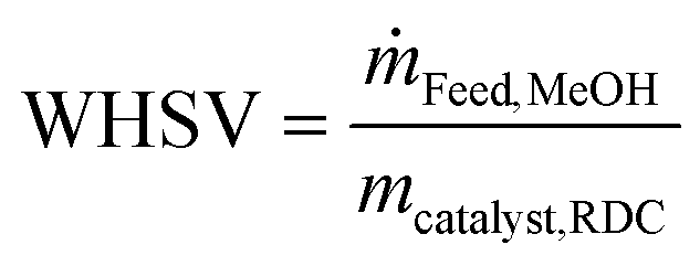
The weight hourly space velocity (WHSV) of the RDC is defined as follows:
 | (1) |
 | (2) |
Distillation columns
The distillation columns in all the processes are modelled using the RADFRAC standard equilibrium-based model in Aspen Plus. Structured packings (Mellapak) with a HETP of 0.5 m (ref. 25) were selected as column internals. The column diameter was calculated with the Aspen internal hydraulics tool.Economic model
Economic evaluation of each process was done based on the factorial method approach. A detailed description of the methodology is described by Albrecht et al.18 According to AACE (Association for the Advancement of Cost Engineering) classes three and four, an accuracy of ±30% can be expected based on this methodology.26 The year 2020 was chosen as the base year. The used economic assumptions are summarized in Table 2.| Parameter | Unit | Value |
|---|---|---|
| Plant capacity | tDME per year | 100![[thin space (1/6-em)]](https://www.rsc.org/images/entities/char_2009.gif) 600 600 |
| Plant availability | h per year | 8000 |
| Location | — | Germany |
| Base year | — | 2020 |
| Project lifetime n | Year | 20 |
| Interest rate i | % | 5 (ref. 20) |
| Working capital share w | — | 0.1 (ref. 18) |
| Exchange rate | €2020 per $2020 | 0.876 (ref. 27) |
| Labor cost | € per h | 41.0 (ref. 28) |
The overall production costs are composed of the CAPEX and OPEX of the plant.
CAPEX
CAPEX is calculated as fixed capital investment (FCI) based on the equipment cost ECi of the main process equipment and Lang factors Fi. Annualized capital cost (ACC) is then derived from FCI using the interest rate i, working capital share w and the plant operation time n according to eqn (3) and (4). The Lang factors are summarized in the ESI.†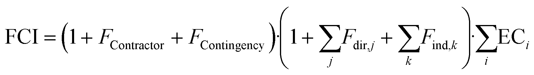 | (3) |
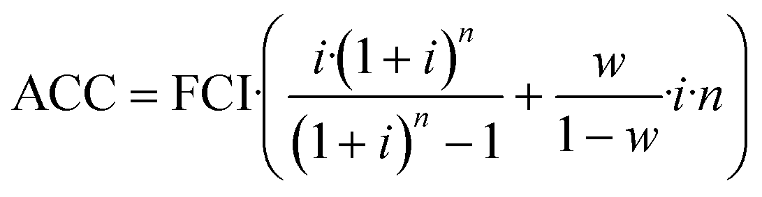 | (4) |
OPEX
OPEX is divided into direct OPEX (OPEXdir) and indirect OPEX (OPEXind). OPEXdir consists of the cost for steam, cooling water and electricity according to eqn (5). Furthermore, the catalyst cost is considered as OPEXdir due to the regular replacement catalysts. In this study, the lifetime of IER was assumed as 1 year and that of γ-Al2O3 as 3 years.30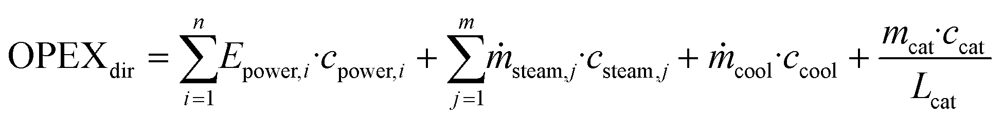 | (5) |
| Operating supplies | Cost |
|---|---|
| a Cost assumed to be identical to comparable oversulfonated IER Amberlyst 35.26 b Cost assumed to be identical to comparable the chlorinated IER Amberlyst 45.26 | |
| LP steam, 4 bar | 22.8 € per t |
| MP steam, 20 bar | 23.1 € per t |
| Cooling water, 15 °C | 0.0035 € per m3 |
| Electricity | 55.72 € per MW h |
| Amberlyst 36 catalysta | 7.5 € per kg |
| C400 catalystb | 18 € per kg |
OPEXind contains all other additional expenses for plant operation excluding operating labour and is calculated using the Lang factors shown in the ESI.† Consequently, OPEXind scales partially with the FCI.
Operating labour
Operating labour was estimated using the correlation for fluid processes by Peters et al.29 shown in the ESI.†Net conversion cost
The net conversion cost (NCC), representing the total cost for producing DME from crude MeOH, is calculated from the ACC, total OPEX and the annual cost for operating labour (OL) according to: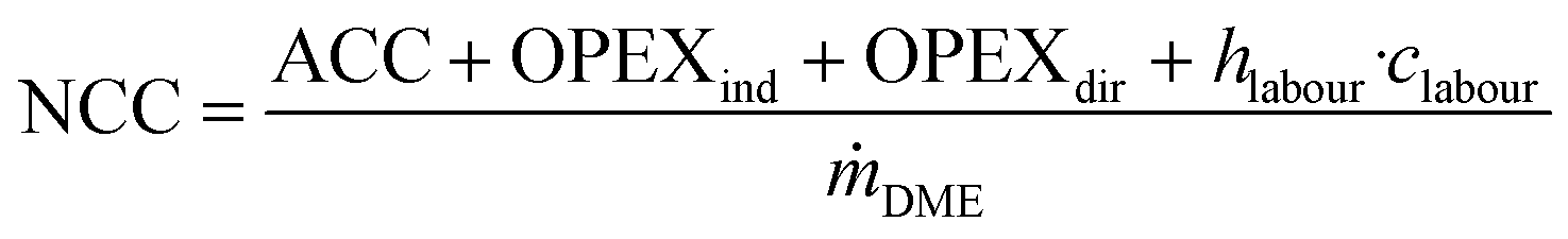 | (6) |
Note that this is the same equation as that typically used for the calculation of the NPC. However, since the crude MeOH feedstock cost is not accounted for in the OPEXdir, the resulting cost is the conversion cost, comprising the cost for upgrading crude MeOH to DME, rather than the NPC including the feedstock cost. However, the NCC can be directly correlated to give the total NPC based on the specific crude MeOH feedstock cost cCrude MeOH and the mass ratio between the feedstock and product according to the stoichiometry:
 | (7) |
 | (8) |
Results and discussion
In the following section, first, the final configuration and KPIs of the optimized processes P0–P4 are presented and discussed. Then, the processes are compared at their respective optimal configuration and a systematic comparison between the two feed cases is done for every concept, meaning that the cost for the CMD is added to the DME processes if operated with pure MeOH feed. After the DME process with the lowest NCC is determined, a sensitivity study for this process is shown and the process is heat-integrated with a CO2-based MeOH plant. Furthermore, the NPC is given in dependence of the crude MeOH feedstock price.Optimization of each process
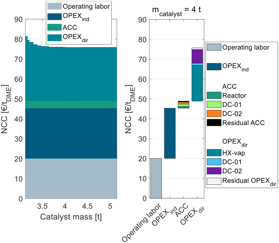 | ||
| Fig. 3 Process cost of the conventional process P0 in dependence of the catalyst mass in the conventional gas-phase reactor broken down into ACC, OPEXind, and OPEXdir. | ||
The process P0 is dominated by indirect and direct OPEX, the ACC only contributes a minor share to the NCC. For a small catalyst mass <4 t, the OPEXdir decreases with increasing catalyst mass. This can be explained by the increasing MeOH conversion in the reactor and a smaller amount of unreacted MeOH that needs to be recycled and purified in DC-02. At a catalyst mass of 4 t, the reactor approaches equilibrium and consequently the additional increase in catalyst mass has no beneficial influence on the OPEXdir but only leads to increased ACC. Correspondingly, the NCC reaches a minimum at 4 t. This value is significantly smaller than the catalyst mass reported by Bîldea et al.8 or Michailos et al.30 since these publications are still based on the erroneous kinetic data from the original publication. The authors of the original publication recently published a correction23 of the kinetic model, which was adopted in this work leading to significantly smaller reactor sizes than reported so far. Regarding the feed MeOH mass flow of 17.5 t h−1 for the DME production capacity of 100 ktpa, this corresponds to WHSV = 4.4 h−1. A detailed cost breakdown at the optimal catalyst mass is given on the right side of Fig. 3. The ACC consists almost equally of the reactor, the two distillation columns and the residual apparatuses (pump and heat exchangers). The OPEXdir is dominated by the steam demand for the evaporator HX-vap and the reboiler of DC-02. The catalyst cost is included in the residual OPEXdir and is negligible.
The overall heat demand of the process is 762 kW h tDME−1, which is in accordance with the results of Michailos et al.30 (904 kW h tDME−1) and Bîldea et al.8 (714 kW h tDME−1). The resulting NCC is 75.7 € per tDME. Table 4 sums up the key performance indicators (KPIs) of the process P0 with the optimized reactor size.
| Parameter | Unit | Pure MeOH |
|---|---|---|
| γ-Al2O3 | ||
| m Cat,Reactor | t | 4.0 |
| X MeOH,Reactor | — | 0.8 |
| RRDC-01 | — | 3.8 |
| RRDC-02 | — | 1.5 |
| Q Heat | kW h tDME−1 | 762 |
| NCC | € per tDME | 75.7 |
| Parameter | Unit | Pure MeOH | Crude MeOH | ||
|---|---|---|---|---|---|
| A36 | C400 | A36 | C400 | ||
| m Cat,Reactor | t | 18.0 | 8.8 | 24.1 | 16.2 |
| X MeOH,Reactor | — | 0.45 | 0.88 | 0.16 | 0.56 |
| RRDC-01 | — | 2.0 | 0.5 | 10.1 | 1.7 |
| RRDC-02 | — | 1.1 | 1.7 | 1.1 | 1.3 |
| Q Heat | kW h tDME−1 | 1393 | 258 | 5914 | 1005 |
| NCC | € per tDME | 135.0 | 66.9 | 346.9 | 116.7 |
For pure MeOH feed and A36, the cost-optimal configuration is a reactor with 18 t of catalyst, corresponding to a single-pass MeOH conversion of 45%. Using C400 instead, a smaller reactor with 8.8 t allows a conversion of 88% due to the significantly higher reaction rate enabled by the higher temperature stability of C400. Compared to the conventional gas-phase reaction, the liquid phase dehydration entails the advantage of a higher equilibrium conversion due to the lower temperatures (XMeOH,Equil. = 93%@160 °C (ref. 11)). However, the slower reaction kinetics demands a higher catalyst mass (8.8 t C400 vs. 4 t γ-Al2O3).
The RR of DC-01 is significantly lower, as the higher conversion leads to a lower MeOH fraction and higher DME fraction, simplifying the separation. Due to the higher conversion with C400, less MeOH needs to be recycled, which reduces the mass flow in both columns. For this reason, the overall heat demand of the process QHeat with C400 is 81% lower than with A36. The NCC is 50% lower.
For the crude MeOH feed, the same trend can be observed with C400 leading to less catalyst mass, yet a higher MeOH conversion and consequently a lower heat demand and NCC. Compared to using pure MeOH however, the cost-optimal reactor size is bigger and exhibits a smaller MeOH conversion since the reaction is inhibited by the high water concentration.
| Parameter | Unit | Pure MeOH | Crude MeOH | ||
|---|---|---|---|---|---|
| A36 | C400 | A36 | C400 | ||
| N Feed | — | 9 | 9 | 50 | 30 |
| m Cat,RDC | t | 40.4 | 17.2 | 56.8 | 26.4 |
| RR | — | 7.6 | 5.2 | 12.8 | 8.3 |
| Q Heat | kW h tDME−1 | 897 | 569 | 1515 | 914 |
| NCC | € per tDME | 95.2 | 69.8 | 134.3 | 91.0 |
To analyze this process in more detail, Fig. 4 shows exemplarily for C400 and pure MeOH feed the NCC of process P2 broken down into ACC, OPEXind and OPEXdir and operating labor on the left side.
 | ||
| Fig. 4 Heat demand and NCC of the RD process P2 with C400 and pure MeOH feed in dependence of the catalyst mass in the RDC broken down into ACC, OPEXind, and OPEXdir (left) as well as detailed cost breakdown at the cost optimum (right). | ||
The figure shows the RDC-inherent target conflict between capital expenses and operating expenses: while a small RDC with little catalyst mass leads to a low ACC, a high RR and consequently a high energy demand are required to achieve the desired full MeOH conversion in the RDC. Increasing the catalyst mass of the RDC increases the ACC, since the column size and the amount of catalytic packing increase but reduce the RR and OPEXdir so that an optimum catalyst mass of 17.2 t can be identified. The corresponding WHSV is 1.02 h−1. The exact position of the minimum depends on all assumptions influencing the ACC or OPEX. While only one cost optimal RDC size exists, this optimum is rather “flat”. Consequently, the RDC size and the resulting energy demand of the process can be designed in a wide range without the NCC deviating significantly from the optimal configuration. Also, in the case of temporally reduced feed availability, the plant can be operated at lower WHSV which will reduce the specific energy demand of the plant.
Compared to the conventional process P0, the RD process is characterized by a higher ACC which can majorly be attributed to the higher required catalyst mass due to the significantly lower reaction temperature. The OPEXdir is comparable for both processes: while the RD process P2 has a lower steam cost due to a lower energy demand (569 kW h tDME−1vs. 762 kW h tDME−1), this benefit is compensated by the significantly higher catalyst cost to the higher catalyst mass and the lower assumed catalyst lifetime of IER compared to γ-Al2O3. The right side of Fig. 4 shows the detailed cost breakdown at the optimum catalyst mass. The ACC is dominated by the RDC, particularly the cost of the catalytic packing internals and the cost for the RDC shell, reboiler and condenser. In contrast, the cost for the other process components (pump, heat exchangers) and the structured packing in the RDC is almost negligible. The OPEXdir is dominated by the heat demand of the RDC reboiler, but the influence of the catalyst cost is also significant.
In comparison with C400, process P2 with A36 shows its optimum at a significantly higher catalyst mass of 40.8 t. Nevertheless, the required RR is higher than that for C400, again underlying the great benefit of the higher reaction rate through higher temperature stability. As a consequence, C400 is able to reduce both the RDC size and the energy demand compared to A36.
For crude MeOH, the optimal feed stage moves down to the bottom of the reactive section, where the water-containing crude MeOH better fits the column profile. As another consequence of the crude MeOH feed, the energy demand and the required catalyst mass are higher as the reaction kinetics is hampered by the higher water content of the feed and more water needs to be evaporated in the reboiler in total. Also, for crude MeOH C400 shows significant improvements compared to A36 regarding the energy demand and NCC. Interestingly, even C400 with crude MeOH feed leads to a lower NCC than A36 with pure MeOH feed.
| Parameter | Unit | Pure MeOH | Crude MeOH | ||
|---|---|---|---|---|---|
| A36 | C400 | A36 | C400 | ||
| N Feed,DME-rich | — | 7 | 9 | 9 | 7 |
| N Feed,H2O-rich | — | 50 | 56 | 56 | 54 |
| m Cat,PR | t | 10.8 | 8.4 | 8.2 | 11.1 |
| X MeOH,PR | — | 0.52 | 0.91 | 0.09 | 0.52 |
| m Cat,RDC | t | 23.0 | 1.6 | 40.0 | 9.2 |
| RR | — | 5.7 | 0.8 | 13.1 | 6.2 |
| Q Heat | kW h tDME−1 | 756 | 238 | 1530 | 783 |
| NCC | € per tDME | 88.9 | 52.4 | 129.5 | 85.5 |
Besides the two feed stages, the optimal size needs to be determined for the PR and RDC. While a larger PR leads to increased cost for the reactor, the increased MeOH conversion allows the RDC to be smaller or operate at a lower RR. Consequently, a target conflict between the PR size and RDC size is present in the system.
Fig. 5 shows this interplay between the PR and RDC sizes. For each RDC size an optimal PR size can be identified. With increasing RDC size, the optimal PR size decreases, the best configuration globally is a PR with 10.8 t and an RDC with 23 t of catalyst.
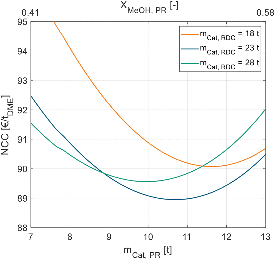 | ||
| Fig. 5 NCC of process P3 in dependence of the catalyst mass in the liquid-phase PR for different RDC sizes. Exemplary for pure MeOH feed and A36. | ||
Comparing the influence of the catalyst and feed, similar trends to those in the previous processes can be observed: the use of C400 leads to a lower required catalyst mass in the RDC and PR, a lower RR in the RDC and a lower NCC of the process. Also, the crude MeOH feed results in a higher catalyst mas, higher RR and higher NCC.
Comparing process P3 to P2 based on the KPIs presented in Tables 6 and 7, the benefit of the PR can be quantified: for the pure MeOH feed, the NCC is reduced by 7% (A36) and 25% (C400), respectively. The heat demand is reduced even further by 16% (A36) or 58% (C400). Interestingly, despite adding a unit operation compared to the stand-alone RDC, the total catalyst mass in the optimal configuration is reduced, in the case of C400 with pure MeOH feed even by 52%. This can be explained by a more effective utilisation of the catalyst in the PR, since an isothermal operation is possible as opposed to the immanent RDC temperature profile. The PR and RDC complement each other: at conversion significantly below the chemical equilibrium, the PR is beneficial as it delivers the ideal reaction temperature and is not significantly equilibrium inhibited. The cumbersome conversion of the residual MeOH in contrast is more effectively performed in the RDC, where the in situ product removal from the chemical equilibrium allows a full conversion.
For the crude MeOH feed, the benefit of the PR is significantly less pronounced with the NCC only decreasing by 4% (A36) and 6% (C400). This shows a clear disadvantage of the PR concept with crude MeOH: the crude MeOH feed directly enters the PR, where the reaction is heavily inhibited by water and consequently the MeOH conversion is significantly lower compared to the pure MeOH feed.
| Parameter | Unit | Pure MeOH | Crude MeOH | ||
|---|---|---|---|---|---|
| A36 | C400 | A36 | C400 | ||
| N Feed | — | 7 | 11 | 56 | 15 |
| N WD | — | 7 | 13 | 7 | 9 |
| N RCY,DME-rich | 9 | 11 | 7 | 7 | |
| N RCY,H2O-rich | 58 | 56 | 56 | 56 | |
| Sidestream | kmol h−1 | 375 | 675 | 250 | 525 |
| m Cat,SR | t | 10.5 | 7.3 | 10.0 | 8.7 |
| X MeOH,SR | — | 0.66 | 0.86 | 0.76 | 0.85 |
| m Cat,RDC | t | 23.2 | 1.0 | 28.4 | 10.4 |
| RR | — | 5.5 | 1.5 | 12.9 | 5.5 |
| Q Heat | kW h tDME−1 | 727 | 317 | 1555 | 716 |
| NCC | € per tDME | 87.7 | 54.2 | 123.5 | 79.8 |
For pure MeOH and both catalysts and crude MeOH with A36, the feed stage NFeed is similar to the stand-alone RD process P2. For crude MeOH and C400 however, a feed stage at the top of the reactive section proved to be more efficient than in the lower rectifying section. For both catalysts and feeds, the configurations of the withdrawal and recycling stages are almost identical. The withdrawal stage NWD is located at the top or right above the reactive section where the MeOH concentration in the column is the highest. An exemplary column profile is given in the ESI.† The position of the recycling stages NRCY,DME-rich and NRCY,H2O-rich is almost identical to the feed stages NFeed,DME-rich and NFeed,H2O-rich in P3. For the pure MeOH feed and both catalysts, also the sizes of the SR and RDC are very similar to the sizes of the RDC and PR obtained in P3. Consequently, also the RR, heat demand and the resulting NCC are comparable. The similarity between both processes can be explained, since in both processes (nearly) pure MeOH is fed to the reactor. While in P3, pure MeOH is fed directly to the reactor, in P4 it enters the RDC first, and a MeOH-rich stream is withdrawn from the top of the reactive section. Thus, the PR in P3 and the SR in P4 operate under nearly identical conditions and therefore, the similar process configuration and performance of P3 and P4 can be explained.
For the crude MeOH feed in contrast, the process configuration and performance of P3 and P4 differ from each other: for A36 a MeOH conversion of 76% is achieved in the SR, while in the PR only 9% conversion is reached in the optimal configuration. For C400, 85% of the fed MeOH is converted in the SR and only 52% in the PR. As mentioned before, the process performance of P3 suffers significantly from the crude MeOH feed, since the reaction in the PR is strongly inhibited by the water content of the feed. Contrarily, in process P4, the crude MeOH is first fed to the RDC, and a MeOH-enriched side stream is fed to the SR. This way, the water inhibition in the SR is significantly reduced compared to that in the PR and consequently process P4 performs better with the crude MeOH feed than P3. Precisely, in the case of C400, P4 leads to 3% higher NCC than P3 for the pure MeOH feed, but to 7% lower NCC than P3 for the crude MeOH feed.
Process comparison
In all process concepts P1–P4, the NCC is significantly higher when using the crude MeOH (case B) instead of the pure MeOH (case A) feedstock. However, to allow a fair comparison, the cost for the dedicated CMD must be accounted for in the case when pure MeOH is fed to the DME process. For this reason, the NCCCMD of converting crude MeOH to pure MeOH with the CMD column was calculated using the same economic model as for the DME processes. The resulting NCCCMD of 55.8 € per tDME was added to all processes P1–P4 fed with pure MeOH. A detailed table with the KPIs of the CMD is given in the ESI.†Fig. 6 shows the results of all the processes for both catalysts and both feed cases. The cost for the CMD is illustrated as a grey bar. The DME processes operated with A36 are illustrated as a light green (pure MeOH feed, case A) or dark green (crude MeOH feed, case B) bar and the processes operated with C400 are illustrated as a light blue (pure MeOH feed, case A) or dark blue (crude MeOH feed, case B) bar.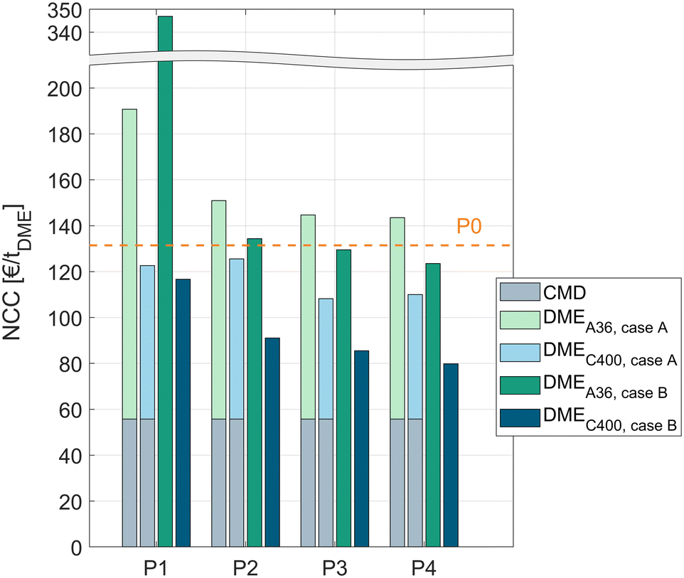 | ||
| Fig. 6 Overview of total NCC for all 4 DME processes with both catalysts for pure MeOH feed (case A) and crude MeOH feed (case B) including the cost for the CMD in case A. Comparison with the conventional process P0. | ||
The cost of the conventional process P0 including the cost for the CMD is shown as a dashed line.
For all the process concepts, the use of C400 leads to significant cost reduction compared to A36. Consequently, the higher catalyst cost of C400 and the higher pressure demand of the process due to the higher operating temperature of C400 are clearly overcompensated by the increased reaction rate, resulting in lower apparatus sizes and – indirectly – a lower energy demand.
The liquid phase reaction process P1 exhibits a very high NCC when using A36; especially in case B, the NCC is nearly 3 times higher than for the conventional process P0. Using the more active C400 instead, the process performs significantly better, outperforming the conventional process slightly. Remarkably, with C400 the process concept P1 performs also well with the crude MeOH feed (case B) yielding a slightly lower cost than in case A although the water containing crude MeOH is directly fed to the reactor without prior water removal.
The RD process P2 generally shows a lower NCC than P1. For both catalysts, directly feeding crude MeOH is preferable to using a dedicated CMD column. For C400, this leads to a NCC reduction of 27%. Compared to the conventional process, P2 with C400 and crude MeOH feed exhibits 31% lower conversion costs.
Complementing the RDC with a PR or SR allows even lower conversion costs. The best process overall is the RDC with a SR and direct crude MeOH feed to the RDC. In this case, the NCC can be reduced by 39% compared to the conventional process. When pure MeOH feed is already available, process P3 with C400 presents the best process with a 31% NCC reduction compared to the conventional process.
Sensitivity study
A techno-economic analysis is always based on a manifold of economic parameters and assumptions. To estimate the influence of some economic parameters on the overall NCC, a sensitivity study was conducted. This was done exemplarily for the best process P4 with C400 and crude MeOH feed. Hereby the optimal SR and RDC sizes were re-evaluated for every parameter variation instead of maintaining the original configuration that might be non-optimal for the varied parameters. For example, in the case of increased steam cost, the configuration would shift towards a bigger SR and RDC to reduce the energy demand at the expense of higher CAPEX. The results of the sensitivity study are shown in Fig. 7.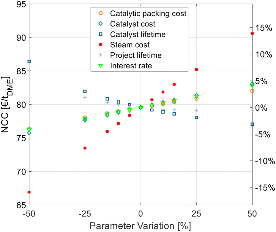 | ||
| Fig. 7 Sensitivity analysis of economic parameters on the NCC of process P4 with C400 and crude MeOH feed (case B). | ||
The cost of the catalytic packing, catalyst cost and catalyst lifetime have a significant, but comparatively small influence on the NCC. The same applies to the economic parameters, namely the interest rate and project lifetime. The steam cost presents the most sensitive parameter, since it dominates the OPEX of the process, which presents a high share of the NCC. Yet, a 50% increase of steam cost increases the NCC by less than 15%, thus underlying the significance of the values obtained in this work.
Process integration
The comparison and optimization of the processes were conducted with crude MeOH at 25 °C as the system input. No heat integration was performed to allow a systematic comparison independent of system specific boundary conditions. In practice however, a heat integration of the DME synthesis with the MeOH synthesis is a logical step since the exothermic heat of the MeOH reactor can be integrated into the DME process. Especially when crude MeOH is used as the feedstock for DME synthesis and the dedicated CMD column is omitted, significant amounts of heat are available from the MeOH synthesis. To examine the influence of heat integration, the best DME process presented in the previous chapter (P4, C400, case B) was heat integrated with MeOH synthesis. The process configuration and apparatus sizes of the DME process are the same as presented in Table 8. The MeOH plant was simulated in Aspen Plus according to Mantei et al.20 Key technical parameters of the MeOH process are shown in the ESI.† The flowsheet of the integrated process is shown in Fig. 8. All heat exchangers for cooling are operated with cooling water.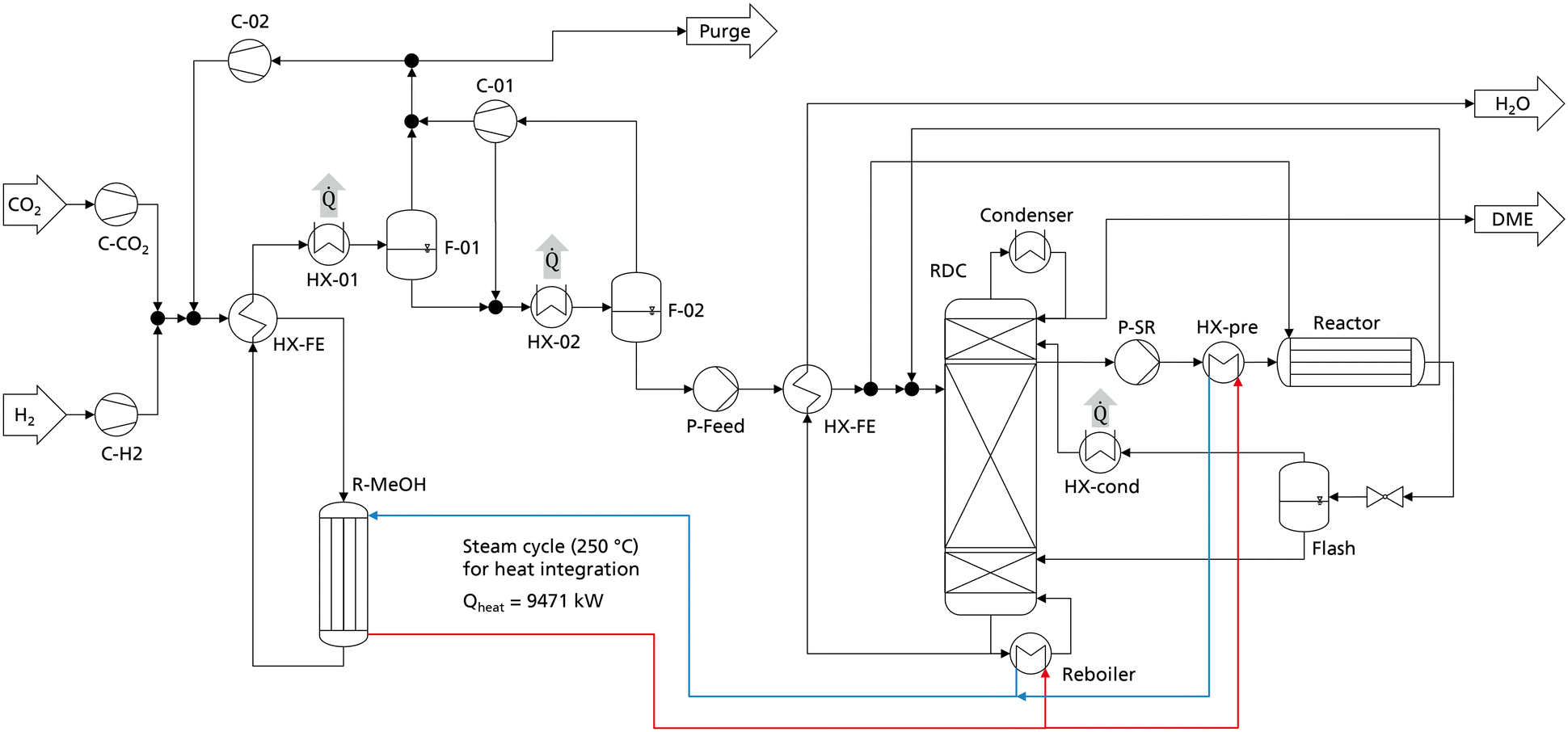 | ||
| Fig. 8 Flowsheet of the heat integrated MeOH and DME synthesis plant producing DME from CO2 and H2. | ||
The simulated MeOH synthesis plant has an annual production capacity of 218640 t crude MeOH, corresponding to 140000 t of pure MeOH. The isotherm MeOH reactor operates at 250 °C and releases an exothermic heat of 9.47 MW, corresponding to 754 kW h tDME−1. The RDC reboiler operates at 190 °C and the side reactor feed heat exchanger HX-pre operates at 160 °C, allowing the full integration of the MeOH exothermic heat into the DME process. As the MeOH reactor is a steam cooled tube and shell type reactor, the generated steam can directly be heat integrated with the reboiler of the RDC and the heat exchanger HX-pre without the necessity of additional process equipment. The heat released at the medium temperature level in the condensation of the MeOH synthesis reactor product (HX-01) does not need to be heat integrated and is consequently still available e.g., for a direct air capture process.
Fig. 9 breaks down the heat demand of the DME process P4 considering this heat integration.
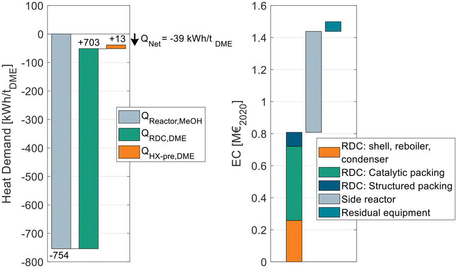 | ||
| Fig. 9 Energy demand of process P4 when heat integrated with the reactor of a MeOH synthesis plant (left) and equipment cost breakdown of the DME process (right). | ||
The EC breakdown on the right part of Fig. 9 shows that the RDC and SR contribute almost equally to the overall EC. The residual components – namely heat-exchangers, pumps and the flash separator – are almost negligible. The cost of the RDC is dominated by the catalytic packing rather than the cost for the column shell itself. This detail shows again the benefit of using high-temperature stable IER since the higher activity allows a smaller reactive section, which leads to proportionally decreasing cost for the catalytic packing. In contrast, the additional cost for the pressure stability of the column plays a less important role. Moreover, the large cost share of the catalytic packing shifts the focus to potential alternative methods of employing the catalyst in the RDC, such as catalyst bales or the placement on trays.31,32
On the left side of the diagram, the exothermic heat of the MeOH reactor is displayed as a negative energy demand. Consequently, it is offset against the two energy demanding apparatuses of the DME process, namely the RDC and the SR feed heat exchanger HX-pre. From the illustration, a net heat demand of QNet = −39 kW h tDME−1 at the MeOH reaction temperature can be identified, implying that the integrated process releases more heat than it consumes. The only energy demand of the DME process is the electric energy required for the pumps P-Feed and P-SR which is 11.4 kW hel tDME−1. The MeOH synthesis plant has no external heat demand either, as a feed to product heat exchanger is sufficient to heat up the feed gas. Overall, process P4 allows a DME production process from CO2 and H2 feedstocks with no external heat demand. Instead, the process entails the possibility of exporting 39 kW h of MP steam per ton of DME produced. This is a decisive advantage in the PtX context, where plants are more likely to be constructed in remote areas without the infrastructure commonly found in chemistry parks. Integrating the “free” heat from the MeOH synthesis reduces the NCC of the process from 79.6 € per tDME (no heat integration, Table 8) to 55.6 € per tDME as the steam costs can be omitted. As the amount of exothermic heat is even higher than the heat demand, in this process configuration, the residual excess heat of 39 kW h tDME−1 would be dissipated. Consequently, by reoptimizing the process under the boundary conditions of using the entire available exothermic heat, a new optimal configuration can be found that is characterized by a higher reboiler duty of the RDC but lower CAPEX. Table 9 sums up the KPIs at this process design configuration.
| Parameter | Unit | Crude MeOH |
|---|---|---|
| C400 | ||
| N Feed | — | 15 |
| N WD | — | 9 |
| N RCY,DME-rich | 7 | |
| N RCY,H2O-rich | 56 | |
| Sidestream | kmol h−1 | 525 |
| m Cat,SR | t | 8.9 |
| X MeOH,SR | — | 0.87 |
| m Cat,RDC | t | 8.8 |
| RR | — | 5.9 |
| Q Heat | kW h tDME−1 | 0 |
| NCC | € per tDME | 54.4 |
Calculation of the NPC
All results presented to this point reflect the NCC, considering all cost related to the DME synthesis itself, but disregarding the cost for the MeOH feedstock. Since the crude MeOH cost is dependent on many factors, Fig. 10 shows the NPC of DME produced via P4 with C400 and crude MeOH feed as a function of the crude MeOH cost. The process design configuration of P4 was chosen as shown in Table 9. For comparison, the theoretical minimum NPC is shown. In this case, the OPEX and CAPEX for the DME process are neglected and only the feedstock cost is considered.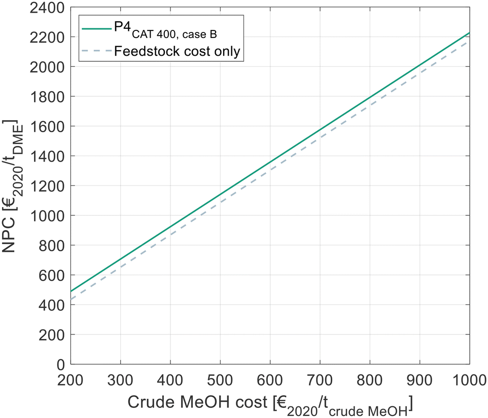 | ||
| Fig. 10 NPC of DME in dependence of the crude MeOH feedstock cost, as calculated by eqn (7). Cost for the optimal process presented in this work and comparison with the theoretical minimal cost, when neglecting all cost for the DME process. | ||
The NPC increases linearly with the crude MeOH cost, thereby reflecting the linear character of eqn (7). The NCC of the DME process is visible as the vertical distance between the two lines in the diagram.
Conclusions and outlook
DME shows very promising properties for global transport of green hydrogen. Shifting the reaction phase of DME synthesis from gas to liquid opens up new possibilities towards the design of novel efficient process concepts. In the scope of this work, four process concepts were proposed and rigorously optimized with respect to the ideal process configuration and the ideal size of the RDC and/or reactor. The used process simulation platform was validated in previous studies based on kinetic measurements and under industrially relevant conditions in a pressure reactive distillation column. Based on the respective optimal design, all processes were systematically compared regarding technical and economic parameters. Hereby, every process concept was evaluated by comparing two employed IER catalysts and comparing pure and crude MeOH feed, respectively. Furthermore, the conventional gas-phase process was simulated and evaluated as a reference case.Throughout all proposed processes, the use of high-temperature stable IER C400 proved to be significantly beneficial in terms of the energy demand and production cost. Consequently, the higher operating pressure with this catalyst can be overcompensated by the higher activity. Employing C400, all proposed processes show lower production cost than the conventional process. This can be attributed to the lower energy demand of the liquid phase processes. Interestingly, the reduced energy demand overcompensates the higher CAPEX, which can be traced back to the more expensive isothermal reactor required in liquid phase DME synthesis and/or the high cost for the catalytic packings in the RDC.
All processes with the RDC (P2–P4) benefit from directly feeding crude MeOH to the DME process as opposed to prior purification in a CMD column. While the stand-alone RD process P2 enables a 31% lower production cost than the conventional gas phase process, the RD process can be optimized even further, when complementing the RDC with a pre-reactor (P3) or side-reactor (P4). Despite the additional unit operation, these two process concepts allow a more efficient process and a reduced catalyst mass. Process P3 presents the lowest production cost for the pure MeOH feed, allowing a 31% reduction of NCC compared to the conventional process. When feeding crude MeOH however, process P4 is superior, as the crude MeOH is purified in the RDC prior to entering the reactor. Overall, process P4 with crude MeOH feed and employing C400 presents the best process, leading to a 39% NCC reduction compared to the conventional gas-phase process. By heat integration of this process with a CO2-based MeOH synthesis, a NCC of 54.4 € per tDME was achieved and it was demonstrated that a plant without an external heat demand can be realized, presenting a particularly beneficial process concept in the PtX context. This novel process configuration allows economically competitive DME production at a large scale relying on state-of-the-art process components.
Abbreviations
| A36 | Amberlyst 36 |
| AACE | Association for the Advancement of Cost Engineering |
| ACC | Annual capital cost |
| C400 | Treverlyst CAT 400 |
| CAPEX | Capital expenditure |
| CEPCI | Chemical engineering plant cost index |
| CMD | Crude methanol distillation |
| CO | Carbon monoxide |
| CO2 | Carbon dioxide |
| DME | Dimethyl ether |
| EC | Equipment cost |
| FCI | Fixed capital investment |
| H2 | Hydrogen |
| H2O | Water |
| HETP | Height equivalent to a theoretical plate |
| IER | Ion exchange resin |
| KPI | Key performance indicator |
| LP | Low pressure |
| MeOH | Methanol |
| MP | Medium pressure |
| Mtpa | Million tonnes per annum |
| NCC | Net conversion cost |
| NPC | Net production cost |
| OL | Operating labour |
| OPEX | Operational expenditure |
| PFR | Plug flow reactor |
| PR | Pre-reactor |
| RD | Reactive distillation |
| RDC | Reactive distillation column |
| RR | Reflux ratio |
| SR | Side-reactor |
| WHSV | Weight hourly space velocity |
Latin symbols
| c | Specific cost |
| E power | Electrical energy |
| F i | Lang factor |
| h | Working hours |
| i | Interest rate |
| L | Lifetime |
| m | Mass |
| n | Project lifetime |
| N | Stage number of the distillation column |
| Q | Heat demand |
| V | Volume |
| w | Working capital share |
| X | Conversion |
Greek symbols
| ρ cat,bulk | Bulk density of the catalyst |
| Ψ cp | Volume fraction of the catalyst bulk in catalytic packing |
Indices
| Cat | Catalyst |
| Cool | Cooling medium |
| Dir | Direct |
| i | Index |
| Ind | Indirect |
| k | Index |
| Power | Electric power |
| RCY | Recycle |
| WD | Withdrawal |
Conflicts of interest
The authors declare that they have no known competing financial interests or personal relationships that could have appeared to influence the work reported in this paper.Acknowledgements
Deutsche Bundesstiftung Umwelt (DBU) is gratefully acknowledged for funding the work of Malte Semmel (20020/662). Special thanks are dedicated to the group Power to Liquids at the Fraunhofer Institute for Solar Energy Systems.References
- M. van der Spek, C. Banet, C. Bauer, P. Gabrielli, W. Goldthorpe, M. Mazzotti, S. T. Munkejord, N. A. Røkke, N. Shah, N. Sunny, D. Sutter, J. M. Trusler and M. Gazzani, Perspective on the hydrogen economy as a pathway to reach net-zero CO 2 emissions in Europe, Energy Environ. Sci., 2022, 15, 1034–1077 RSC.
- M. Wietschel, L. Zheng, M. Arens, C. Hebling, O. Ranzmeyer, A. Schaadt, C. Hank, A. Sternberg, S. Herkel, C. Kost, M. Ragwitz, U. Herrmann and B. Pfluger, Metastudie Wasserstoff – Auswertung von Energiesystemstudien, Studie im Auftrag des Nationalen Wasserstoffrats, Fraunhofer ISI, Fraunhofer ISE, Fraunhofer IEG (Hrsg.), Karlsruhe, Freiburg, Cottbus, 2021.
- IEA, International Energy Agency, Global Hydrogen Review 2022, Paris, 2022, https://www.iea.org/reports/global-hydrogen-review-2022 Search PubMed.
- Hydrogen Council, Hydrogen Insights 2023. An update on the state of the global hydrogen economy, with a deep dive into North America, 2023, https://hydrogencouncil.com/wp-content/uploads/2023/05/Hydrogen-Insights-2023.pdf, (accessed 17 July 2023) Search PubMed.
- P. Schühle, R. Stöber, M. Semmel, A. Schaadt, R. Szolak, S. Thill, M. Alders, C. Hebling, P. Wasserscheid and O. Salem, Dimethyl ether/CO2 – a hitherto underestimated H2 storage cycle, Energy Environ. Sci., 2023, 16, 3002–3013 RSC.
- S. H. N. Xydas, LPG-DME Blends Workshop. WLPGA rLPG/rDME Activities, Zurich, 2022 Search PubMed.
- Fact Sheet. rDME Overview, 2022, https://www.aboutdme.org/aboutdme/files/cclibraryfiles/filename/000000004180/rDME_Fact_Sheet_General.pdf, (accessed 13 February 2023) Search PubMed.
- C. S. Bîldea, R. Győrgy, C. C. Brunchi and A. A. Kiss, Optimal design of intensified processes for DME synthesis, Comput. Chem. Eng., 2017, 105, 142–151 CrossRef.
- M. Semmel, R. E. Ali, M. Ouda, A. Schaadt, J. Sauer and C. Hebling, in Power to Fuel, ed. G. Spazzafumo, Elsevier, 2021, pp. 123–151 Search PubMed.
- M. de Falco, M. Capocelli and G. Centi, Dimethyl ether production from CO2 rich feedstocks in a one-step process: Thermodynamic evaluation and reactor simulation, Chem. Eng. J., 2016, 294, 400–409 CrossRef CAS.
- M. Semmel, L. Steiner, M. Bontrup, J. Sauer and O. Salem, Catalyst screening and reaction kinetics of liquid phase DME synthesis under reactive distillation conditions, Chem. Eng. J., 2022, 140525 Search PubMed.
- M. Semmel, I. Bogatykh, B. Steinbach, J. Sauer, J.-U. Repke and O. Salem, Demonstration and experimental model validation of the DME synthesis by reactive distillation in a pilot-scale pressure column, React. Chem. Eng., 2023 10.1039/D3RE00200D.
- S. Hosseininejad, A. Afacan and R. E. Hayes, Catalytic and kinetic study of methanol dehydration to dimethyl ether, Chem. Eng. Res. Des., 2012, 90, 825–833 CrossRef CAS.
- N. K. Gor, N. A. Mali and S. S. Joshi, Intensified reactive distillation configurations for production of dimethyl ether, Chem. Eng. Process., 2020, 149, 107824 CrossRef CAS.
- Z. Lei, Z. Zou, C. Dai, Q. Li and B. Chen, Synthesis of dimethyl ether (DME) by catalytic distillation, Chem. Eng. Sci., 2011, 66, 3195–3203 CrossRef CAS.
- T.-W. Wu and I.-L. Chien, A Novel Energy-efficient Process of Converting CO2 to Dimethyl Ether with Techno-economic and Environmental Evaluation, Chem. Eng. Res. Des., 2021, 177, 1–12 CrossRef.
- J. Nyári, M. Magdeldin, M. Larmi, M. Järvinen and A. Santasalo-Aarnio, Techno-economic barriers of an industrial-scale methanol CCU-plant, J. CO2 Util., 2020, 39, 101166 CrossRef.
- F. G. Albrecht, D. H. König, N. Baucks and R.-U. Dietrich, A standardized methodology for the techno-economic evaluation of alternative fuels – A case study, Fuel, 2017, 194, 511–526 CrossRef CAS.
- K. Ye, H. Freund and K. Sundmacher, Modelling (vapour+liquid) and (vapour+liquid+liquid) equilibria of {water (H2O)+methanol (MeOH)+dimethyl ether (DME)+carbon dioxide (CO2)} quaternary system using the Peng–Robinson EoS with Wong–Sandler mixing rule, J. Chem. Thermodyn., 2011, 43, 2002–2014 CrossRef CAS.
- F. Mantei, R. E. Ali, C. Baensch, S. Voelker, P. Haltenort, J. Burger, R.-U. Dietrich, N. V. D. Assen, A. Schaadt, J. Sauer and O. Salem, Techno-economic assessment and Carbon footprint of processes for the large-scale production of Oxymethylene Dimethyl Ethers from Carbon Dioxide and Hydrogen, Sustainable Energy Fuels, 2022, 3, 528–549 RSC.
- D. W. Green and R. H. Perry, Perry's Chemical Engineers' Handbook, McGraw-Hill, New York, 8th edn, 2008 Search PubMed.
- G. Bercic and J. Levec, Catalytic dehydration of methanol to dimethyl ether. Kinetic investigation and reactor simulation, Ind. Eng. Chem. Res., 1993, 32, 2478–2484 CrossRef CAS.
- G. Berčič and J. Levec, Correction to “Catalytic Dehydration of Methanol to Dimethyl Ether. Kinetic Investigation and Reactor Simulation”, Ind. Eng. Chem. Res., 2023, 62, 5449 CrossRef.
- A. Hoffmann, C. Noeres and A. Górak, Scale-up of reactive distillation columns with catalytic packings, Chem. Eng. Process.: Process Intesif., 2004, 43, 383–395 CrossRef CAS.
- Structured Packings. Energy-efficient, innovative & profitable, 2020, https://www.sulzer.com/-/media/files/products/separation-technology/distillation-and-absorption/brochures/structured_packings.ashx Search PubMed.
- Association for the Advancement of Cost Engineering (AACE), 18R-97: Cost Estimate Classification System – As Applied in Engineering, Procurement, and Construction for the Process Industries, https://web.aacei.org/docs/default-source/toc/toc_18r-97.pdf?sfvrsn=4, (accessed 11 July 2023) Search PubMed.
- Euro-Referenzkurse, https://www.ecb.europa.eu/stats/policy_and_exchange_rates/euro_reference_exchange_rates/html/eurofxref-graph-usd.de.html, (accessed 17 March 2023).
- Arbeitskosten in der EU, 2018, https://ec.europa.eu/eurostat/documents/2995521/8791193/3-09042018-BP-DE.pdf/bcad2022-0fbc-4c21-811d-5fef8399ee5f, (accessed 1 March 2023) Search PubMed.
- M. S. Peters, K. D. Timmerhaus and R. E. West, Plant design and economics for chemical engineers, McGraw-Hill, Boston, 5th edn, 2003 Search PubMed.
- S. Michailos, S. McCord, V. Sick, G. Stokes and P. Styring, Dimethyl ether synthesis via captured CO2 hydrogenation within the power to liquids concept: A techno-economic assessment, Energy Convers. Manag., 2019, 184, 262–276 CrossRef CAS.
- R. Taylor and R. Krishna, Modelling reactive distillation, Chem. Eng. Sci., 2000, 55, 5183–5229 CrossRef CAS.
- T. Keller, in Distillation, Elsevier, 2014, pp. 261–294 Search PubMed.
Footnote |
| † Electronic supplementary information (ESI) available. See DOI: https://doi.org/10.1039/d3re00333g |
| This journal is © The Royal Society of Chemistry 2023 |