Simultaneous ultraviolet-C and near-infrared enhancement in heterogeneous lanthanide nanocrystals†
Yachong
Liu‡
a,
Mingzhu
Zhou‡
a,
Meng-Tao
Zhou
a,
Han-Lin
Wei
a,
Yan
Su
b and
Qianqian
Su
 *a
*a
aInstitute of Nanochemistry and Nanobiology, Shanghai University, Shanghai 200444, China. E-mail: chmsqq@shu.edu.cn
bGenome Institute of Singapore, Agency of Science Technology and Research, 138672, Singapore
First published on 23rd February 2022
Abstract
Lanthanide-doped nanocrystals that simultaneously convert near-infrared (NIR) irradiation into emission of shorter (ultraviolet-C, UVC) and longer wavelengths (NIR) offer many exciting opportunities for application in drug release, photodynamic therapy, deep-tissue bioimaging, and solid-state lasing. However, a formidable challenge is the development of lanthanide-doped nanocrystals with efficient UVC and NIR emissions simultaneously due to their low conversion efficiency. Here, we report a dye-sensitized heterogeneous core–multishell architecture with enhanced UVC emission and NIR emission under 793 nm excitation. This nanocrystal design efficiently suppresses energy trapping induced by interior lattice defects and promotes upconverted UVC emission from Gd3+. Moreover, a significant downshifting emission from Yb3+ at 980 nm was also observed owing to an efficient energy transfer from Nd3+ to Yb3+. Furthermore, by taking advantage of ICG sensitization, we realized a largely enhanced emission from the UVC to NIR spectral region. This study provides a mechanistic understanding of the upconversion and downshifting processes within a heterogeneous architecture while offering exciting opportunities for important biological and energy applications.
Introduction
The applications of lanthanide luminescence in bioimaging, theranostics, displays, photovoltaics, and in the emerging field of optogenetics have driven the growing demand for rational control over the emission profiles of lanthanide-doped nanocrystals.1–12 Over the past decade, the toolbox developed for the generation of efficient upconversion emission includes mechanistic strategies such as excited state absorption (ESA), energy transfer upconversion (ETU), energy migration upconversion (EMU), and interfacial energy transfer (IET).13–16 These strategies combined with nanostructure engineering enabled a wide range of upconversion activators with emissions ranging from ultraviolet (UV) to near-infrared (NIR).17,18Despite the enriched emission profiles, their practical implementation in various applications is hindered by the limited emission intensity and the difficulty in shifting the emission wavelength to the ultraviolet-C (UVC, 100–290 nm) region. This is because photon upconversion from high-lying energy levels is significantly influenced by many deleterious factors, such as cross-relaxation between lanthanide ions, concentration quenching, and energy consumption induced by interior lattice defects.19–21 Recently, we proposed an upconverted excitation lock-in (UCEL) strategy to enhance UVC emission in a Nd3+-sensitized heterogenous nanostructure. Our study showed that efficient UVC emission and six-photon upconversion emission at 253 nm under 808 nm excitation are possible via embedding a NaYF4 interlayer. The NaGdF4@NaYF4@NaGdF4@NaGdF4 heterogeneous core–multishell structure preserves the excitation energy within the core domain and effectively restrains energy dissipation by interior lattice defects.22 However, our previous nanostructural design still suffers from the limited conversion of the excitation irradiation to radiative UVC emission owing to the small absorption cross-section of lanthanides.23
Concurrently, lanthanide-based NIR (700–1700 nm) imaging probes are ideal candidates for biomedical imaging because of minimal light absorption, reduced light scattering, and negligible autofluorescence. These probes could monitor the physiological processes of deep tissues with high imaging resolution.24–33 Therefore, a variety of NIR nanophosphors have been developed, such as rare earth fluorides, rare earth vanadiate, rare earth oxides nanophosphors, etc. However, the vast majority of researchers have only focused on the optical studies of downshifting nanocrystals with emission in the NIR region.34–36 Noteworthily, the simultaneous generation of short-wavelength (UVC) and long-wavelength (NIR) light by one nanocrystal may offer many exciting opportunities for application in deep-tissue NIR imaging guided drug release, photodynamic therapy, and more. However, little effort has been made to develop nanocrystals that simultaneously give rise to UVC and NIR luminescence.
Herein, we introduce a rational heterogeneous core–multishell strategy that provides precise control over the upconverted excitation energy flux (Scheme 1). In our design, a large amount of Nd3+ ions (90%) is selectively doped within the second shell layer for effective harvesting of light with wavelengths around 793 nm. The designed nanostructure with a Gd-based core and a Y-based shell preserves the upconverted UVC energy within the core domain. The effective energy transfer from Nd3+ to Yb3+ ions enables NIR downshifting emission at around 980 nm. The organic dye ICG acts as an antenna to absorb incident light and transfer the excited energy to our designed nanocrystals, significantly improving the emission intensity of lanthanides from the UVC to NIR region. This study implies that Nd3+-sensitized heterogeneous core–multishell nanocrystals with a new emission profile offer more opportunities for designing efficient upconversion nanoplatforms in various fundamental research and technological applications.
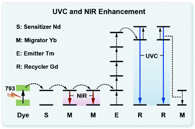 | ||
| Scheme 1 Schematic illustration of the dye-sensitized upconversion and downshifting mechanism for UVC and NIR generation. | ||
Results and discussion
Design of Nd3+-doped nanocrystals
In our study, we designed a heterogeneous core–multishell nanocrystal to suppress interior energy consumption and surface quenching, achieving tunable UVC and NIR emissions. Hexagonal phase NaGdF4:49%Yb,1%Tm was chosen as a core nanocrystal for its ability to render the possibility of UVC emission.22 The first shell layer of NaYF4:20%Yb is optically inert to the excited states of Gd3+ ions and can block the energy transfer from Gd3+ to interior lattice defects. The second shell layer contained a high concentration of Nd3+ ions (90 mol%) for harvesting light. A 793 nm diode laser was selected as the excitation source because the absorption intensity at 793 nm for the nanocrystals is significantly higher than that at 808 nm and 980 nm. The approximate absorption cross-section σ of Nd3+ at 793 nm, 808 nm and 980 nm was calculated to be 4.3 × 10⁻¹⁹ cm2, 1.3 × 10⁻¹⁹ cm2 and 4.3 × 10⁻²⁰ cm2 from the UV-vis absorption spectra of the nanocrystals (Fig. S1†).37Synthesis and characterization of Nd3+-doped GYNY nanocrystals
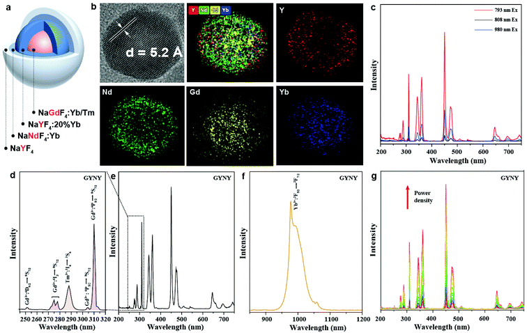
In a typical experiment, we synthesized NaGdF4:49%Yb,1%Tm@NaYF4:20%Yb@NaNdF4:10%Yb@NaYF4 (GYNY) heterogeneous core–multishell nanocrystals via a modified literature method (Fig. 1a).22,38 As shown in Fig. S2,† the size of NaGdF4:49%Yb,1%Tm was found to be 8.6 nm. The transmission electron microscopy (TEM) images show that each shell layer is about 1.5–2.5 nm in thickness and the obtained GYNY nanocrystals are about 21 nm on average. High-resolution TEM (HR-TEM) indicates a single crystalline structure of the as-synthesized GYNY nanocrystals, and the lattice distance of 0.52 nm corresponds to the d spacing for the (100) plane of hexagonal NaYF4 (Fig. 1b). Energy-dispersive X-ray spectroscopy confirms the presence of Nd3+, Gd3+, Yb3+, Y3+ and Tm3+ in these GYNY nanocrystals (Fig. S3†). X-ray powder diffraction (XRD) confirmed the hexagonal phase of the as-prepared nanocrystals (JCPDS file number 16-0334, Fig. S4†). We have also conducted elemental mapping and energy dispersive X-ray (EDX) line scan on the whole particle to demonstrate the spatial distribution of rare-earth cations and the heterogeneous core–shell structure. As shown in Fig. 1b, Nd and Y ions are concentrated in the periphery region, while Gd and Yb show apparently higher concentrations in the central region. The relative concentrations of Nd, Y, Gd and Yb along the scanning path are plotted as shown in Fig. S5.† The result provides more signal counts of Gd and Yb from the central region while those of Nd and Y from the periphery region. Of note is that our nanoparticles do not show a sharp interface at the atomic scale. This result could be ascribed to core–shell intermixing caused by the relatively small core (8.6 nm) and whole core–multishell nanoparticle (20.6 nm), which is consistent with the previous report.39–44We conducted a group of experiments to compare the emission intensity of GYNY nanocrystals under 793 nm, 808 nm and 980 nm excitation. As expected, GYNY nanocrystals under 793 nm excitation showed the strongest emission compared to those under 808 nm and 980 nm excitation (Fig. 1c), which is consistent with our absorption cross-section results of Nd3+ at 793 nm, 808 nm and 980 nm. Similarly, the comparison of the downshifting emission intensities at 793 nm, 808 nm and 980 nm showed the same trend (Fig. S6†).
We next studied the photoluminescence spectrum of the as-synthesized GYNY nanocrystals. As shown in Fig. 1d, obvious upconversion emissions from the 6IJ and 6PJ energy levels of Gd3+ peaked at 273 nm (6IJ → 8S7/2), 276 nm (6IJ → 8S7/2), 279 nm (6IJ → 8S7/2), 306 nm (6P5/2 → 8S7/2) and 311 nm (6P7/2 → 8S7/2) in the UV region were observed under 793 nm excitation. A small peak at 253 nm from the 6DJ energy levels of Gd3+ demonstrated a six-photon upconversion process, which could be attributed to the 6D9/2 → 8S7/2 optical transition.45–47 Meanwhile, we observed an intense downshifting emission peaked at 980 nm (2F5/2 → 2F7/2) from Yb3+ due to the efficient energy transfer from Nd3+ to Yb3+ in GYNY nanocrystals (Fig. 1f). We further investigated the excitation-power-dependent upconversion emission spectra of GYNY nanoparticles under 793 nm excitation (Fig. 1g). Taken together, photoluminescence investigation revealed that a collection of lanthanide ions including Gd3+, Tm3+, Nd3+ and Yb3+ can work together to generate upconversion emissions spanning the UVC and NIR spectral region from 250 to 1200 nm.
The generation of a broad emission profile spanning the whole UV to NIR spectral region is important for expanding the scope of lanthanide-based nanocrystals in favor of diverse applications in bioimaging, molecular sensing, therapy, and security printing. Therefore, on the basis of this nanocrystal design strategy, we further broaden the spectrum of lanthanide-based nanocrystals by simply doping Yb and Er in the third shell layer. We prepared NaGdF4:49%Yb,1%Tm@NaYF4:20%Yb@NaNdF4:10%Yb@NaYF4:20%Yb,2%Er@NaYF4 (GYNY20%Yb,2%ErY) nanocrystals by the same synthesis route except for the use of the third shell stock solution of NaYF4:Yb,Er. Significantly, the luminescence spectrum of the samples could extend to 1600 nm (Fig. 2).
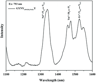 | ||
| Fig. 2 Downshifting emission spectrum of NaGdF4:49%Yb,1%Tm@NaYF4:20%Yb@NaNdF4:10%Yb@NaYF4:20%Yb,2%Er@NaYF4 nanocrystals. | ||
Optimization of dopant concentration
To achieve the required strong emission in both the UVC and NIR regions in a nanocrystal, we synthesized a series of NaGdF4@NaYF4@NaNdF4@NaYF4 core–multishell nanocrystals with varying contents of Yb3+ and Nd3+. The second shell layer was doped with different concentrations of Yb3+ (0–50 mol%), while it had a fixed Nd3+ dopant concentration of 50 mol% (Fig. S7a and S8†). We then fixed the Yb3+ dopant concentration of 10 mol% and changed the concentration of Nd3+ from 1 mol% to 90 mol% in the second shell layer (Fig. S7b and S9†). Taking into account the UVC upconversion and downshifting emission intensity, we determined the optimal Yb3+ and Nd3+ concentration to be 10 and 90 mol%, respectively (Fig. S7b and S7c†).The role of the NaYF4 interlayer in GYNY nanocrystals
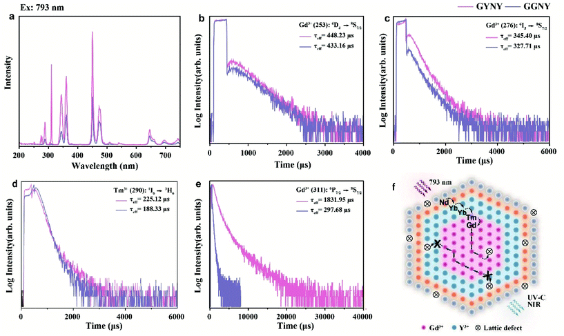
To verify the role of the NaYF4-based first layer in realizing UVC upconversion emission, we synthesized a pair of GYNY and NaGdF4:49%Yb,1%Tm@NaGdF4:20%Yb@NaNdF4:10%Yb@NaYF4 (GGNY) nanocrystals. After replacing the interlayer of NaYF4 with NaGdF4, the upconversion emissions from 6DJ, 6IJ, and 6PJ in the UV region were significantly quenched either under 793 nm or 980 nm excitation (Fig. 3a and S10†). We then compared the excited state lifetime of Gd3+. As shown in Fig. 3b–e, a significantly prolonged Gd3+ lifetime (6P7/2 level, ∼6 times) was observed when the NaYF4 first layer was applied. In stark contrast, the Gd3+ lifetimes for emissions from the 6DJ and 6IJ energy levels and the Tm3+ lifetimes for emissions from the II6 energy level were essentially unaltered after the use of the NaYF4 first layer. These results indicated that the energy loss from Gd3+ to interior lattice defects was mainly through the 6P7/2 energy level.Of note is that real materials usually contain a high density of lattice defects. An excited Gd3+ ion undergoes two different optical processes: (i) an excited Gd3+ ion transfers its energy to a nearby defect centre and subsequently undergoes nonradiative relaxation; (ii) a resonant energy transfer occurs within the Gd3+ sublattice, followed by radiative relaxation and gives rise to upconversion emission. As shown in Fig. 3f, the NaYF4-based first shell can block the energy transfer from Gd3+ to the interior lattice defects located in the shell regions in our design, promoting the occurrence of fast energy hopping in the Gd3+ sublattice at the core domain, thereby realizing intense UVC upconversion emissions. The NaYF4-based first layer played a critical role in locking in and recycling Gd3+ excitation energy. These results accord with the recently proposed upconverted excitation lock-in (UCEL) mechanism by our group.22
The energy transfer efficiency from Nd3+ to Yb3+
The energy transfer efficiency η from Nd3+ to Yb3+ can be quantitatively estimated from eqn (1) and (2):48,49 | (1) |
 | (2) |
To calculate the Nd3+-to-Yb3+ energy transfer efficiency, we synthesized a pair of nanocrystals of NaGdF4:49%Yb,1%Tm@NaYF4:20%Yb@NaNdF4:10%Yb@NaYF4 (GYNY with Yb3+) and NaGdF4:49%Y,1%Tm@NaYF4@NaNdF4:10%Y@NaYF4 (GYNY without Yb3+) as shown in Fig. S11.† Of note is that the energy acceptor of Yb3+ was replaced by optically inert Y3+ ions to measure the intrinsic lifetime of Nd3+. Under 793 nm pulsed excitation, the lifetime of Nd3+ of the pair of nanocrystals at 893 nm was measured, and the Nd3+-to-Yb3+ energy transfer efficiency was calculated to be 89% (Fig. 4), which is slightly higher than the previous reports.50
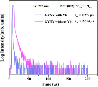 | ||
| Fig. 4 Luminescence decay curves of Nd3+ emissions measured at 893 nm for GYNY with and without Yb3+ nanocrystals by pulsed 793 nm excitation. | ||
Dye sensitization for upconversion and downshifting luminescence enhancement
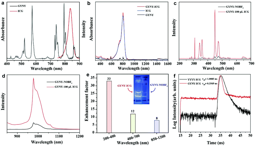
For efficient dye sensitization, the absorption wavelength of the lanthanide-based nanocrystals should overlap with the dye fluorescence to achieve an efficient energy transfer from the dye to nanocrystals. Herein, indocyanine green (ICG) was chosen for NIR dye sensitization due to its large absorption cross-section (∼6 × 10⁻¹⁶ cm2), which is about 1500 times higher than that of Nd3+ at 793 nm (∼4 × 10⁻¹⁹). The absorption curve of ICG was recorded using a UV–vis spectrophotometer. As shown in Fig. 5a, a good spectral overlap between the absorption band of GYNY and the fluorescence of ICG was observed, providing an important prerequisite for efficient non-radiative energy transfer from ICG to GYNY nanocrystals.51We next investigated the optical behavior of GYNY nanocrystals sensitized by the ICG dye of different concentrations. To ensure close contact between nanocrystals and ICG, the original oleic acid ligand capped on the surface of GYNY was replaced by the ionic NOBF4 ligand, and then the ICG dye was coated onto the surface of nanocrystals.52 The removal of oleic acid and the surface capping of ICG were confirmed by FTIR analysis (Fig. S12†). After capping ICG on the surface of GYNY, we observed a remarkably enhanced absorption peak of GYNY, which also confirmed the success of ICG coating (Fig. 5b).
Subsequently, we found that the enhancement factor varies with changes in ICG concentration (Fig. S13†). In the tested ICG concentration range, the intensities of upconversion and downshifting emissions of GYNY were all significantly improved, reaching a maximum at the ICG concentration of 100 μL. Specifically, we observed more than 30-fold, 10-fold, and 8-fold enhancements in the range of 200–400 nm of UVC emission, 400–700 nm of visible emission, and 850–1200 nm of NIR emission by dye sensitization (Fig. 5c–e). The enhancement factor of the whole spectrum ranging from 240 to 1200 nm of the as-prepared ICG sensitized-GYNY compared with that of GYNY was estimated to be 8.6-fold. Notably, a higher concentration of ICG induced a small emission enhancement factor, which is possibly due to the dye–dye quenching interaction on the surface of GYNY.52 The photograph of ICG sensitized-GYNY showed an obviously increased brightness, providing direct evidence of effective ICG sensitization for Nd3+-doped nanocrystals under 793 nm excitation (Fig. 5e, insert).
We also extended the strategy by coating the ICG dye on a novel nanoparticle structure, NaGdF4:49%Yb,1%Tm@NaYF4:20%Yb@NaNdF4:10%Yb@NaYF4:20%Yb,2%Er@NaYF4 (GYNY20%Yb,2%ErY). The results showed that the luminescence intensity of Tm upconversion and Er downshifting can be enhanced simultaneously under 793 nm excitation. We observed about 2.4-fold and 2.1-fold enhancements in the range of 200–700 nm and 1250–1600 nm by dye sensitization, respectively (Fig. S14†).
Notably, ICG is a tricarbocyanine and fluorescent dye, which will undergo photodegradation and thermal degradation under certain conditions.53,54 We studied the photostability of GYNY@ICG under excitation at 793 nm. The emission spectra of GYNY@ICG were obtained every 2 min at a power density of 20 W cm−2. Fig. S15† shows that the Förster resonance energy transfer (FRET) effect between the dye and Nd decreased with a prolonged illumination time and disappeared at about 20 min.
Moreover, we conducted a quantitative study for the quantum yields (QYs) of GYNY and GYNY@ICG nanoparticles. We measured the QYs of upconversion emission in the range of 200–400 nm of the as-prepared GYNY and GYNY@ICG nanoparticles, and the results were recorded to be approximately 0.04% and 0.14%, respectively. Besides, the QYs of GYNY and GYNY@ICG nanoparticles were approximately 0.45% and 0.63% from 400 to 750 nm, 0.49% and 0.87% from 200 to 750 nm, and 14.88% and 14.97% from 820 to 1400 nm, respectively.
We then obtained the fluorescence decay curves of the ICG emission at 830 nm under 270 nm excitation. As shown in Fig. 5f, the decay lifetimes of the ICG dye with and without the presence of GYNY nanocrystals were determined to be 0.3569 ns and 1.0085 ns, respectively, suggesting an energy transfer efficiency of 64.6%. This result also demonstrated a Förster resonance energy transfer mechanism from ICG to Nd3+ ions doped in the nanocrystals.55
In our study, the critical distance from the dye to the Nd ions was determined by adjusting the thickness of the outermost NaYF4 layer to 2.3 nm (GYNY), 4.8 nm (GYNYY) and 6.7 nm (GYNYYY), respectively (Fig. S16†). Then, the materials with a concentration of 5 mg mL−1 were coated with the ICG dye (100 μL, 0.1 mg mL−1), respectively. We compared the upconversion luminescence intensity of the nanoparticles with different thicknesses of the NaYF4 layer before and after coating with the dye (Fig. S16†). When the thickness of the outermost NaYF4 layer was 4.8 nm, the emission intensity was almost unchanged after coating with the ICG dye in the range of 200–700 nm, respectively. However, when the thickness of the outermost NaYF4 layer was 6.7 nm, the emission intensity decreased after coating with the ICG dye. These results showed that the critical distance between the ICG dye and Nd is about 5 nm.
In addition, we also investigated whether the triplet state of ICG is involved in the energy transfer between Gd. Herein, we designed a new nanostructure of GYN@Y30Gd by doping 30% Gd in the outermost NaYF4 shell. After coating ICG onto the surface of GYN@Y30Gd and GYNY, we compared their luminescence intensities before and after ICG dye coating. The results indicated that the emission intensity of GYNY and GYN@Y30Gd from 200 to 400 nm was enhanced by about 4 and 2 times, and that from 850 to 1200 nm was enhanced by about 2-fold and 3-fold, respectively (Fig. S17a–d†). This enhancement effect was negligible compared with the huge enhancement in the triplet state of ICG involved energy transfer in the previous report.56 Moreover, there is no significant difference in the lifetimes of Gd3+ (311 nm) in GYNY and GYN@Y30Gd nanoparticles before and after ICG coating (Fig. S17e†). Therefore, we can infer that there is no energy transfer between the triplet state of the ICG dye and Gd.
Considering its potential in in vivo and in vitro biological applications, it is essential to achieve high-efficiency dye-sensitized upconversion and downshifting luminescence in aqueous solutions.52 We connect ICG to the surface of GYNY nanocrystals through the amphiphilic molecule DSPE-PEG-COOH and further optimize the amount of ICG, thereby obtaining the most effective ICG-sensitized GYNY nanocrystals. As shown in Fig. S18,† the ICG-sensitized GYNY nanocrystals showed the optimal (about 2-fold) enhancement in the entire spectrum ranging from 240 to 1200 nm at an ICG concentration of 3 μg mL−1.
Mechanistic investigation of dye-sensitized Nd3+-doped nanocrystals with enhanced UVC and NIR emission
Fig. 6 shows a typical upconversion and downshifting process in the ICG-sensitized heterogeneous core–multishell nanocrystals upon 793 nm excitation. ICG can harvest light in a broad range from 700–860 nm, enabling a wide spectral excitation. Then, the harvested energy is transferred to Nd3+ in the 4F5/2 energy state in nanocrystals non-radiatively via the FRET mechanism. The triplet state of ICG involved in the energy transfer mechanism is not observed under our examined experimental conditions. After quickly relaxing to the 4F3/2 energy state of Nd3+ ions, Yb3+ ions act as an energy migrator to capture the energy from Nd3+, inducing NIR emission peaked at 980 nm. Meanwhile, partial energy was transferred to Tm3+ in the 3P2 state via a five-photon upconversion process. The excitation energy in the 3P2 state then relaxes non-radiatively to the 1I6 state and generates UV emission at 290 nm. The energy transfer from Tm3+ to Gd3+ successfully promotes the 6PJ energy state of Gd3+ and gives rise to UV emission at 311 nm through the EMU mechanism.15 Subsequently, with the assistance of Yb3+ ions, the 6DJ state of Gd3+ is further populated due to the appropriate energy matching of the following optical transitions of Yb3+ (2F5/2 → 2F7/2, 9750 cm−1) and Gd3+ (6PJ → 6DJ, 8750 cm−1) via a six-photon upconversion process.45–47 Thus, UVC upconversion emission peaked at 253, 273, 276, and 279 nm from 6DJ and 6IJ of Gd3+ can be obtained. Of note is that Gd3+–Gd3+ energy migration features a long travel distance, which can be terminated by the interior lattice defects in the Gd3+-based homogeneous core–shell structures. In our design, the NaYF4-based first shell layer played a vital role in selectively blocking the energy transfer from Gd3+ to interior lattice defects, which preserves the excitation energy within the core domain, induces increased populations of the 6DJ, 6IJ, and 6PJ energy states of Gd3+, and finally generates intense UVC emissions from Gd3+ ions.22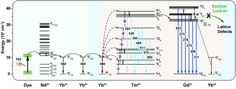 | ||
| Fig. 6 Schematic energy diagram of the cascade energy transfer within a dye-sensitized heterogeneously doped-lanthanide nanocrystal. | ||
Potential in enhancing reactive oxygen species (ROS) generation
Due to its photosensitivity, ICG can be used to produce singlet oxygen (1O2) in photodynamic therapy (PDT) to destroy cancer cells.57,58 The ability to generate singlet oxygen (1O2) of ICG-coated GYNY nanocrystals was evaluated using the 1,3-diphenylisobenzofuran (DPBF) chemical probe under 793 nm laser irradiation.59 The characteristic absorbance of DPBF gradually decreased with irradiation time, indicating the successful production of 1O2 (Fig. S19†). These results indicate the potential applications of NIR light mediated photosensitizing nanocrystals for ROS generation in photocatalysis and biomedical fields.Conclusions
In summary, we developed dye-sensitized heterogeneous core–multishell lanthanide nanocrystals to regulate the energy transfer pathway for UVC and NIR enhancement upon 793 nm excitation. The heterogeneous nanostructural design with optimized lanthanide doping efficiently suppresses the energy loss trapped by interior energy traps and promotes efficient energy transfer from Nd3+ to Yb3+, thus promoting upconverted UVC emission and intense downshifting NIR emission. The multistep cascade sensitization of NIR excitation allows for maximized energy trapping by lanthanide ions, thus permitting enhanced upconversion and downshifting emission from the UVC to NIR region. We believe that this study will advance the design rationale for broadening the emission profile of lanthanides and enhancing the NIR dye-sensitized UVC to NIR emission. This study will also benefit the future development of novel lanthanide nanocrystals for applications in biomedicine, photocatalysis, environmental science, and many other emerging fields.Experimental section
Materials, details on nanocrystal synthesis and characterization are included in the ESI.†Author contributions
Q. S. planned the project. Y. L., M. Z., M.-T. Z., and H.-L. W. performed the experiments. Q. S., Y. L., M. Z., and Y. S. designed the experiments and analysed the data. Q. S., Y. L. and M. Z. wrote the paper and prepared the figures. All authors discussed the results and revised the manuscript.Conflicts of interest
There are no conflicts to declare.Acknowledgements
The authors thank the National Natural Science Foundation of China (no. 21701109).Notes and references
- Q. Su, W. Feng, D. Yang and F. Li, Acc. Chem. Res., 2017, 50, 32–40 CrossRef CAS PubMed.
- M. Ang, J. Yoon, M. Zhou, H. Wei, Y. Goh, Z. Li, J. Feng, H. Wang, Q. Su, D. Ong and X. Liu, Adv. Mater., 2022, 34, 2106194 CrossRef CAS PubMed.
- X. Zhu, Q. Su, W. Feng and F. Li, Chem. Soc. Rev., 2017, 46, 1025–1039 RSC.
- D. Yang, P. Ma, Z. Hou, Z. Cheng, C. Li and J. Lin, Chem. Soc. Rev., 2015, 44, 1416–1448 RSC.
- F. Wang and X. Liu, Chem. Soc. Rev., 2009, 38, 976–989 RSC.
- S. Wang, L. Liu, Y. Fan, A. M. El-Toni, M. S. Alhoshan, D. Li and F. Zhang, Nano Lett., 2019, 19, 2418–2427 CrossRef CAS PubMed.
- L. Wang, H. Zhou, J. Hu, B. Huang, M. Sun, B. Dong, G. Zheng, Y. Huang, Y. Chen, L. Li, Z. Xu, N. Li, Z. Liu, Q. Chen, L.-D. Sun and C.-H. Yan, Science, 2019, 363, 265–270 CrossRef CAS PubMed.
- Y. Ma, J. Bao, Y. Zhang, Z. Li, X. Zhou, C. Wan, L. Huang, Y. Zhao, G. Han and T. Xue, Cell, 2019, 117, 243–255 CrossRef PubMed.
- Z. Li, H. Yuan, W. Yuan, Q. Su and F. Li, Coord. Chem. Rev., 2018, 354, 155–168 CrossRef CAS.
- Z. Gong, W. Zheng, Y. Gao, P. Huang, D. Tu, R. Li, J. Wei, W. Zhang, Y. Zhang and X. Chen, Angew. Chem., Int. Ed., 2019, 58, 6943–6947 CrossRef CAS PubMed.
- D. Tu, W. Zheng, P. Huang and X. Chen, Coord. Chem. Rev., 2019, 378, 104–120 CrossRef CAS.
- W. Zheng, P. Huang, Z. Gong, D. Tu, J. Xu, Q. Zou, R. Li, W. You, J.-C. G. Bünzli and X. Chen, Nat. Commun., 2018, 9, 3462 CrossRef PubMed.
- W. Zheng, P. Huang, D. Tu, E. Ma, H. Zhu and X. Chen, Chem. Soc. Rev., 2015, 44, 1379–1415 RSC.
- J. Zhou, Q. Liu, W. Feng, Y. Sun and F. Li, Chem. Rev., 2015, 115, 395–465 CrossRef CAS PubMed.
- F. Wang, R. Deng, J. Wang, Q. Wang, Y. Han, H. Zhu, X. Chen and X. Liu, Nat. Mater., 2011, 10, 968–973 CrossRef CAS PubMed.
- B. Zhou, W. Yang, S. Han, Q. Sun and X. Liu, Adv. Mater., 2015, 27, 6208–6212 CrossRef CAS PubMed.
- S. Fischer, C. Siefe, D. F. Swearer, C. A. McLellan, A. P. Alivisatos and J. A. Dionne, Angew. Chem., Int. Ed., 2020, 59, 21603–21612 CrossRef CAS PubMed.
- H. Dong, L. D. Sun and C. H. Yan, J. Am. Chem. Soc., 2021, 143, 20546–20561 CrossRef CAS PubMed.
- Q. Chen, X. Xie, B. Huang, L. Liang, S. Han, Z. Yi, Y. Wang, Y. Li, D. Fan, L. Huang and X. Liu, Angew. Chem., Int. Ed., 2017, 56, 7605–7609 CrossRef CAS PubMed.
- T. A. Shakhverdov, Opt. Spectrosc., 2003, 95, 571–580 CrossRef CAS.
- B. Chen and F. Wang, Acc. Chem. Res., 2020, 53, 358–367 CrossRef CAS PubMed.
- Q. Su, H. L. Wei, Y. Liu, C. Chen, M. Guan, S. Wang, Y. Su, H. Wang, Z. Chen and D. Jin, Nat. Commun., 2021, 12, 4367 CrossRef CAS PubMed.
- Q.-C. Sun, H. Mundoor, J. C. Ribot, V. Singh, I. I. Smalyukh and P. Nagpal, Nano Lett., 2014, 14, 101–106 CrossRef CAS PubMed.
- Y. Fan and F. Zhang, Adv. Opt. Mater., 2019, 7, 1801417 CrossRef.
- Y. Li, S. Zeng and J. Hao, ACS Nano, 2019, 13, 248–259 CrossRef CAS PubMed.
- L. Liu, S. Wang, B. Zhao, P. Pei, Y. Fan, X. Li and F. Zhang, Angew. Chem., Int. Ed., 2018, 57, 7518–7522 CrossRef CAS PubMed.
- Y. L, M. Jiang, Z. Xue and S. Zeng, Theranostics, 2020, 10, 6875–6885 CrossRef PubMed.
- S. He, J. Song, J. Qu and Z. Cheng, Chem. Soc. Rev., 2018, 47, 4258–4278 RSC.
- J. Xu, A. Gulzar, P. Yang, H. Bi, D. Yang, S. Gai, F. He, J. Lin, B. Xing and D. Jin, Coord. Chem. Rev., 2019, 381, 104–134 CrossRef CAS.
- B. Zhou, L. Yan, J. Huang, X. Liu, L. Tao and Q. Zhang, Nat. Photonics, 2020, 14, 760–766 CrossRef CAS.
- K. L. Reddy, R. Balaji, A. Kumar and V. Krishnan, Small, 2018, 14, 1801304 CrossRef PubMed.
- I. E. Kolesnikov, A. A. Kalinichev, M. A. Kurochkin, E. V. Golyeva, E. Y. Kolesnikov, A. V. Kurochkin, E. Lahderanta and M. D. Mikhailov, Sci. Rep., 2017, 7, 18002 CrossRef CAS PubMed.
- N. Venkatachalam, T. Yamano, E. Hemmer, H. Hyodo, H. Kishimoto and K. Soga, J. Am. Ceram. Soc., 2013, 96, 2759–2765 CrossRef CAS.
- Y. Zhong, Z. Ma, S. Zhu, J. Yue, M. Zhang, A. L. Antaris, J. Yuan, R. Cui, H. Wan, Y. Zhou, W. Wang, N. F. Huang, J. Luo, Z. Hu and H. Dai, Nat. Commun., 2017, 8, 737 CrossRef PubMed.
- H. Zhang, Y. Fan, P. Pei, C. Sun, L. Lu and F. Zhang, Angew. Chem., Int. Ed., 2019, 58, 10153–10157 CrossRef CAS PubMed.
- H. Li, X. Wang, T. Y. Ohulchanskyy and G. Chen, Adv. Mater., 2021, 33, 2000678 CrossRef CAS PubMed.
- Y. Xu, X. Gong, Y. Chen, M. Huang, Z. Luo and Y. Huang, J. Cryst. Growth, 2003, 252, 241–245 CrossRef CAS.
- S. Wang, B. Shen, H. L. Wei, Z. Liu, Z. Chen, Y. Zhang, Y. Su, J. Z. Zhang, H. Wang and Q. Su, Nanoscale, 2019, 11, 10220–10228 RSC.
- D. Hudry, A. D. Backer, R. Popescu, D. Busko, I. A. Howard, S. Bals, Y. Zhang, A. Pedrazo-Tardajos, S. V. Aert, D. Gerthsen, T. Altantzis and B. S. Richards, Small, 2021, 17, 2104441 CrossRef CAS PubMed.
- D. Hudry, R. Popescu, D. Busko, M. Diaz-Lopez, M. Abeykoon, P. Bordet, D. Gerthsen, I. A. Howard and B. S. Richards, J. Mater. Chem. C, 2019, 7, 1164–1172 RSC.
- D. Hudry, I. A. Howard, R. Popescu, D. Gerthsen and B. S. Richards, Adv. Mater., 2019, 31, 1900623 CrossRef PubMed.
- D. Hudry, D. Busko, R. Popescu, D. Gerthsen, I. A. Howard and B. S. Richards, J. Mater. Chem. C, 2019, 7, 7371–7377 RSC.
- L. Liu, X. Li, Y. Fan, C. Wang, A. M. El-Toni, M. S. Alhoshan, D. Zhao and F. Zhang, Chem. Mater., 2019, 31, 5608–5615 CrossRef CAS.
- P. U. Bastian, S. Nacak, V. Roddatis and M. U. Kumke, J. Phys. Chem. C, 2020, 124, 11229–11238 CrossRef CAS.
- W.-P. Qin, C.-Y. Cao, L.-L. Wang, J.-S. Zhang, D.-S. Zhang, K.-Z. Zheng, Y. Wang, G.-D. Wei, G.-F. Wang, P.-F. Zhu and R.-J. Kim, Opt. Lett., 2008, 33, 2167–2169 CrossRef CAS PubMed.
- K. Zheng, W. Qin, C. Cao, D. Zhao and L. Wang, J. Phys. Chem. Lett., 2015, 6, 556–560 CrossRef CAS PubMed.
- W.-P. Qin, Z.-Y. Liu, C.-N. Sin, C.-F. Wu, G.-S. Qin, Z. Chen and K.-Z. Zheng, Light: Sci. Appl., 2014, 3, e193 CrossRef CAS.
- M. J. Weber, Phys. Rev. B: Solid State, 1971, 4, 3153–3159 CrossRef.
- K. Bartosiewicz, V. Babin, K. Kamada, A. Yoshikawa and M. Nikl, J. Lumin., 2015, 166, 177–122 CrossRef.
- R. Balda, J. I. Peña, M. A. Arriandiaga and J. Fernández, Opt. Express, 2010, 18, 13842–13850 CrossRef CAS PubMed.
- W. Wei, G. Chen, A. Baev, G. S. He, W. Shao, J. Damasco and P. N. Prasad, J. Am. Chem. Soc., 2016, 138, 15130–15133 CrossRef CAS PubMed.
- W. Shao, G. Chen, A. Kuzmin, H. L. Kutscher, A. Pliss, T. Y. Ohulchanskyy and P. N. Prasad, J. Am. Chem. Soc., 2016, 138, 16192–16195 CrossRef CAS PubMed.
- W. Holzer, M. Mauerer, A. Penzkofer, R.-M. Szeimies, C. Abels, M. Landthaler and W. Bäumler, J. Photochem. Photobiol., B, 1998, 47, 155–164 CrossRef CAS.
- V. Saxena, M. Sadoqi and J. Shao, J. Photochem. Photobiol., B, 2004, 74, 29–38 CrossRef CAS PubMed.
- V. Muhr, C. Würth, M. Kraft, M. Buchner, A. J. Baeumner, U. Resch-Genger and T. Hirsch, Anal. Chem., 2017, 89, 4868–4874 CrossRef CAS PubMed.
- D. J. Garfield, N. J. Borys, S. M. Hamed, N. A. Torquato, C. A. Tajon, B. Tian, B. Shevitski, E. S. Barnard, Y. D. Suh, S. Aloni, J. B. Neaton, E. M. Chan, B. E. Cohen and P. J. Schuck, Nat. Photonics, 2018, 12, 402–407 CrossRef CAS.
- D. Dolmans, D. Fukumura and R. Jain, Nat. Rev. Cancer, 2003, 3, 380–387 CrossRef CAS PubMed.
- W. S. Kuo, Y. T. Chang, K. C. Cho, K. C. Chiu, C. H. Lien, C. S. Yeh and S. J. Chen, Biomaterials, 2012, 33, 3270–3278 CrossRef CAS PubMed.
- Z. Hou, Y. Zhang, K. Deng, Y. Chen, X. Li, X. Deng, Z. Cheng, H. Lian, C. Li and J. Lin, ACS Nano, 2015, 9, 2584–2599 CrossRef CAS PubMed.
Footnotes |
| † Electronic supplementary information (ESI) available. See DOI: 10.1039/d1nr07329j |
| ‡ These authors made an equal contribution to this work. |
| This journal is © The Royal Society of Chemistry 2022 |

