Preparation of BCYF0.10–YDC/BCYF0.10–Ni dual-layer hollow fiber membrane for dry reforming of methane and hydrogen purification†
Received
29th April 2023
, Accepted 8th July 2023
First published on 10th July 2023
Abstract
A ceramic hydrogen permeable membrane reactor for dry reforming of methane (DRM) carries out both the reaction and separation process simultaneously, enabling the production of synthesis gas and pure hydrogen, while also mitigating greenhouse gas emissions. In this study, we prepared F-doped Ba0.95Ce0.8Y0.2O3−δF0.10 (BCYF10) and Ce0.8Y0.2O2−δ (YDC) ceramic powders, a BCYF0.10–YDC/BCYF0.10–Ni dual-layer hollow fiber (HF) membrane, and catalysts with different Ni contents. The catalysts were packed outside the BCYF0.10–YDC/BCYF0.10–Ni HF membrane to obtain a catalytic membrane reactor. The results showed that the hydrogen permeation flux of the dual-layer HF membrane was 0.54 mL min−1 cm−2 at 900 °C with a feed gas of 50 vol% H2/He. Steam and CO2 could increase the hydrogen permeation flux. At 950 °C, the conversion of CH4 and CO2 for Ni/BCYF0.10–YDC catalyst with 30 wt% Ni was 74.5% and 87.1%, respectively. The membrane reactor composed of 30 wt% Ni/BCYF0.10–YDC catalyst maintained good reaction and separation stability during continuous operation for 720 min at 900 °C. The CO and H2 selectivities, as well as carbon balance fluctuated around 87.5%, 69.9%, and 89.4%, respectively, indicating the feasibility of constructing a DRM–hydrogen separation coupled membrane reactor for DRM and concurrent separation of hydrogen.
1. Introduction
Methane (CH4) is the primary component of natural gas and a potent greenhouse gas that presents significant challenge due to the difficulty in activating its C–H bond. CH4 can be reacted with steam (CO2), oxygen (O2), or carbon dioxide (CO2) to form syngas consisting of hydrogen (H2) and carbon monoxide (CO), which can be used in Fischer–Tropsch synthesis for conversion to fuels or hydrocarbons.1–4 The feedstocks for dry reforming of methane (DRM) are all greenhouse gases, making DRM reactions an area of global interest.1,5–8 The resultant syngas produced by DRM reaction can be further separated and purified to obtain pure H2 using various techniques including pressure swing adsorption (PSA), cryogenic separation, and membrane separation.9,10 Among these, membrane separation offers distinct advantages of small equipment area, simple operation, low operation costs, and low energy consumption.11,12 H2-permeable membranes made of proton–electron mixed conducting ceramics exhibit high mechanical strength and good thermal and chemical stabilities.9,13,14
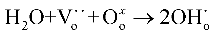
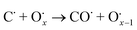
One major obstacle hindering the development of H2-permeable ceramic membranes is their low H2 permeation flux and poor stability in certain atmospheres. To address this issue, researchers have proposed numerous modification strategies such as optimization of material composition, membrane structure, and H2 separation process conditions.9,11,14 For instance, in some proton conductors like Sr1−xCe0.9Yb0.1O3−δ,15 A-site cation defects and oxygen vacancies are formed due to A-site deficiency (eqn (1)):
| |  | (1) |
This method reduces the chemical potential of the A-site alkaline, thus increasing the material's stability and resistance to carbonation. Zhou et al.16 used a solid-phase reaction method to prepare F−, Cl−, and Br−-doped BaCe0.9Gd0.1O3−δ (BCG) chalcogenide oxides. They showed that partial substitution of O by halogens and partial substitution of Ba–O bonds in BCG by Ba–X (X = F, Cl, Br) with low alkalinity gave improved chemical stability of BCG in CO2 atmosphere. Su et al.17 also used the F-doping strategy to improve the CO2 stability of BaCe0.8Sm0.2O3−δF0.10 (BCSF) proton conductor.
Besides doping, another method to optimize the properties of the composite material is the addition of a secondary phase material.18 Zhuang et al.19 used a solid-phase reaction method and dry-pressing method to prepare Ni–BaCe0.85Fe0.15O3−δ (Ni–BCF) metal–ceramic dual-phase membranes. Ni acted as the electron-conducting phase to enhance the electronic conductivity and surface exchange reaction rate of the membrane. However, the difference in expansion coefficients between metal and ceramic reduced the thermomechanical stability and the desired densification of metal–ceramic composite membranes.20 Furthermore, interactions between metals and ceramics also occurred at high temperatures, making the preparation of metal–ceramic composite membranes challenging.21,22
The electronic conductivity and thermal expansion between the electron-conducting phase and proton-conducting phase of a dual-phase composite membrane can be improved by selecting a ceramic phase with good electronic conductivity as the second phase. Furthermore, the preparation process of ceramic dual-phase membranes does not require inert or reducing gas protection, making it simpler and more cost-effective.23 In the work of Liu et al.,24 BaCe0.8Y0.2O3−δ–Ce0.8Y0.2O2−δ (BCY–YDC) dual-phase composite membranes were prepared by solid-state method, and only a small amount of BaCO3 was produced after the CO2 stability test, whereas pure BCY decomposed entirely to BaCO3. Mortalò et al.25 confirmed the chemical stability of BaCe0.65Zr0.20Y0.15O3−δ–Ce0.85Gd0.15O2−δ ceramic–ceramic dual-phase membranes under 700 ppm H2S atmosphere.
The H2 permeation flux and stability of membranes can also be improved by establishing an asymmetric structure with independent distribution of proton–electron conducting phases, porous support layers, and ultrathin dense layers.26–30 The H2 permeation process of ceramic H2 permeation membrane is mainly controlled by bulk diffusion and surface exchange reactions, and the reduction of membrane thickness and modification to the surface structure can enhance the H2 permeation flux of ceramic membranes. Hollow fiber (HF) membranes are easier to seal at their ends and provide greater effective membrane area per unit volume at a thickness of about 200 μm compared to flat membranes.31–36 Therefore, the co-spinning-co-sintering technique is preferable for the production of multiphase dual-layer HF membranes with thin dense layers, and the combination of reduced membrane thickness and increased surface reaction rate can effectively improve the H2 permeation performance of ceramic membranes.29,31,32,34,37–40
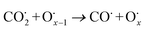
The use of non-precious metal Ni as a catalyst for DRM reactions has been widely adopted, but the catalyst surface is prone to carbon accumulation and deactivation at high temperatures. To overcome this limitation, several strategies have been reported, such as bimetallic synergistic effects, formation of lattice oxygen, and modification of catalyst preparation methods.5,6,41 BaCeO3 or CeO2-based oxides have certain oxygen ion conductivity, which can promote the activation of CH4 and CO2 by releasing lattice oxygen (eqn (2) and (3)), which can also react with carbon accumulated on the catalyst surface (eqn (4) and (5)), thereby alleviating catalyst deactivation.5,42–46 BaCeO3-based oxide is a basic material that can promote the adsorption dissociation of weakly acidic CO2 and the oxidation of accumulated carbon.
| | | CeO2 + nCH4 → CeO2−n + nCO + 2nH2 | (2) |
| | | CeO2−n + nCO2 → CeO2 + nCO | (3) |
| |  | (4) |
| |  | (5) |
In this work, we selected Ba0.95Ce0.8Y0.2O3−δ as the base material for its high proton conductivity, and utilized an anionic F-doping strategy to further enhance its conductivity. We prepared a Ba0.95Ce0.8Y0.2O3−δF0.10–Ce0.8Y0.2O2−δ/Ba0.95Ce0.8Y0.2O3−δF0.10–Ni (BCYF0.10–YDC/BCYF0.10–Ni) dual-layer asymmetric HF dense ceramic H2 permeable membrane using a co-spinning-co-sintering technique. The catalysts were prepared with different Ni contents using the mechanical mixing method, and the catalytic membrane reactor was assembled by packing catalysts outside the BCYF0.10–YDC/BCYF0.10–Ni HF membrane. We characterized the phase composition, microscopic morphology, and thermal expansion of the powders using powder X-ray diffraction (XRD), scanning electron microscopy (SEM), energy dispersive spectroscopy (EDS), and dilatometry (DIL), and investigated the DRM and H2 separation performance of the membrane reactor. Overall, this work serves to investigate the combined functionality of Ba0.95Ce0.8Y0.2O3−δ-based membrane and catalytic reactor for DRM.
2. Experimental
2.1. Preparation of ceramic oxides, catalysts and HF membrane
The BCYF0.10 and YDC powder were prepared by sol–gel method:47,48
(1) The required amount of metal nitrate, citric acid, and EDTA were added sequentially to deionized water under heating and stirring (the ratio of total metal ions![[thin space (1/6-em)]](https://www.rsc.org/images/entities/char_2009.gif) :citric acid:EDTA was 1:1.44:1.2), with the typical experimental parameters shown in Table 1.
:citric acid:EDTA was 1:1.44:1.2), with the typical experimental parameters shown in Table 1.
Table 1 Composition of raw materials required for the preparation of 0.1 mol BCYF0.10 powder
| Materials |
Quantity/mol |
Quantity/g |
| Ba(NO3)2 |
0.09 |
23.52 |
| Ce(NO3)3·6H2O |
0.08 |
34.73 |
| Y(NO3)3·6H2O |
0.02 |
7.66 |
| BaF2 |
0.005 |
0.88 |
| EDTA |
0.23 |
53.80 |
| Citric acid |
0.28 |
67.22 |
(2) The mixture was heated and stirred continuously until the gel was formed. An appropriate amount of ammonium nitrate was then dissolved in the gel, which was transferred to a hotplate. Upon heating to 350 °C, spontaneous combustion occurred and the powder precursors were obtained.
(3) The powder precursors were ball milled for 5–8 min and then calcined at 1150 °C in air atmosphere for 5 h. The BCYF0.10:YDC mixture (BCYF0.10–YDC) with a mass ratio of 1:2.5 was ball milled for 24 h in a planetary ball mill using ethanol as dispersant, then dried, and finally sieved with a 200-mesh sieve. Using the same method, BCYF0.10–NiO composite powder with BCYF0.10:NiO mass ratio of 9:10 was prepared.
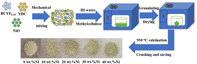
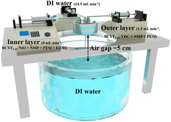
The DRM catalysts were prepared by mechanical mixing method (as shown in Fig. 1). NiO and BCYF–YDC powders with different mass ratios were ball-milled for 5 h by adding alcohol as dispersant. After granulating, drying, calcination, crushing and sieving, catalysts with different Ni content were obtained. The BCYF0.10–YDC/BCYF0.10–Ni dual-layer asymmetric HF membrane was prepared by the co-spinning-co-sintering method as previously reported elsewhere.28,36 The BCYF0.10–YDC and BCYF0.10–NiO solutions were used as outer and inner layer casting solution, respectively. The specific steps were as follows: dried PESf was added to NMP under stirring until a transparent solution was formed. The dried BCYF0.10–YDC powder was then added to the above solution in batches under stirring until a well-mixed casting solution (outer layer) was formed. Using the same method, the casting solution (inner layer) with the powder composition of BCYF0.10–NiO was prepared, to which 6 wt% EtOH was added as the pore-forming agent to regulate the viscosity of the casting solution. After continuously stirring for 48 h and degassing for 1.5 h, the casting solution was then spun in a homemade device as shown in Fig. 2. Deionized water/tap water was used as the inner/outer coagulant, respectively, and the flow rate of the inner and outer casting solution and the inner coagulant was regulated using a syringe pump. The typical experimental parameters are shown in Table 2. The ceramic HF precursors were cut, dried, and placed in a chamber-type high-temperature furnace, ramped up to 1500–1600 °C at a heating rate of 2–3 °C min−1, sintered for 5 h, and then cooled down to room temperature at a cooling rate of 2–3 °C min−1 to obtain BCYF0.10–YDC/BCYF0.10–NiO dual-layer asymmetric HF ceramic membrane. Finally, NiO in the porous support inner layer was reduced with H2 to obtain BCYF0.10–YDC/BCYF0.10–Ni ceramic membrane.
 |
| | Fig. 1 Schematic diagram of the catalyst particle preparation process. | |
 |
| | Fig. 2 Schematic illustration of HF membrane precursors prepared by co-spinning method. | |
Table 2 Parameters for the preparation of dual-layer HF membrane precursors by co-spinning method
|
|
Outer layer/wt% |
Inner layer/wt% |
| BCYF0.10–YDC |
44 |
0 |
| BCYF0.10–NiO |
0 |
59.8 |
|
N-Methyl-2-pyrrolidone (NMP) |
44 |
25.6 |
| Polyethersulfone (PESf) |
12 |
8.6 |
| Ethanol (EtOH) |
0 |
6 |
| Spinning speed (mL min−1) |
1.5 |
8 |
| Air gap (cm) |
5 |
| Internal coagulation bath flow rate (mL min−1) |
DI water, 14.5 |
| External coagulation bath |
DI water |
2.2. Characterization
An X-ray diffractometer (Bruker D8 Advance, Germany) was used to analyze the phase composition of ceramic powders using a scanning range of 20–80° and a scanning rate of 8° min−1. The current and voltage were set to 30 mA and 40 kV, respectively. The microstructure and elemental distribution of BCYF powder and BCYF0.10–YDC/BCYF0.10–Ni dual-layer hollow fiber membrane were characterized using a scanning electron microscope (COXEM EM-30N, South Korea) equipped with an X-ray energy dispersive spectroscopy (EDS) instrument (AZtecOne, USA). The samples were sputtered with gold prior to the SEM tests to improve the electrical conductivity of the samples.
The BCYF0.10–YDC and BCYF0.10–NiO powders were pressed into 30 mm × 8 mm × 4 mm bars using a tablet press and sintered in a high-temperature furnace at 1600 °C for 5 h to form a dense body. The thermal expansion properties of the samples were measured in air by a dilatometer (Netzsch DIL 402PC, Germany) between 35 and 1000 °C using a heating rate of 3 °C min−1.
2.3. H2 permeation and DRM performance
The H2 permeation performance of the BCYF0.10–YDC/BCYF0.10–Ni dual-layer HF membrane was tested using a homemade device. Prior to the test, NiO was reduced to Ni by feeding 100 mL min−1 of 50 vol% H2/He mixture at 600 °C into the fiber lumen while 100 mL min−1 of N2 sweep gas was introduced into the shell side. The gas flow rates were controlled using mass flow controllers, which were calibrated by a soap bubble flow meter. The gas composition was analyzed by gas chromatography (GC, Agilent 6890N, USA) with a 5 Å molecular sieve column (4 m × Φ3 mm), and high-purity argon was used as the carrier gas. When N2 was used as the sweep gas, the H2 permeation flux was calculated by eqn (6):| |  | (6) |
When a CO2/N2 mixture is used as the sweep gas, the H2 permeation flux was calculated by eqn (7):
| |  | (7) |
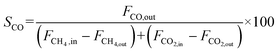
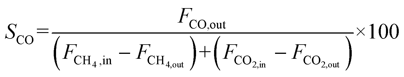
The CO2 conversion and CO yield were calculated by eqn (8) and (9), respectively:
| |  | (8) |
| |  | (9) |
where
JH2 was the H
2 permeation flux, mL min
−1 cm
−2;
F was the feed gas flow rate, mL min
−1;
CH2,
CHe, and
CCO were the volume percentages of H
2, He and CO in the tail gas of shell side and HF lumen, respectively, vol%;
X was the volume ratio of H
2/He in feed gas;
A was the effective membrane area, cm
2,
XCO2 and
YCO were the CO
2 conversion and CO yield, %, respectively;
FCO,in,
FCO2,in and
FCO2,out were the CO flow rate after reaction, the CO
2 flow rate before reaction and the CO
2 flow rate after reaction, respectively, in mL min
−1.
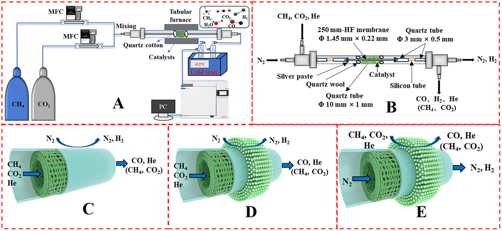
The catalyst performance was tested in a quartz tube fixed-bed reactor with an inner diameter of 8 mm, the test setup of which is shown in Fig. 3A. 0.5 g catalysts were packed in the middle of the reactor with a packing length of 12 mm. Before the reaction, the catalysts were reduced by 30 mL min−1 H2 at 600 °C for 1 h. The temperature was then increased to 700 °C and 50 mL min−1 CH4 and 50 mL min−1 CO2 were introduced, after stabilizing for 35–50 min the samples were analyzed by GC. The CH4 and CO2 conversions, H2/CO molar ratio, and carbon balance were calculated by eqn (8) and the following eqn (10)–(14):
| |  | (10) |
| |  | (11) |
| |  | (12) |
| |  | (13) |
| | 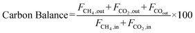 | (14) |
where
X and
S were the conversion and selectivity, respectively, and
Fin and
Fout were the gas flow rates in the feed gas and tail gas, respectively, mL min
−1.
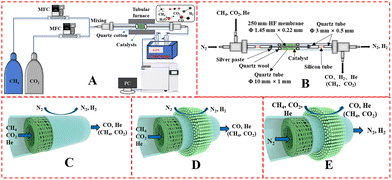 |
| | Fig. 3 Schematic illustration of (A) DRM catalytic reactor setup, (B) DRM membrane reactor; gas input method: fiber lumen feeding and shell side sweeping in (C) M1 mode, and (D) M2 mode, (E) shell side feeding and fiber lumen sweeping (M3 mode). | |
The DRM membrane reactor was assembled as shown in Fig. 3B. 0.50 g of 30 wt% Ni/BCYF–YDC catalyst was packed outside the HF with a packing length of 15 mm. There were two feeding configurations: fiber lumen feeding and shell side feeding, as shown in Fig. 3D and E.
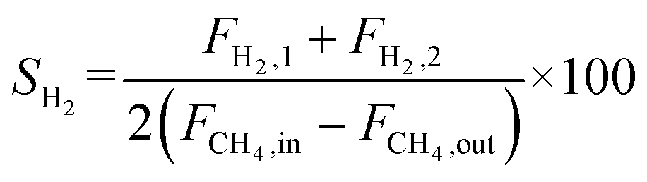
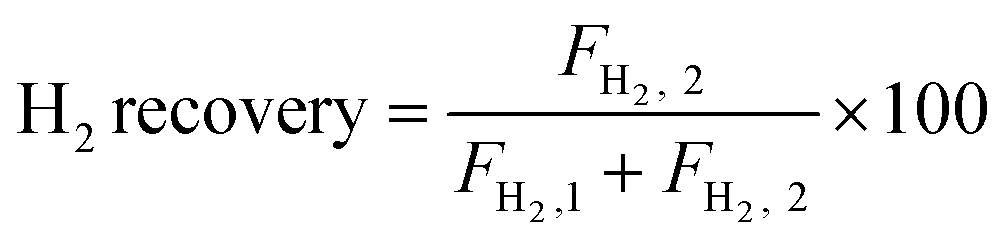
The autocatalytic effect of the membrane was investigated without the catalyst packing under fiber lumen feeding, as shown in Fig. 3C. The reaction and separation performance of the membrane reactor was evaluated by the CO2 and CH4 conversions, CO and H2 selectivities, and H2 recovery calculated using eqn (8), (10), (12), (15), and (16), respectively.
| | 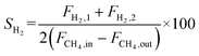 | (15) |
| |  | (16) |
X and
S were the conversion and selectivity, respectively, and
F was the gas flow rate (mL min
−1). The subscripts “in”, “1”, and “2” indicated the feed gas, the DRM reaction side, and the permeate side, respectively.
3. Results and discussion
3.1. Structure, thermal expansion and micromorphology of powder and HF membranes
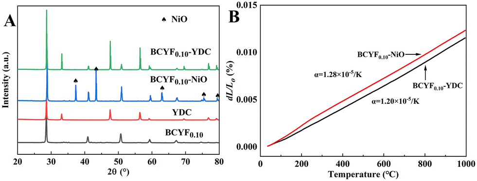
Fig. 4A shows the powder XRD patterns of BCYF0.10–YDC and BCYF0.10–NiO monolayer HF membranes and membrane material powders. No secondary phases were observed in the diffraction peaks, indicating that the membrane materials were structurally stable and chemically compatible. Correspondingly, no chemical reaction or thermal decomposition of the materials occurred during the high temperature sintering process. The high temperature conditions induced the fusion and growth between the grains to achieve greater crystallinity. The thermal expansion properties of the inner and outer membrane materials, i.e., BCYF0.10–NiO and BCYF0.10–YDC, sintered at 1600 °C were tested, the results of which are shown in Fig. 4B. The thermal expansion coefficients of the BCYF0.10–NiO inner layer and the BCYF0.10–YDC outer layer were 1.28 × 10⁻⁵ K−1 and 1.20 × 10⁻⁵ K−1, respectively, indicating that the two materials had good thermal expansion compatibility, thereby having less chance of cracking or peeling between the dual-layer membrane interfaces from temperature changes.
 |
| | Fig. 4 (A) Powder XRD pattern and (B) thermal expansion curves of BCYF0.10–YDC and BCYF0.10–NiO monolayer HF membranes and membrane material powders. | |
Fig. 5 shows the microscopic morphology of the 1600 °C-sintered BCYF0.10–YDC/BCYF0.10–NiO dual-layer HF membrane before and after reduction. The inner layer of the dual-layer HF membrane had finger-like and sponge-like pore structures. The inner and outer surfaces were gastight, and there was no obvious interface between the two layers, as shown in Fig. 5A2–A4. By reducing NiO in the inner layer of the HF membrane with H2, the BCYF0.10–Ni porous catalytic inner layer with small pores was obtained as displayed in Fig. 5B3. Nevertheless, the outer surface remained dense (Fig. 5B4), proving that BCYF0.10 and YDC were resistant to the high temperature H2 reduction. A comparison of the SEM images of the HF membranes before and after reduction revealed that the two layers were tightly bonded with no obvious interface or cracking. This was attributed to the sintering compatibility of the two layers (as shown in Fig. 4B), and the effective regulation of the casting solution and co-spinning-co-sintering parameters.
 |
| | Fig. 5 Microscopic morphology of BCYF0.10–YDC/BCYF0.10–NiO dual-layer HF membranes sintered at 1600 °C: (A) before reduction, (B) after reduction; (1) cross section, (2) membrane wall, (3) inner surface, (4) outer surface. | |
3.2. H2 permeation of BCYF0.10–YDC/BCYF0.10–Ni HF membranes
The H2 permeation performance of BCYF0.10–YDC/BCYF0.10–Ni dual-layer HF membranes was investigated before studying the catalytic performance. As shown in Fig. 6A, the H2 permeation flux increased with the H2 partial pressure at the feed side of the membrane. An increase in the H2 partial pressure difference induced the accelerated transport of protons and electrons, which led to an improvement in the H2 permeation flux. A H2 permeation flux of 0.21 mL min−1 cm−2 could be obtained at 900 °C with a small transmembrane pressure difference of 9.78 kPa.
 |
| | Fig. 6 H2 permeation performance of BCYF0.10–YDC/BCYF0.10–Ni double layer HF membranes at: (A) different H2 partial pressure difference (feed gas was 100 mL min−1 of H2/He mixture and sweep gas was 100 mL min−1 of N2); (B) different sweep gas flow rate (feed gas was 100 mL min−1 of 50 vol% H2/He mixture); (C) different humid atmospheres (feed gas was 100 mL min−1 of room-temperature steam saturated 50 vol% H2/He mixture and sweep gas was 100 mL min−1 of N2). | |
A greater pressure difference across the membrane can also be achieved by decreasing the H2 partial pressure at the permeate side. We have tested the H2 permeation flux of BCYF0.10–YDC/BCYF0.10–Ni dual-layer HF membrane at different sweep gas flow rates, with the results as shown in Fig. 6B. The increase in the sweep gas flow rate accelerated the H2 desorption rate at the permeate side, and increased the H2 permeation driving force. The results in Fig. 6A and B revealed that the H2 permeation flux increased with temperature. An increase in the temperature increased the membrane bulk diffusion rate and surface exchange rate, which in turn accelerated the H2 permeation flux.
The proton transport performance of the membrane can be improved in a humid atmosphere. The H2 permeation performance of BCYF0.10–YDC/BCYF0.10–Ni dual-layer HF membranes was experimentally evaluated in the presence of 3 vol% H2O in the feed or permeate side, and the results are shown in Fig. 6C. The introduction of steam at the feed side or permeate side could significantly improve the H2 permeation flux. When the feed side was humidified, it is known by eqn (17) and (18) that additional  would be generated in the wet atmosphere and accelerated the surface exchange reaction, thus, the H2 permeation flux would be increased. However, the introduction of steam would reduce the partial pressure of H2 at the feed side and decrease the transmembrane pressure difference of H2, thus reducing the H2 permeation driving force across the membrane. When the permeate side was humidified, hydration on the membrane surface and the transport rate of protons within the membrane could be accelerated, and the possible reaction is listed as eqn (19). The H2 permeation flux of the membrane was 1.30 mL min−1 cm−2 at 900 °C when the permeate side was humidified, which was 2.4 times than that under dry feed and sweep conditions.
| |  | (17) |
| | | H2 + H2O → H3O+ + H+ + 2e | (18) |
| | | 2H+ + 2H2O + 2e → 2H3O+ + 2e → H2 + 2H2O | (19) |
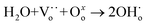
Currently, H2 is mainly derived from hydrocarbon reforming, which is often present together with CO2. Therefore, the H2 permeation performance of BCYF0.10–YDC/BCYF0.10–Ni dual-layer HF membranes under different concentrations of CO2/N2 sweep conditions was tested between 700 to 900 °C, and the results are shown in Fig. 7. The H2 permeation flux reached 2.21 mL min−1 cm−2 at 900 °C with 7.6 vol% CO2/N2 sweeping, which was 4.1 times than that under N2 sweeping. The main reason was that the permeated H2 underwent reverse water gas shift (RWGS) reaction, which increased the H2 partial pressure difference and the H2 permeation driving force across the membrane (Fig. 7C shows the H2 permeation process of the membrane under CO2 sweeping condition). The steam produced by the reaction additionally promoted the H2 permeation. The RWGS reaction is a heat-absorbing reaction (eqn (20)) whereby the reaction rate increased with an increase in temperature, and H2 consumption accelerated the H2 permeation flux. At 900 °C, the CO2 concentration increased from 7.6 to 20 vol%, and the corresponding H2 permeation flux decreased from 2.21 to 1.21 mL min−1 cm−2. One of the reasons for this was that the adsorption of CO2 on the membrane surface reduced the rate of H2 surface exchange reaction. In addition, the decrease in the H2 permeation rate might also be due to the formation of small amounts of carbonate that reduced the proton–electron migration properties. As shown in Fig. 7B, the CO yield of 9.53% at 900 °C was lower than the CO2 conversion rate of 16.13% at CO2 sweeping concentration of 20 vol%, which indicated the possible formation of carbonate at high CO2 concentration.
| | | CO2 + H2 → CO + H2O ΔH0298 = +41 kJ mol−1 | (20) |
 |
| | Fig. 7 (A) H2 permeation flux, (B) CO2 conversion and CO yield as a function of temperature for BCYF0.10–YDC/BCYF0.10–Ni dual-layer HF membranes under different concentrations of CO2 sweeping (feed gas was 100 mL min−1 of 50 vol% H2/He mixture and sweep gas was 100 mL min−1 of N2 with different concentrations of CO2); (C) schematic illustration of H2 permeation through dual-layer HF membranes under CO2 sweeping conditions. | |
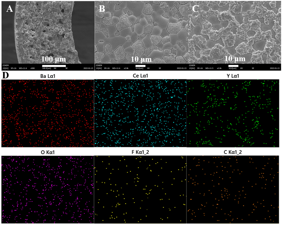
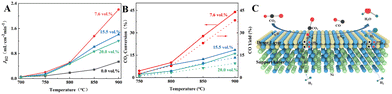
The microscopic morphology of the BCYF0.10–YDC/BCYF0.10–Ni dual-layer HF membrane after H2 permeation with CO2 sweeping is shown in Fig. 8. There was no significant change in the morphology of the inner surface of the membrane (Fig. 8B) as compared to that after H2 reduction (Fig. 5B3). The SEM image of the outer surface of the membrane (Fig. 8C) shows that the surface morphology of the membrane was no longer flat when the CO2-containing gas mixture was used as the sweep gas. The two phases could be easily distinguished based on the particle morphology; the rough and raised particles should be the BCYF0.10 phase, while the particles that remained smooth should be YDC phase. However, the dense structure of the membrane surface was still maintained without any large or micro cracks, which should be attributed to the presence of YDC phase limiting the reaction of BCYF0.10 phase and the volume expansion due to the formation of carbonate. The distribution of carbon and fluorine on the outer surface of the membrane in Fig. 8D were almost identical. The elemental distribution of Ba overlapped the raised part, which indicated that only the BCYF0.10 phase reacted with CO2, and this was the reason why the dual-phase membrane was more stable than the single-phase membrane.
 |
| | Fig. 8 Microscopic morphology of BCYF0.10–YDC/BCYF0.10–Ni dual-layer HF membrane after H2 permeation with CO2 sweeping: (A) membrane wall, (B) inner surface, (C) outer surface. And (D) corresponding EDS mapping of the outer surface in (C). | |
Nevertheless, a low CO2 conversion rate of 16.13% and CO yield of only 9.53% at a CO2 concentration of 20 vol% was achieved using the coupled membrane reactor for H2 separation and RWGS reaction. To further improve the membrane reactor performance and applicability, there is a need to develop suitable catalysts and H2 permeable membrane materials with CO2 resistance.
3.3. DRM and H2 separation performance of HF membrane reactors
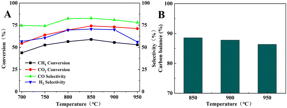
Fig. 9 shows the catalytic performance of the BCYF0.10–Ni powders in the DRM reaction. The CH4 and CO2 conversions increased from 43.8% and 54.5% to 58.9% and 74.1%, respectively; while the CO and H2 selectivity increased from 74.6% and 56.6% to 82.8% and 70.6%, respectively, when the temperature was increased from 700 °C to 850 °C. Since the DRM reaction is an endothermic reaction, the catalytic performance of BCYF0.10–Ni increased with temperature, and the CO2 conversion was higher than CH4 conversion because of the presence of the RWGS reaction. However, the catalytic performance of the membrane material started to decrease from 850 to 950 °C, and the conversion of CH4 and CO2 decreased from 58.9% and 74.1% to 52.9% and 71.1%, respectively, and the selectivity of CO and H2 decreased from 82.8% and 70.6% to 78.0% and 56.1%, respectively. As shown in Fig. 9B, the carbon balance was 86.4–88.6% from 850 to 950 °C, indicating that the active center of the catalyst was covered by carbon accumulation that in turn decreased the catalytic performance.
 |
| | Fig. 9 (A) DRM catalytic performance of BCYF0.10–Ni powder, (B) carbon equilibrium (feed gas was 50 mL min−1 CH4 and 50 mL min−1 CO2). | |
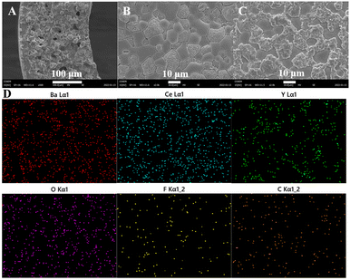
In view of the catalytic performance of BCYF0.10–Ni as the inner membrane material and the strong anti-coking effect of YDC,42 YDC phase (BCYF0.10:YDC = 1:2.5) was added to the inner membrane material and Ni/BCYF0.10–YDC catalysts with different Ni contents were investigated, the results of which are shown in Fig. 10. When the temperature was increased from 700 to 950 °C, the CH4 conversion increased from 21.9% to 74.5%, while the CO2 conversion increased from 34.8% to 87.1% for the 30 wt% Ni/BCYF0.10–YDC catalyst. The addition of the YDC phase significantly improved the coking resistance of the catalyst compared to the inner membrane material. In the reducing atmosphere, oxygen vacancies were generated in YDC due to the conversion between Ce4+ and Ce3+, which increased the oxygen ion mobility and improved the coking resistance and maintained the catalytic activity.5,46
 |
| | Fig. 10 DRM catalytic performance of Ni/BCYF0.10–YDC catalysts with different Ni contents: (A) CH4 and (B) CO2 conversion, (C) H2 and (D) CO selectivity, (E) carbon balance, and (F) H2/CO molar ratio (feed gas was 50 mL min−1 CH4 and 50 mL min−1 CO2). | |
At 950 °C, when the Ni content was 0 wt%, the catalysts showed only 12.7% and 24.2% of CH4 and CO2 conversions, and 82.0% and 19.3% of CO and H2 selectivities, respectively. When the Ni content was increased to 30 wt%, the catalysts showed the highest catalytic performance among other Ni-containing catalysts with CH4 and CO2 conversions of 74.5% and 87.1%, and CO and H2 selectivities of 89.5% and 92.3%, respectively. However, the catalytic performance did not continue to improve when the Ni content increased to 40 wt%, instead, CH4 and CO2 conversions decreased to 69.5% and 84.2%, and CO and H2 selectivities decreased to 87.4% and 85.2%, respectively. When the Ni content in the catalyst was increased beyond a certain level, the catalytic performance decreased with the increase in Ni content. Excessive Ni content would lead to the easy agglomeration and sintering of Ni metal in the catalyst, which would cause severe carbon accumulation and thereby lead to a decrease in the catalytic activity. As shown in Fig. 10E, the carbon was obviously out of balance, with only 90.3% at 950 °C for 40 wt% Ni catalyst. Based on the results in Fig. 10C, D, and F, the CO selectivity was always greater than H2 selectivity under the same conditions, and H2/CO molar ratio was always less than 1. This was due to the RWGS side reaction, whereby CO2 consumed part of H2 to produce CO and H2O, resulting in higher CO selectivity and lower H2 selectivity. Additionally, the trend in Fig. 10A and B indicate that the CO2 conversion was always greater than the CH4 conversion under the same conditions. Since the 30 wt% Ni catalyst exhibited the highest catalytic activity and relatively high H2/CO molarity, the 30 wt% Ni catalyst was selected for the packed membrane reactor.
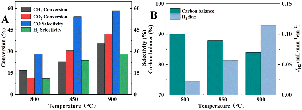
A 12.5/12.5/75 vol% CH4/CO2/He mixture with a flow rate of 80 mL min−1 was introduced into the fiber lumen of dual-layer HF membrane without catalyst packing, and the results of the DRM reaction and H2 separation performance are shown in Fig. 11. From Fig. 11A, the CH4 and CO2 conversions could only reach 36.0% and 42.1% at 900 °C, which was significantly lower compared to that of the inner layer material as the catalyst at 700 °C. This was because the membrane was sintered at 1600 °C and a dense connecting structure was formed among the grains, resulting in a lower specific surface area as well as a larger nickel grain size as shown in Fig. 5B3. The selectivities of CO and H2 were 58.3% and 28.3%, respectively, as shown in Fig. 11A, which were also much lower than that of the inner membrane material at 700 °C. As the permeation flux of H2 was only 0.11 mL min−1 cm−2 (Fig. 11B), only 11.5% of H2 was separated from the reaction side. The large concentration of CO2 in the reaction system was unable to inhibit the RWGS reaction, and consequently the selectivity of H2 remained lower than that of CO. The carbon balance was less than 84.0%, which indicated a significant carbon accumulation.
 |
| | Fig. 11 (A) CH4 and CO2 conversions and CO and H2 selectivities; (B) carbon balance and H2 permeation flux of BCYF0.10–YDC/BCYF0.10–Ni dual-layer HF membranes (fiber lumen: 80 mL min−1 12.5/12.5/75 vol% CH4/CO2/He, shell side: 80 mL min−1 N2 sweeping). | |
After evaluating the DRM performance of the BCYF0.10–YDC/BCYF0.10–Ni dual-layer HF membrane, the DRM performance of the membrane reactor packed with Ni/BCYF0.10–YDC catalyst with 30 wt% Ni at 900 °C was tested. The feed gas was 80 mL min−1 of 12.5 vol% CH4, 12.5 vol% CO2 and 75 vol% He mixture, with 80 mL min−1 N2 as sweep gas. From the CH4 and CO2 conversions shown in Table 3, the conversion of shell side feeding, i.e., CH4 and CO2 gas fed through the catalyst side (M3) produced the largest CH4 and CO2 conversions of 71.3% and 80.7%, respectively. Li et al.49 reported a tubular hydrogen-permeable ceramic membrane reactor consisting of a 33 μm-thick dense SrCe0.7Zr0.2Eu0.1O3−δ separation layer and a porous Ni–SrCe0.8Zr0.2O3−δ layer as support and catalyst for DRM. The simultaneous removal of H2 allowed the reactor system to surpass the DRM thermodynamic equilibrium, of which the SrCe0.7Zr0.2Eu0.1O3−δ membrane reactor showed a 10% increase in CO2 conversion at 900 °C with a 1:1 CH4 and CO2 feed. Accordingly, the H2 yield was increased by 15% under the above conditions. However, stability tests and carbon balance were not reported in their work, and carbon accumulation on the catalyst might be aggravated by the simultaneous removal of hydrogen from the reaction system. Although this problem could be alleviated by increasing the reaction temperature (above 800 °C), attempts should also be made to reduce the reaction temperature of DRM to save energy and capital costs. Therefore, a highly carbon-resistant catalyst was required for the DRM in H2 permeation ceramic membrane reactor. In addition, the membrane material should be stable in CO2 atmosphere at high temperatures.
Table 3 Performance comparison of BCYF0.10–YDC/BCYF0.10–Ni dual-layer HF membrane reactors at 900 °C (M1–M3 were fed and swept according to Fig. 3C–E, 80 mL min−1 12.5/12.5/75 vol% CH4/CO2/He feeding, 80 mL min−1 N2 sweeping)
|
|
X
CH4 (%) |
X
CO2 (%) |
S
CO (%) |
S
H2 (%) |
J
H2 (mL min−1 cm−2) |
H2 recovery (%) |
| M1 |
36.0 |
42.1 |
58.3 |
28.3 |
0.11 |
11.5 |
| M2 |
39.0 |
50.5 |
73.2 |
44.2 |
0.14 |
8.1 |
| M3 |
71.3 |
80.7 |
90.7 |
73.9 |
0.17 |
4.3 |
Since the catalyst tested in M3 mode did not undergo high temperature sintering at 1600 °C, the specific surface area was larger than that of the membrane material in the inner layer of the membrane. Consequently, the catalytic performance was better than those of M1 (BCYF0.10–YDC/BCYF0.10–Ni dual-layer HF membrane, as shown in Fig. 11A) and M2 modes. In addition, the conversions of CH4 and CO2 were comparable to those of the fixed-bed reactor with the same catalyst composition at 950 °C. The selectivities of CO and H2 were 90.7% and 73.9%, respectively, and the H2 selectivity of the membrane reactor was not improved compared to that of the fixed-bed reactor with 30 wt% Ni catalyst. The H2 partial pressure at the reaction side was low (only 9 vol%), and the catalyst packing increased the gas diffusion resistance, resulting in a low H2 permeation flux of the membrane (0.17 mL min−1 cm−2), and only 4.3% of H2 was separated from the reaction system, thus the promotion of H2 selectivity was not evident.
The comparison of the reaction results with the equilibrium composition may give valuable information to evaluate the effect of H2 separation by the membrane reactor. Hence, the equilibrium conversion (CH4 and CO2) and composition (H2, CO, CO2, H2O, CH4) as a function of temperature between 0 and 1000 °C were calculated with the results shown in Fig. S1.† As displayed, the equilibrium conversion of CH4 and CO2 at 900 °C should be 98.2% and 99.2%, respectively. However, the actual conversion of CH4 and CO2 at 900 °C was 57.7% and 75.3%, respectively. The difference between the equilibrium and actual conversion might be attributed to the poor catalytic performance of the catalyst prepared, which should be promoted in the future work. However, after assembling into membrane reactor with HF membrane, both of the conversion of CH4 and CO2 at 900 °C was promoted and reached 71.3% and 80.7%, respectively. The H2 separation by the HF membrane should be responsible to this promotion in the conversion of CH4 and CO2, while the catalytic performance of HF membrane itself was very limited according to the results shown in Fig. 11, i.e., the conversion of CH4 and CO2 at 900 °C was merely 36.0% and 42.1%, respectively.
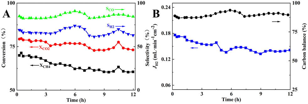
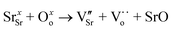
Finally, the short-term stability of the membrane reactor in M3 mode with the best reaction and separation performance was tested at 900 °C. As can be seen in Fig. 12, during the 12 h of operation, the CH4 and CO2 conversions decreased from 71.3% and 79.6% to 60.5% and 73.1%, respectively, and the carbon balance fluctuated around 89.4%, indicating a significant carbon accumulation, which was higher than that of the fixed-bed reactor assembled with the same catalyst composition. In the SEM image of the spent catalyst shown in Fig. S2,† filamentary and coated carbon could be observed, and the EDS mapping result showed that the carbon distribution was uniform. In addition, the blockage problem in the reactor did not occur after the stability test, and the pressure drop before and after the stability test was 11 and 13 Pa, respectively. H2 separation, which promoted carbon production from CH4 cracking reaction at high temperature (eqn (21)), led to carbon accumulation on the Ni metal surface, reduction of active centers, and lower catalytic performance. As a result of the RWGS reaction (eqn (20)), CO2 consumed part of H2 to produce CO and H2O, so the CO2 conversion and CO selectivity would be higher than that of CH4 conversion and H2 selectivity. The fluctuation of CO and H2 selectivities, i.e., the CO and H2 selectivities increased from 84.3% and 65.9% to 90.7% and 73.9%, respectively. This may be attributed to the increase in the CH4 cracking rate and higher production of H2 along with an increase in the RWGS reaction. The produced H2O underwent steam reforming with CH4 or reacted with carbon accumulation to produce more CO and H2, which suppressed the carbon accumulation, as displayed in eqn (20)–(23). For comparison, short-term stability test of 30 wt% Ni/BCYF0.10–YDC catalysts at 900 °C for 12 h was conducted with the results shown in Fig. S3.† During the 12 hour-test, the conversion of CH4 and CO2 increased from 47.8% and 72.4% to 74.9% and 88.9%, respectively, while the selectivity of CO fluctuated around 89% and the selectivity of H2 increased slowly from 70% to 86% (Fig. S3†). Upon comparing the results of membrane reactor and catalyst (Compare Fig. 3 to S3†), it becomes clear that the conversion of CH4 and CO2 in membrane reactor case was higher in the beginning relative to catalyst case. The selectivity of CO and H2 was also higher in membrane reactor case, although only slightly. This indicated that the introduction of hydrogen separation membrane could enhance the removal of hydrogen, one of the reaction products of DRM, which was beneficial to convert the reactants to the target products steadily and improve the catalytic performance of the reactor to a certain extent.
| | | CH4 → C + 2H2 ΔH0298 = +75 kJ mol−1 | (21) |
| | | C + H2O → CO + H2 ΔH0298 = +131 kJ mol−1 | (22) |
| | | CH4 + H2O → CO + 3H2 ΔH0298 = +206 kJ mol−1 | (23) |
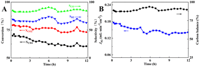 |
| | Fig. 12 Short-term stability of membrane reactor composed of 30 wt% Ni/BCYF0.10–YDC catalyst and BCYF0.10–YDC/BCYF0.10–Ni dual-layer HF membrane in M3 mode at 900 °C: (A) CH4, CO2 conversions and CO, H2 selectivities; (B) H2 permeation flux and carbon balance (shell side: 80 mL min−1 12.5/12.5/75 vol% CH4/CO2/He, fiber lumen: 80 mL min−1 N2 sweep). | |
Compared with the M1 and M2 modes, the good anti-coking properties of the YDC phase in the catalyst of the membrane reactor in the M3 mode allowed the membrane to retain its gas-tightness after 12 h of operation (the He concentration detected at the permeate side was kept at 0.04–0.05 vol%). This prevented any cracking of the membrane due to the increase in the fiber lumen pressure caused by the serious carbon accumulation in the M1 and M2 modes. However, since CO2 was the only source of oxygen in the system and had weak reactivity, the membrane reactor was in anoxic condition, and the in situ separation of H2 increased the degree of CH4 cleavage. Although the H2 separation efficiency was only 4.3%, the present work provided the feasibility of DRM and online separation of H2. Therefore, the membrane materials, membrane structures, and operating conditions of the coupled membrane reactor for DRM and H2 separation still need to be studied in depth and systematically. For instance, further work can be performed on the development of new materials to improve the H2 permeation performance and stability, the optimization of the composition and structure of catalysts to improve the anti-carbon accumulation and activating CO2 performance, the introduction of oxygen sources such as steam in the reaction system that do not affect the reaction efficiency, and the design of oxygen separation-DRM–H2 separation coupled membrane reactor.
4. Conclusions
In this work, BCYF0.10–YDC/BCYF0.10–Ni proton-electron mixed conducting dual-layer asymmetric HF H2-permeable ceramic membrane was fabricated by co-spinning-co-sintering technique, and the catalysts with different Ni contents were prepared by mechanical mixing method. DRM membrane reactor was constructed by packing the catalysts outside the BCYF0.10–YDC/BCYF0.10–Ni dual-layer HF membranes. The DRM reaction and H2 separation were carried out simultaneously, and the main conclusions are listed as follows:
(1) After H2 reduction, the H2 permeation rate of BCYF0.10–YDC/BCYF0.10–Ni dual-layer HF membrane increased with an increase in the temperature, the sweep gas flow rate, or the feed gas H2 partial pressure. The H2 permeation performance was promoted by the cracking of steam and the hydration of steam with the membrane. The presence of CO2 increased the H2 permeation by the RWGS reaction with H2. At 900 °C, the H2 permeation flux was increased to 1.30 mL min−1 cm−2 and 2.21 mL min−1 cm−2 when the sweep gas was 3 vol% H2O/N2 or 7.6 vol% CO2/N2, respectively, which was 2.4 and 4.1 times that of the H2 permeation under the pure N2 sweeping.
(2) The addition of YDC phase significantly improved the anti-coking performance of the catalyst, and the Ni content of the catalyst had a significant effect on the DRM performance of Ni/BCYF0.10–YDC catalyst. At 950 °C, the conversions of CH4 and CO2 were 74.5% and 87.1%, and the selectivities of CO and H2 were 89.5% and 92.3%, respectively, for the 30 wt% Ni catalyst; when the Ni content was 40 wt%, the catalytic performance of the catalyst decreased.
(3) At 900 °C, the membrane reactor with the catalyst packed in the shell side maintained good stability during 12 h of continuous operation, and the carbon balance was around 89.4%. The feasibility of constructing a DRM–H2 separation coupled membrane reactor for online H2 separation was demonstrated. However, the DRM–H2 separation coupled membrane reactor still needs to be studied systematically and thoroughly in terms of membrane material, membrane structure, catalyst, and operating conditions.
Author contributions
Jie Wang: data curation, validation, investigation, methodology. Baolei Shao: data curation, validation, investigation, writing – original draft. Claudia Li: writing, review & editing. Jian Song: supervision, funding acquisition, conceptualization, writing, review & editing. Bo Meng: supervision, project administration, conceptualization. Xiuxia Meng: project administration. Naitao Yang: project administration. Sibudjing Kawi: funding acquisition, project administration. Jaka Sunarso: supervision, project administration, writing, review & editing. Xiaoyao Tan: supervision, funding acquisition, project administration. Shaomin Liu: supervision, funding acquisition, project administration.
Conflicts of interest
There are no conflicts to declare.
Acknowledgements
The authors gratefully acknowledge the research fundings provided by the National Natural Science Foundation of China (NSFC 22179073, 21805206, 22178271, and 22178015), Youth Innovation Team of Colleges and Universities in Shandong Province (2022KJ230), Major Project of Natural Science Foundation in Shandong Province (ZR2020KB002), and the Fundamental Research Funds for the Central Universities (buctrc202115). The authors also acknowledge the financial support from A*STAR LCER-FI Project (WBS: A-8000278-00-00) and FRC MOE T1 (WBS: A-0009184-00-00).
Notes and references
- S. Bhattar, M. A. Abedin, S. Kanitkar and J. J. Spivey, Catal. Today, 2021, 365, 2–23 CrossRef CAS.
- F. D. A. R. da Silva, R. C. R. dos Santos, R. S. Nunes and A. Valentini, Appl. Catal., A, 2021, 618, 118129 CrossRef CAS.
- Q. Zhu, H. Cheng, X. Zou, X. Lu, Q. Xu and Z. Zhou, Chin. J. Catal., 2015, 36, 915–924 CrossRef CAS.
- X. Gao, Z. Lin, T. Li, L. Huang, J. Zhang, S. Askari, N. Dewangan, A. Jangam and S. Kawi, Catalysts, 2021, 11, 455–476 CrossRef CAS.
- L. P. Teh, H. D. Setiabudi, S. N. Timmiati, M. A. A. Aziz, N. H. R. Annuar and N. N. Ruslan, Chem. Eng. Sci., 2021, 242, 116606 CrossRef CAS.
- F. S. Al-Mubaddel, R. Kumar, M. L. Sofiu, F. Frusteri, A. A. Ibrahim, V. K. Srivastava, S. O. Kasim, A. H. Fakeeha, A. E. Abasaeed, A. I. Osman and A. S. Al-Fatesh, Int. J. Hydrogen Energy, 2021, 46, 14225–14235 CrossRef CAS.
- N. A. K. Aramouni, J. Zeaiter, W. Kwapinski, J. J. Leahy and M. N. Ahmad, Fuel, 2021, 300, 120950 CrossRef CAS.
- S. D. Angeli, S. Gossler, S. Lichtenberg, G. Kass, A. K. Agrawal, M. Valerius, K. P. Kinzel and O. Deutschmann, Angew. Chem., Int. Ed., 2021, 60, 11852–11857 CrossRef CAS PubMed.
- J. Kim, S. Sengodan, S. Kim, O. Kwon, Y. Bu and G. Kim, Renewable Sustainable Energy Rev., 2019, 109, 606–618 CrossRef CAS.
- F. Gallucci, E. Fernandez, P. Corengia and M. van Sint Annaland, Chem. Eng. Sci., 2013, 92, 40–66 CrossRef CAS.
- H. Wang, X. Wang, B. Meng, X. Tan, K. S. Loh, J. Sunarso and S. Liu, J. Ind. Eng. Chem., 2018, 60, 297–306 CrossRef CAS.
- G. Bernardo, T. Araújo, T. da Silva Lopes, J. Sousa and A. Mendes, Int. J. Hydrogen Energy, 2020, 45, 7313–7338 CrossRef CAS.
- W. Deibert, M. E. Ivanova, S. Baumann, O. Guillon and W. A. Meulenberg, J. Membr. Sci., 2017, 543, 79–97 CrossRef CAS.
- S. S. Hashim, M. R. Somalu, K. S. Loh, S. Liu, W. Zhou and J. Sunarso, Int. J. Hydrogen Energy, 2018, 43, 15281–15305 CrossRef CAS.
- G. C. Mather, S. García-Martín, D. Benne, C. Ritter and U. Amador, J. Mater. Chem., 2011, 21, 5764–5773 RSC.
- H. Zhou, L. Dai, L. Jia, J. Zhu, Y. Li and L. Wang, Int. J. Hydrogen Energy, 2015, 40, 8980–8988 CrossRef CAS.
- F. Su, C. Xia and R. Peng, J. Eur. Ceram. Soc., 2015, 35, 3553–3558 CrossRef CAS.
- M. Yang, F. He, C. Zhou, F. Dong, G. Yang, W. Zhou and Z. Shao, J. Membr. Sci., 2021, 620, 118980 CrossRef CAS.
- L. Zhuang, J. Li, J. Xue, Z. Jiang and H. Wang, Ceram. Int., 2019, 45, 10120–10125 CrossRef CAS.
- X. Ma, C. Yang, H. Chen, Q. Lv, K. Sun and W. Li, Sep. Purif. Technol., 2020, 236, 116276 CrossRef CAS.
- Y. Itagaki, A. Hiraoka, H. Aono and H. Yahiro, J. Ceram. Soc. Jpn., 2017, 125, 338–342 CrossRef CAS.
- C. Yang, X. Ma, H. Chen, Q. Lv, K. Sun, J. Chen and S. Yun, J. Alloys Compd., 2018, 762, 409–414 CrossRef CAS.
- J. M. Polfus, W. Xing, M.-L. Fontaine, C. Denonville, P. P. Henriksen and R. Bredesen, J. Membr. Sci., 2015, 479, 39–45 CrossRef CAS.
- Y. Liu, L. Dai, W. Zhang, H. Zhou, Y. Li and L. Wang, Ceram. Int., 2016, 42, 6391–6398 CrossRef CAS.
- C. Mortalò, E. Rebollo, S. Escolástico, S. Deambrosis, K. Haas-Santo, M. Rancan, R. Dittmeyer, L. Armelao and M. Fabrizio, J. Membr. Sci., 2018, 564, 123–132 CrossRef.
- Z. Zhu, J. Hou, W. He and W. Liu, J. Alloys Compd., 2016, 660, 231–234 CrossRef CAS.
- K. Zhang, J. Sunarso, G. H. Pham, S. Wang and S. Liu, Ceram. Int., 2014, 40, 791–797 CrossRef CAS.
- H. Cheng, B. Meng, C. Li, X. Wang, X. Meng, J. Sunarso, X. Tan and S. Liu, Int. J. Hydrogen Energy, 2020, 45, 7423–7432 CrossRef CAS.
- E. Mercadelli, A. Gondolini, D. Montaleone, P. Pinasco, S. Escolástico, J. M. Serra and A. Sanson, Int. J. Hydrogen Energy, 2020, 45, 7468–7478 CrossRef CAS.
- B. Meng, H. Wang, H. Cheng, X. Wang, X. Meng, J. Sunarso, X. Tan and S. Liu, Sep. Purif. Technol., 2019, 213, 515–523 CrossRef CAS.
- X. Meng, Y. Shang, B. Meng, N. Yang, X. Tan, J. Sunarso and S. Liu, J. Eur. Ceram. Soc., 2016, 36, 4123–4129 CrossRef CAS.
- T. Wang, H. Wang, X. Meng, B. Meng, X. Tan, J. Sunarso and S. Liu, Int. J. Hydrogen Energy, 2017, 42, 12301–12309 CrossRef CAS.
- X. Tan, X. Tan, N. Yang, B. Meng, K. Zhang and S. Liu, Ceram. Int., 2014, 40, 3131–3138 CrossRef CAS.
- H. Liu, Y. Chen, Y. Wei and H. Wang, Int. J. Hydrogen Energy, 2017, 42, 4208–4215 CrossRef CAS.
- Y. Shang, L. Wei, X. Meng, B. Meng, N. Yang, J. Sunarso and S. Liu, J. Membr. Sci., 2018, 546, 82–89 CrossRef CAS.
- H. Cheng, X. Wang, X. Meng, B. Meng, J. Sunarso, X. Tan, L. Liu and S. Liu, J. Membr. Sci., 2020, 601, 117801 CrossRef CAS.
- Y. Wei, J. Xue, H. Wang and J. Caro, J. Membr. Sci., 2015, 488, 173–181 CrossRef CAS.
- Z. Wu, B. Wang and K. Li, J. Membr. Sci., 2010, 352, 63–70 CrossRef CAS.
- X. Bi, X. Meng, P. Liu, N. Yang, Z. Zhu, R. Ran and S. Liu, J. Membr. Sci., 2017, 522, 91–99 CrossRef CAS.
- M.-L. Fontaine, C. Denonville, Z. Li, W. Xing, J. M. Polfus, J. Kvello, J. S. Graff, P. I. Dahl, P. P. Henriksen and R. Bredesen, J. Eur. Ceram. Soc., 2018, 38, 1695–1701 CrossRef CAS.
- I. V. Yentekakis, P. Panagiotopoulou and G. Artemakis, Appl. Catal., B, 2021, 296, 120210 CrossRef CAS.
- R.-Y. Chein and W.-Y. Fung, Int. J. Hydrogen Energy, 2019, 44, 14303–14315 CrossRef CAS.
- K. Han, W. Yu, L. Xu, Z. Deng, H. Yu and F. Wang, Fuel, 2021, 291, 120182 CrossRef CAS.
- F. V. Maziviero, R. L. B. A. Medeiros, D. M. A. Melo, H. P. Macedo, Â. A. S. Oliveira and T. R. Araújo, Mater. Chem. Phys., 2021, 264, 124408 CrossRef CAS.
- C. M. Damaskinos, J. Zavašnik, P. Djinović and A. M. Efstathiou, Appl. Catal., B, 2021, 296, 120321 CrossRef CAS.
- S. Das, A. Jangam, S. Jayaprakash, S. Xi, K. Hidajat, K. Tomishige and S. Kawi, Appl. Catal., B, 2021, 290, 119998 CrossRef CAS.
- B. Meng, S. Wu, S. Zhang, C. Li, J. Song, N. Yang, J. Sunarso, X. Tan, M. Wang and S. Liu, Sep. Purif. Technol., 2022, 300, 121900 CrossRef CAS.
- J. Song, C. Li, S. Zhang, K. Wang, B. Meng, X. Tan, J. Sunarso and S. Liu, J. Ind. Eng. Chem., 2022, 107, 100–108 CrossRef CAS.
- J. Li, H. Yoon and E. D. Wachsman, Int. J. Hydrogen Energy, 2012, 37, 19125–19132 CrossRef CAS.
|
| This journal is © The Royal Society of Chemistry 2023 |
Click here to see how this site uses Cookies. View our privacy policy here. 
 a,
Baolei
Shao
a,
Claudia
Li
a,
Baolei
Shao
a,
Claudia
Li


 would be generated in the wet atmosphere and accelerated the surface exchange reaction, thus, the H2 permeation flux would be increased. However, the introduction of steam would reduce the partial pressure of H2 at the feed side and decrease the transmembrane pressure difference of H2, thus reducing the H2 permeation driving force across the membrane. When the permeate side was humidified, hydration on the membrane surface and the transport rate of protons within the membrane could be accelerated, and the possible reaction is listed as eqn (19). The H2 permeation flux of the membrane was 1.30 mL min−1 cm−2 at 900 °C when the permeate side was humidified, which was 2.4 times than that under dry feed and sweep conditions.