 Open Access Article
Flexible transparent film heaters using a ternary composite of silver nanowire, conducting polymer, and conductive oxide†
Juhyung Park a,
Dongjun Hana,
Seunghwan Choi
 b,
Yunkyung Kimb and
Jeonghun Kwak
 *a
*a
aSchool of Electrical and Computer Engineering, University of Seoul, Seoul 02504, South Korea. E-mail: jkwak82@uos.ac.kr
bDepartment of Electronics Engineering, Dong-A University, Busan 49315, South Korea
First published on 15th February 2019
Abstract
Scientific and technological advances in transparent conductive electrodes improve the heating performance of flexible transparent film heaters (TFHs), which can be utilized for various applications as defrosters and heaters. To achieve high performance as well as practical TFHs, several conditions, such as high optical transmittance, low electrical resistance, heating uniformity, and operational stability in various environmental conditions should be satisfied. However, due to the trade-offs between optical transmittance and electrical resistance, it is not easy to fulfill all the requirements concurrently. Here we report flexible TFHs using a ternary composite of silver nanowire (AgNW), conducting polymer (i.e., poly[3,4-ethylenedioxythiophene]:polystyrene sulfonate [PEDOT:PSS]), and a thin conductive oxide (i.e., indium tin oxide [ITO]) layer, exhibiting higher performance in terms of the maximum heating temperature (>110 °C), operational stability, mechanical flexibility, and optical transmittance (95% at 550 nm), compared to pristine AgNW-based TFHs. We also demonstrated the stable operation of the AgNW–PEDOT:PSS/ITO TFHs soaked in water, showing excellent environmental stability. To analyse the fundamental mechanisms for the improved performance of the AgNW–PEDOT:PSS/ITO TFHs, we investigated the progress of joule heating using a device simulator, and found that the improvement originated not only from reduced electrical resistance but also from enhanced heat dissipation with PEDOT:PSS and ITO. We anticipate that our analysis and results will be helpful for further development of practical flexible TFHs.
Introduction
Flexible transparent film heaters (TFHs), which generate heat by joule heating, are attracting increasing attention because they can be utilized for defrosters in mirrors, windows, and outdoor displays, and for heaters in wearable devices.1–6 Practically, indium tin oxide (ITO) is the most widely used for transparent heaters due to its outstanding transparency and electrical conductivity among various transparent conductive oxides (TCOs). However, the poor mechanical properties of the ITO prevent it from being utilized in flexible devices. It is well-known that repetitive mechanical movements induce cracks in the ITO, resulting in significant degradation of electrical conductivity.7,8 In addition, the limited supply of indium is one another reason why we should find a substitutional conductive material for flexible TFHs. Owing to multilateral efforts, to date, several materials have been introduced for high performance flexible TFHs. For instance, metal nanowires such as Ag nanowires (AgNWs) and Cu nanowires (CuNWs),9–12 carbon nanotubes (CNTs),13,14 graphene,15–17 conducting polymers,18 and their composites.19–29 Among them, AgNWs are considered as the most promising candidate for flexible TFHs because of their superb electrical conductivity, high optical transmittance (TR) in visible spectral ranges, and excellent mechanical stability, since Celle et al. demonstrated AgNW-based flexible TFHs in 2012.30 Moreover, large-area flexible TFHs can be mass-producible in various low-cost deposition processes, such as slot-die coating, spray-coating, and consecutive roll-to-roll (R2R) methods.31–33 In spite of those advantages, AgNW-based thin films suffer from inherent weakness of high junction resistance by the insulating ligands (e.g., polyvinylpyrrolidone) surrounding the AgNWs and poor interconnections between their random networks.34,35 These properties degrade both of the electrical and heating performance of TFHs, resulting in local hot spots, nonuniform heat distribution, and failure of the TFHs at a low heating temperature.36–38To overcome these problems, various techniques have been employed in AgNW-based TFHs. For example, electron beam assisted nano-soldering of AgNW junctions was reported in 2015 to enhance the interconnection between AgNWs and the heating performance.39 Flash-induced plasmonic welding was also introduced in 2017 to reduce the contact resistance between AgNWs.40 Another approach to improve the electrical and heating performance of flexible AgNW-based TFHs is to incorporate other conductive materials, such as CNTs,19–21 graphene,22–24 metal oxides,25–27 and conducting polymers.28,29 Most of the TFHs using AgNW composites exhibit reduced electrical resistance and resultant higher heater performance in terms of the maximum temperature and thermal uniformity compared to the devices with pristine AgNWs, mainly because of the improved interconnection between AgNW random networks. However, there are trade-offs between electrical properties and other properties in the AgNW composite films. For instance, optical transmittance may be decreased by incorporating CNTs or conducting polymers (e.g., polyaniline and poly[3,4-ethylenedioxythiophene]:polystyrene sulfonate [PEDOT:PSS]) which typically absorb visible light.19–21,28 When metal oxides, such as ITO, aluminium zinc oxide, and fluorine-doped tin oxide, are adopted, mechanical flexibility of the film becomes poor as mentioned above, although they possess decent electrical and optical properties. In case of graphene, the composites can have advantages in transparency, electrical and thermal conductivity. However, the fabrication process for graphene requires high temperature and complicated steps (e.g., thermal reduction of graphene oxides or chemical vapour deposition),22,23 which is not favourable with the fabrication process for low-cost, large-sized flexible TFHs.
Herein, we report highly power-efficient, easily processible, and highly flexible TFHs using a ternary composite of AgNW, PEDOT:PSS, and ITO. This film exhibited improved electrical conductivity and uniformity with high optical transmittance of 95% at 550 nm because of PEDOT:PSS and an additional thin ITO layer (10 nm). As a result, the flexible TFHs showed improved thermal resistance with the maximum temperature of over 110 °C and with homogeneous temperature distribution. The maximum temperature as well as mechanical flexibility were enhanced compared with the pristine AgNW and AgNW–PEDOT:PSS devices. To find out the reasons, we observed optical, electrical, and mechanical characteristics of the composite films systematically. We also investigated the progress of joule heating in the pristine and composite films using a device simulation tool. Here we newly found that the flexible TFHs using the AgNW–PEDOT:PSS/ITO can endure the higher temperature than the other devices because of not only reduced electrical resistance but also enhanced heat dissipation. Moreover, the TFHs exhibited stable operation in water, which is highly desired for use in various outdoor environmental conditions.
Results and discussion
Fig. 1(a)–(c) show the schematic images of the three AgNW composite films for flexible TFHs fabricated on poly(ethylene terephthalate) (PET) with the scanning electron microscopy (SEM) image, consisting of AgNW, AgNW–PEDOT:PSS, and AgNW–PEDOT:PSS/ITO. The PEDOT:PSS and ITO were adopted to enhance the electrical uniformity by filling the gaps between AgNWs with the minimum transparency loss, as reported previously.32 The average width of the AgNWs was ∼35 nm. In the AgNW–PEDOT:PSS film, there are few remarkable changes but the width of some AgNWs look slightly thinner, meaning that PEDOT:PSS properly infiltrated into empty space between AgNWs. When an ITO layer was added, the width of the AgNWs increased up to 50 nm because the ITO layer covered the AgNWs. Consequently, the empty space between AgNWs are considered to be filled with PEDOT:PSS and ITO. Fig. 1(d) shows the optical transmittance spectra of the films. Although TR was slightly decreased when the PEDOT:PSS and ITO was added, all the films exhibits high TR of above 95% at 550 nm, which are comparably high values among those of previously reported AgNW composite films.19–29 The sheet resistance (RS) values of the AgNW, AgNW–PEDOT:PSS, and AgNW–PEDOT:PSS/ITO films were 42.2 ± 1.5, 52.8 ± 1.4, and 41.4 ± 1.1 Ω sq−1, respectively, which are plotted in Fig. 1(e). Only the AgNW–PEDOT:PSS film showed slightly higher RS than the other films, due to the relatively higher electrical resistance of the pristine PEDOT:PSS. When a thin ITO layer was added, RS of the film became comparable to the pristine AgNW film.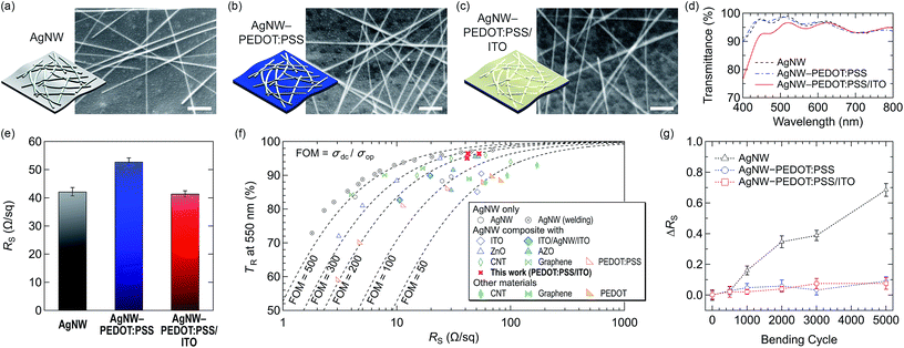 | ||
| Fig. 1 (a)–(c) Schematic illustration and SEM images of the AgNW, AgNW–PEDOT:PSS, and AgNW–PEDOT:PSS/ITO composite films, respectively. (d) Transmittance and (e) sheet resistance of the films. (f) The FOM values for the AgNW,10 AgNW (welding),11 AgNW composites (with ITO,42 ITO/AgNW/ITO,25 ZnO,26 AZO,27 CNT,33 graphene,24 and PEDOT:PSS28), and other materials without AgNWs (CNT,14 graphene,17 and modified PEDOT18) are compared with the values obtained from this work. (g) Relative sheet resistance change (ΔRS) of the films according to the number of bending cycles. | ||
For being a good transparent conductor, low RS and high TR should be achieved at the same time. However, as can be seen in the results above, it is hard to improve both electrical and optical properties simultaneously. Thus it is advantageous to obtain a high figure of merit (FOM) which is defined from the following TR–RS relationship,41
Another desirable factor for TFHs is mechanical flexibility. We tested mechanical flexibility and durability using a cyclic bending machine. The relative RS change (ΔRS) of the films according to the number of bending cycles is defined as
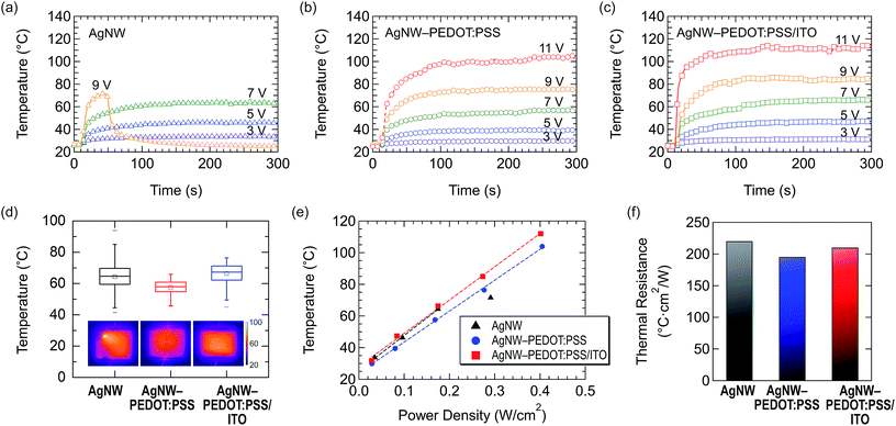
To characterize the performance of the AgNWs and their composite-based flexible TFHs, we recorded the temperature changes with an infrared (IR) camera for 300 s, while each voltage from 3 to 11 V was applied. Fig. 2(a)–(c) compare the temperature profiles of three flexible TFHs over time. All the films reached its steady-state temperature at around 70 s. The saturated temperature of the AgNW TFH was 33 °C at 3 V, and it was increased to 64 °C at 7 V. But the AgNW TFH exhibited a breakdown during the operation at the bias voltage of 9 V. It is likely that high junction resistance between the AgNWs made local hot spots, which destroyed the connection between the AgNWs.9,37 In contrast, the AgNW–PEDOT:PSS TFH endured higher voltages, generating the temperature of 105 °C at 11 V. It can be supposed that PEDOT:PSS effectively extended the electric conduction paths and reduced the junction resistance between AgNWs. Although the maximum heating temperature of the AgNW–PEDOT:PSS TFH was increased, the temperature at the same bias voltage is lower than that of the AgNW TFH, because of its higher RS. This demerit can be surmounted by adopting a thin ITO layer onto the AgNW–PEDOT:PSS film. As shown in Fig. 2(c), the AgNW–PEDOT:PSS/ITO TFH exhibits the saturation temperature of the ∼115 °C at 11 V bias, which is about 10 °C higher than that without an ITO layer at the same bias voltage. It is attributed to the reduced the resistance of the AgNW–PEDOT:PSS/ITO film, which is comparable to the value of the pristine AgNW film. Also, the ITO layer functions as a blanket which effectively reduce the thermal losses from the film to air.42
It is known that self-aggregation, high junction resistance, and poorly interconnected AgNW networks are major reasons for local hot spots which reduce the stability of TFHs. In other words, heating performance uniformity is a crucial factor for TFHs. Therefore, we analysed the heating uniformity at 7 V (in steady-state) using the areal temperature distribution of the films obtained from their IR photos. As plotted in Fig. 2(d) with the box-and-whisker plots, the AgNW demonstrates the mean temperature as high as ∼64.4 °C. However, the interquartile range (IQR) value (defined as IQR = first quartile − third quartile of data) is larger than the other devices. Moreover, the whiskers for the minimum and the maximum are drawn farthest from each other; that is, the highest local maximum temperature was as high as 93.9 °C while the lowest local minimum temperature was 41.4 °C. On the other hand, the AgNW–PEDOT:PSS film presents the most homogeneous temperature distribution with the smallest IQR value, which is attributed to PEDOT:PSS. However, the heating temperature was much lower than the other TFHs at the same voltage due to the high RS. The AgNW–PEDOT:PSS/ITO film exhibits moderate uniformity in temperature distribution, as compared with the other samples. But the box-plot shows that considerable data points of local temperatures are leaning to the higher temperature range than the median value. The IR images of the films at 7 V are shown in inset of Fig. 2(d).
We also compared the heating temperature at the same input power density, as shown in Fig. 2(e). The pristine AgNW and AgNW–PEDOT:PSS/ITO TFHs exhibit almost similar heating temperatures at the same power density until 0.17 W cm−2. But the AgNW sample shows evident degradation at higher input power density. The AgNW–PEDOT:PSS TFH can endure much higher input power density than the AgNW sample, but the heating performance is lower than the others. This result also shows the advantage of the ternary composite film for flexible TFHs over the other samples. We also calculated the thermal resistance of unit area (or the thermal insurance) of the AgNW and AgNW composite films by fitting the heating temperature–input power density data in Fig. 2(e), as compared in Fig. 2(f). The thermal resistance of the AgNW–PEDOT:PSS/ITO TFH is 210.3 °C cm2 W−1, which is approximately 7.6% higher than that of the AgNW–PEDOT:PSS TFH (195.5 °C cm2 W−1). The results demonstrate that the introduction of a thin ITO layer improves the power efficiency of the TFHs. It is not surprising that the thermal resistance of the pristine AgNW film, 220.3 °C cm2 W−1, is the highest value when considering its sheet resistance. But as mentioned above, the sample did not endure high input power density, debasing the usefulness as a TFH. Therefore, based on the heating performance results, we consider that the AgNW–PEDOT:PSS/ITO film can be an excellent candidate for practical use in TFHs.
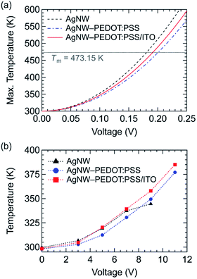
For deeper understanding of heating performance of the AgNW-based TFHs, for instance the maximum temperature and heat distribution, we conducted a joule heating simulation using a device simulator, Lumerical DEVICE. To figure out the phenomena especially at AgNW junctions, we let two AgNWs cross each other, and applied voltages to make electric current flow from one AgNW to the other AgNW through the junction, as schematically described in Fig. S1 in ESI.† We added a PEDOT:PSS layer (17.5 nm) and an additional ITO layer (10 nm) onto the AgNWs for the simulation of AgNW–PEDOT:PSS and AgNW–PEDOT:PSS/ITO, respectively. The current flow by the applied voltage (from 0 V to 0.3 V) through the AgNWs leads to an ohmic power loss in the wires which is dissipated as heat. Fig. 3(a) shows the simulated maximum temperatures within the films by joule heating between two AgNWs. As the bias voltage was increased, the maximum temperature of the AgNWs increased accordingly. A horizontal line at 473.15 K corresponds to the melting point (Tm) of AgNWs,43 which could be the starting point of local failure within the THFs. The simulation results show that the AgNWs reach Tm at the lowest voltage of 0.181 V, whereas the AgNW–PEDOT:PSS film reach Tm at about 11% higher voltage of 0.200 V. In case of the AgNW–PEDOT:PSS/ITO, Tm was achieved at 0.191 V. We found that the results well agree with the empirical data in Fig. 3(b) as well as the sheet resistance of three samples in Fig. 1(e). A notable difference in the empirical data compared to the simulation is that the mean temperature of the AgNW TFH is higher than the others at low voltages but it decreases as the voltage increases (at about >4 V). Finally, the temperature is lowest among three THFs at 9 V, which is attributed to local junction failure within the AgNW networks, as confirmed above.
To understand the simulation results more in detail, we explored the cross-sectional heat distributions at the centre of the simulation configuration (see Fig. S1 in ESI† for the detailed position), as depicted in Fig. 4(a)–(c). Following Fig. 4(d)–(f) present the simulated heat distributions when the maximum temperatures reach 473.15 K. In case of the pristine AgNWs (Fig. 4(d)), Tm is observed at the cross point of two AgNWs due to the high contact resistance. At this moment, however, the temperatures of the other parts of the substrates as well as the AgNWs was much lower (i.e., 340–370 K) than the cross point. Thus, we can only expect low heating temperature in the TFH with the pristine AgNWs. On the contrary, we can observe the widespread heat distribution around the AgNWs in the PEDOT:PSS-containing AgNW films (Fig. 4(e) and (f)) when the maximum temperature is Tm. It is noteworthy that the cross point of two AgNWs reach Tm most quickly as the AgNW film. Higher AgNW temperatures originate from the improved AgNW interconnection and more intimate contacts between AgNWs, caused by PEDOT:PSS and ITO. In addition, significant temperatures difference in the substrate and the AgNW periphery regions including the substrate region composite films can be achievable by enhanced joule heat dissipation by fully covering the surface of the PET substrate. In case of AgNW, it can have extremely small contact area due to its shape. Higher performance in the AgNW–PEDOT:PSS/ITO film than in the AgNW–PEDOT:PSS film may be attributed to the higher electrical and thermal conductivity of ITO compared to PEDOT:PSS. Based on the device simulation, to summarize, we confirm that the ternary composite film can demonstrate the highest heating temperature with uniformity.
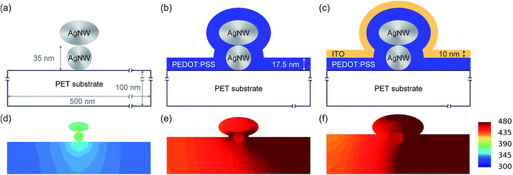 | ||
| Fig. 4 (a)–(c) Schematic illustration and specification of the cross-section of the AgNW, AgNW–PEDOT:PSS, and AgNW–PEDOT:PSS/ITO films in the device simulation, and (d)–(f) the resulting temperature distribution when the maximum temperature reaches Tm. Note that the detailed position of the cross-section is depicted in Fig. S1 in ESI.† | ||
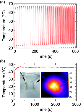
Finally, to verify the operation and environmental stability of the AgNW–PEDOT:PSS/ITO TFHs, we conducted the cyclic heating and cooling test by applying (7 V, 10 s) and releasing the voltage (10 s) for 30 cycles. As shown in Fig. 5(a), the flexible TFH heated up to over 65 °C and cooled down to near the room temperature, showing good response time, operational stability, and repeatability. We also tested the environmental stability by operating the TFH soaked in deionized water in a plastic Petri dish, as shown in Fig. 5(b). The inset photograph shows the measurement setup while the IR image presents heat radiation at 7 V in water. Due to the high specific heat of water, the maximum temperature is held at ∼47 °C. Nevertheless, stable operation in water maintained for more than 3000 s, which must be meaningful for practical use under a variety of outdoor conditions (also see Fig. S2 and a movie clip in ESI†).
Conclusions
This work presents the development of the high performance flexible TFHs with excellent flexibility and stability by using a ternary composite of AgNW–PEDOT:PSS/ITO. This hybrid film based TFHs exhibit simultaneous improvement in electrical, mechanical, and heating properties with little loss of optical transmittance, compared to the pristine AgNW TFHs. In particular, highly uniform and environmentally stable TFHs are developed by the introduction of a thin ITO layer, enabling to demonstrate the operation of the TFHs even in water. Also, the fundamental device simulation on the AgNWs and their composite films revealed the mechanisms of the enhancement and failure by showing a few physical phenomena, such as local heating and heat dissipation in the films. We believe that the concepts, results, analysis must be sufficiently helpful for further development of practical flexible TFHs.Experimental section
Three kinds of the AgNW and AgNW composite films were supplied by Inktec, which were prepared according to the previously reported procedure.32 The AgNW ink (0.1 wt%) was purchased from Nanopyxis. PEDOT:PSS (Clevios PH 1000, 1![[thin space (1/6-em)]](https://www.rsc.org/images/entities/char_2009.gif) :
:![[thin space (1/6-em)]](https://www.rsc.org/images/entities/char_2009.gif) 2.5 by weight) was purchased Heraeus Precious Metals. To form the films with a slot-die coater, the AgNW and AgNW–PEDOT:PSS (solid weight ratio of 2
2.5 by weight) was purchased Heraeus Precious Metals. To form the films with a slot-die coater, the AgNW and AgNW–PEDOT:PSS (solid weight ratio of 2![[thin space (1/6-em)]](https://www.rsc.org/images/entities/char_2009.gif) :
:![[thin space (1/6-em)]](https://www.rsc.org/images/entities/char_2009.gif) 1) inks were formulated by adding a dispersing agent (BYK Anti-Terra-250, 0.25 wt%), a polymer binder (hydroxypropyl methylcellulose, 1 wt%), and solvent (5 wt% of isopropyl alcohol in deionized water). The AgNW and AgNW–PEDOT:PSS inks were slot-die-coated onto a flexible PET roll film with a thickness of 125 μm, followed by annealing in an in-line oven at 120 °C for 3 min. A 10 nm ITO layer was sputtered on to the AgNW-PEDOT:PSS composite film via R2R process. The as-prepared AgNW composite films were cut into the size of 20 mm × 20 mm. Then, Ag pastes were applied at both sides of the films and annealed at 50 °C on a hotplate for 20 min to remove residual solvents.
1) inks were formulated by adding a dispersing agent (BYK Anti-Terra-250, 0.25 wt%), a polymer binder (hydroxypropyl methylcellulose, 1 wt%), and solvent (5 wt% of isopropyl alcohol in deionized water). The AgNW and AgNW–PEDOT:PSS inks were slot-die-coated onto a flexible PET roll film with a thickness of 125 μm, followed by annealing in an in-line oven at 120 °C for 3 min. A 10 nm ITO layer was sputtered on to the AgNW-PEDOT:PSS composite film via R2R process. The as-prepared AgNW composite films were cut into the size of 20 mm × 20 mm. Then, Ag pastes were applied at both sides of the films and annealed at 50 °C on a hotplate for 20 min to remove residual solvents.
SEM (MIRA-1, Tescan) was used to investigate the surface microstructures of the AgNW networks. The transmittance of the films was measured with a UV-Vis spectrophotometer (JASCO V-730) using a PET film as the reference. To analyse the electrical and thermal stability of the AgNWs and AgNW composite networks, a device simulation was conducted using a commercial device simulator (Lumerical DEVICE, Lumerical). The sheet resistance was measured by a Kelvin four-point-probe system (CMT-SR1000N, AIT). The cyclic bending test was performed with a homemade bending tester consisting of motor-driven mounting stages. For operating the flexible TFHs, various DC voltages were applied through both electrodes using a DC power supply (Agilent). The temperature data were recorded using an IR camera (A325sc, FLIR).
Conflicts of interest
There are no conflicts to declare.Acknowledgements
This work was supported by the 2018 Research Fund of the University of Seoul for Jeonghun Kwak. Also, this work was supported by the National Research Foundation of Korea (NRF) grant funded by the Korean government (MIST) (No. NRF-2017R1C1B5015844) for Yunkyung Kim.Notes and references
- H.-J. Seok, J.-K. Kim and H.-K. Kim, Sci. Rep., 2018, 8, 13521 CrossRef PubMed.
- S. Hong, H. Lee, J. Lee, J. Kwon, S. Han, Y. D. Suh, H. Cho, J. Shin, J. Yeo and S. H. Ko, Adv. Mater., 2015, 27, 4744 CrossRef CAS PubMed.
- H.-Y. Lu, C.-Y. Chou, J.-H. Wu, J.-J. Lin and G.-S. Liou, J. Mater. Chem. C, 2015, 3, 3629 RSC.
- S. Choi, J. Park, W. Hyun, J. Kim, J. Kim, Y. B. Lee, C. Song, H. J. Hwang, J. H. Kim, T. Hyeon and D.-H. Kim, ACS Nano, 2015, 9, 6626 CrossRef CAS PubMed.
- R. Zhou, P. Li, Z. Fan, D. Du and J. Ouyang, J. Mater. Chem. C, 2017, 5, 1544 RSC.
- W. Lan, Y. Chen, Z. Yang, W. Han, J. Zhou, Y. Zhang, J. Wang, G. Tang, Y. Wei, W. Dou, Q. Su and E. Xie, ACS Appl. Mater. Interfaces, 2017, 9, 6644 CrossRef CAS PubMed.
- D. R. Cairns, R. P. Witte II, D. K. Sparacin, S. M. Sachsman, D. C. Paine, G. P. Crawford and R. R. Newton, Appl. Phys. Lett., 2000, 76, 1425 CrossRef CAS.
- K. A. Sierros, N. J. Morris, K. Ramji and D. R. Cairns, Thin Solid Films, 2009, 517, 2590 CrossRef CAS.
- T. Kim, Y. W. Kim, H. S. Lee, H. Kim, W. S. Yang and K. S. Suh, Adv. Funct. Mater., 2013, 23, 1250 CrossRef CAS.
- O. Ergun, S. Coskun, Y. Yusufoglu and H. E. Unalan, Nanotechnology, 2016, 27, 445708 CrossRef PubMed.
- F. Xu, W. Xu, B. Mao, W. Shen, Y. Yu, R. Tan and W. Song, J. Colloid Interface Sci., 2018, 512, 208 CrossRef CAS PubMed.
- H. Zhai, R. Wang, X. Wang, Y. Cheng, L. Shi and J. Sun, Nano Res., 2016, 9, 3924 CrossRef CAS.
- Y.-H. Yoon, J.-W. Song, D. Kim, J. Kim, J.-K. Park, S.-K. Oh and C.-S. Han, Adv. Mater., 2007, 19, 4284 CrossRef CAS.
- Y. Kim, H. R. Lee, T. Saito and Y. Nishi, Appl. Phys. Lett., 2017, 110, 153301 CrossRef.
- J. J. Bae, S. C. Lim, G. H. Han, Y. W. Jo, D. L. Doung, E. S. Kim, S. J. Chae, T. Q. Huy, N. V. Luan and Y. H. Lee, Adv. Funct. Mater., 2012, 22, 4819 CrossRef CAS.
- S.-Y. Lin, T.-Y. Zhang, Q. Lu, D.-Y. Wang, Y. Yang, X.-M. Wu and T.-L. Ren, RSC Adv., 2017, 7, 27001 RSC.
- J. Kang, H. Kim, K. S. Kim, S.-K. Lee, S. Bae, J.-H. Ahn, Y.-J. Kim, J.-B. Choi and B. H. Hong, Nano Lett., 2011, 11, 5154 CrossRef CAS PubMed.
- M. N. Gueye, A. Carella, R. Demadrille and J.-P. Simonato, ACS Appl. Mater. Interfaces, 2017, 9, 27250 CrossRef CAS PubMed.
- D. Kim, L. Zhu, D.-J. Jeong, K. Chun, Y.-Y. Bang, S.-R. Kim, J.-H. Kim and S.-K. Oh, Carbon, 2013, 63, 530 CrossRef CAS.
- J. Lee, J. Y. Woo, J. T. Kim, B. Y. Lee and C.-S. Han, ACS Appl. Mater. Interfaces, 2014, 6, 10974 CrossRef CAS PubMed.
- D. Kim, L. Zhu, D.-J. Jeong, K. Chun, Y.-Y. Bang, S.-R. Kim, J.-H. Kim and S.-K. Oh, Carbon, 2013, 63, 530 CrossRef CAS.
- X. Zhang, X. Yan, J. Chen and J. Zhao, Carbon, 2014, 69, 437 CrossRef CAS.
- S.-B. Yang, H. Choi, D. S. Lee, C.-G. Choi, S.-Y. Choi and I.-D. Kim, Small, 2015, 11, 1293 CrossRef CAS PubMed.
- P. Li, J. G. Ma, H. Y. Xu, H. C. Zhu and Y. C. Liu, Appl. Phys. Lett., 2017, 110, 161901 CrossRef.
- C. Kim, M. J. Lee, S.-J. Hong, Y.-S. Kim and J.-Y. Lee, Compos. Sci. Technol., 2018, 157, 107 CrossRef CAS.
- W. Lan, Z. Yang, Y. Zhang, Y. Wei, P. Wang, A. Abas, G. Tang, X. Zhang, J. Wang and E. Xie, Appl. Surf. Sci., 2018, 433, 821 CrossRef CAS.
- H.-G. Cheong, J.-H. Kim, J.-H. Song, U. Jeong and J.-W. Park, Thin Solid Films, 2015, 589, 633 CrossRef CAS.
- K.-h. Pyo and J.-W. Kim, Compos. Sci. Technol., 2016, 133, 7 CrossRef CAS.
- S. Ji, W. He, K. Wang, Y. Ran and C. Ye, Small, 2014, 10, 4951 CrossRef CAS PubMed.
- C. Celle, C. Mayousse, E. Moreau, H. Basti, A. Carella and J.-P. Simonato, Nano Res., 2012, 5, 427 CrossRef CAS.
- R. Gupta, K. D. M. Rao, K. Srivastava, A. Kumar, S. Kiruthika and G. U. Kulkarni, ACS Appl. Mater. Interfaces, 2014, 6, 13688 CrossRef CAS PubMed.
- J. H. Yoo, Y. Kim, M. K. Han, S. Choi, K. Y. Song, K. C. Chung, J. M. Kim and J. Kwak, ACS Appl. Mater. Interfaces, 2015, 7, 15928 CrossRef CAS PubMed.
- B.-Y. Hwang, S.-H. Choi, K.-W. Lee and J.-Y. Kim, Composites, Part B, 2018, 151, 1 CrossRef CAS.
- D. Langley, G. Giusti, C. Mayousse, C. Celle, D. Bellet and J.-P. Simonato, Nanotechnology, 2013, 24, 452001 CrossRef PubMed.
- C.-H. Liu and X. Yu, Nanoscale Res. Lett., 2011, 6, 75 CrossRef PubMed.
- H. H. Khaligh and I. A. Goldthorpe, Nanoscale Res. Lett., 2013, 8, 235 CrossRef PubMed.
- H. H. Khaligh, L. Xu, A. Khosropour, A. Madeira, M. Romano, C. Pradére, M. Tréguer-Delapierre, L. Servant, M. A. Pope and I. A. Goldthorpe, Nanotechnology, 2017, 28, 425703 CrossRef CAS PubMed.
- M. Lagrange, T. Sannicolo, D. Muñoz-Rojas, B. G. Lohan, A. Khan, M. Anikin, C. Jiménez, F. Bruckert, Y. Bréchet and D. Bellet, Nanotechnology, 2017, 28, 055709 CrossRef CAS PubMed.
- C.-H. Hong, S. K. Oh, T. K. Kim, Y.-J. Cha, J. S. Kwak, J.-H. Shin, B.-K. Ju and W.-S. Cheong, Sci. Rep., 2015, 5, 17716 CrossRef CAS PubMed.
- J. H. Park, G.-T. Hwang, S. Kim, J. Seo, H.-J. Park, K. Yu, T.-S. Kim and K. J. Lee, Adv. Mater., 2017, 29, 1603473 CrossRef PubMed.
- P. Li, J. Ma, H. Xu, X. Xue and Y. Liu, J. Mater. Chem. C, 2016, 4, 3581 RSC.
- H.-G. Cheong, D.-W. Song and J.-W. Park, Microelectron. Eng., 2015, 146, 11 CrossRef CAS.
- B. Hwang, Y. An, H. Lee, E. Lee, S. Becker, Y.-H. Kim and H. Kim, Sci. Rep., 2017, 7, 41336 CrossRef CAS PubMed.
Footnote |
| † Electronic supplementary information (ESI) available: Perspective scheme for simulation configuration, photographs and a movie clip of the TFH operation in water. See DOI: 10.1039/c9ra00341j |
| This journal is © The Royal Society of Chemistry 2019 |


