High-performance quantum dot-sensitized solar cells based on sensitization with CuInS2 quantum dots/CdS heterostructure†
Tzung-Luen
Li
a,
Yuh-Lang
Lee
a and
Hsisheng
Teng
*ab
aDepartment of Chemical Engineering and Research Center for Energy Technology and Strategy, National Cheng Kung University, Tainan, 70101, Taiwan. E-mail: hteng@mail.ncku.edu.tw; Fax: +886-6-2344496
bCenter for Micro/Nano Science and Technology, National Cheng Kung University, Tainan, 70101, Taiwan
First published on 9th November 2011
Abstract
A high-performance quantum dot-sensitized solar cell (QDSSC) is reported, which consists of a TiO2/CuInS2-QDs/CdS/ZnS photoanode, a polysulfide electrolyte, and a CuS counter electrode. The sensitization process involves attaching presynthesized CuInS2 QDs (3.5 nm) to a TiO2 substrate with a bifunctional linker, followed by coating CdS with successive ionic layer adsorption and reaction (SILAR) and ZnS as the last SILAR layer for passivation. This process constructs a sensitizing layer that comprises CdS nanocrystals, closely packed around the earlier-linked CuInS2 QDs, which serve as the pillars of the layer. The CuS counter electrode, prepared via successive ionic solution coating and reaction, has a small charge transfer resistance in the polysulfide electrolyte. The QDSSC exhibits a short-circuit photocurrent (Jsc) of 16.9 mA cm−2, an open-circuit photovoltage (Voc) of 0.56 V, a fill factor of 0.45, and a conversion efficiency of 4.2% under one-sun illumination. The heterojunction between the CuInS2 QDs and CdS extends both the optical absorption and incident photon conversion efficiency (IPCE) spectra of the cell to a longer wavelength of approximately 800 nm, and provides an IPCE of nearly 80% at 510 nm. The high TiO2 surface coverage of the sensitizers suppresses recombination of the photogenerated electrons. This results in a longer lifetime for the electrons, and therefore, the high Voc value. The notably high Jsc and Voc values demonstrate that this sensitization strategy, which exploits the quantum confinement reduction and other synergistic effects of the CuInS2-QDs/CdS/ZnS heterostructure, can potentially outperform those of other QDSSCs.
Broader contextIncreasing energy demand and environmental issues have prompted researchers to intensively investigate photovoltaic cells that use active materials and match a wide range of the solar energy spectrum. Semiconductor quantum dots (QDs) have a size-dependent band gap and are tunable to a desired energy by changing the particle size. Because of their unique optical and electrical properties, QDs are anticipated to be an efficient solar power conversion medium in quantum dot-sensitized solar cells (QDSSCs). However, the junction between QDs and electron-conducting substrates in a cell and the defect density on the QD surface govern the solar energy conversion to electricity. This manuscript reports on a sensitizer architecture that consists of presynthesized QD pillars surrounded by a compact QD deposited from successive ionic layer adsorption and reaction. The reported sensitization strategy tremendously improves the power conversion efficiency of QDSSCs via passivating the surface of the photoelectrodes and tuning the optical absorption properties of the attached QDs via quantum confinement reduction. In this manuscript, we demonstrate a practical method that effectively enhances the QDs' performance, yet is flexible enough to accommodate a wide range of QD sample types. |
Introduction
Based on the growing concern of global warming and the increasing demand for clean energy,1–5 there is an urgent need to develop low-cost photovoltaic devices that can harvest photons more efficiently to achieve high power conversion efficiencies. Dye-sensitized solar cells (DSSCs) have attracted considerable attention over the past two decades in both the academic and industrial fields, and are potential low-cost photovoltaic devices with alternative structures to that of conventional silicon based solar cells. DSSCs employ a monolayer of organic–ruthenium dye molecules as the light-harvesting medium attached to a mesoscopic metal oxide film (typically anatase titanium dioxide, TiO2), and are able to achieve power conversion efficiencies of 11.5%.6 Instead of using molecular dyes, inorganic quantum dots (QDs) are considered as highly promising next-generation sensitizers, which possess the following advantages over dyes:7–13 (1) easy tuning of the optical band-gap energy through controlling the QD size and composition; (2) larger extinction coefficient, enabling the device thickness to be thinner; (3) higher stability toward water and oxygen; (4) possibilities of generating multiple excitons from single-photon absorption, through the impact ionization effect (or inverse Auger process), which could push the theoretical maximum conversion efficiency of these devices as high as 44%.14–16There are two common methods for assembling QDs onto TiO2 electrodes. The first method uses presynthesized QDs, which can take advantage of the colloidal syntheses to control the growth dynamics, particle size, and crystal structure of QDs.17–20 The second, and most common, approach utilizes the in situ preparation of QDs onto TiO2 by successive ionic layer adsorption and reaction (SILAR)21–27 or chemical bath deposition (CBD),28–31 providing high surface coverage of QDs. Although various QDs such as CdS,22,26,29 CdSe,21,23,27,30 InP,32 InAs,33 Ag2S,34 Bi2S3,16 PbS,35 and CuInS2,36 have been investigated in QD-sensitized solar cells (QDSSCs), their efficiencies are still considerably lower than those of DSSCs. This is a significant issue as the optimized QDSSC configuration, including light absorption, charge separation, hole scavenging, and charge transfer of the counter electrode toward electrolytes, has not yet been acquired.9,14
In an earlier study we demonstrated that a photoelectrochemical system, using a photoanode consisting of a nanocrystalline TiO2 film co-sensitized with presynthesized ternary CuInS2 QDs and CdS layers, was effective in water reduction in a sacrificial S2−/SO32− electrolyte under simulated solar illumination.37 This TiO2/CuInS2-QDs/CdS photoanode exhibits superiority in incorporating the advantages of colloidal synthesis and SILAR deposition. This photoelectrode was assembled with regenerative redox couples, to survey the photovoltaic performance in a sandwich-type QDSSC. However, the most efficient iodide/triiodide (I−/I3−) redox couple in DSSCs is not compatible with the commonly employed low band gap semiconducting materials, such as CdS or CdSe, due to a rapid photocorrosion process of the semiconductor. A polysulfide redox couple (S2−/Sx2−) is a more suitable electrolyte, compared to the alternatives, in terms of QD stability and redox activity.21,33,38–43
Platinum (Pt) and gold (Au), which are generally used as the counter electrode materials in DSSCs, are inefficient in S2−/Sx2−, as their surface activity toward interaction with the polysulfide redox couple is poor.42 Various materials have been investigated as the counter electrode of QDSSCs, including CoS,42,44 CuS,44 CuS/CoS,45 Cu2S,18,42,46 and carbon based fabric (nanotube,47 graphite,48 carbon black,49 and mesoporous carbon50). Hodes et al. reported that Cu2S acts as a suitable electrocatalyst for the S2−/Sx2− redox reaction.42 Bisquert et al. fabricated CdSe QDSSCs by employing different counter electrode materials, indicating that Cu2S outperforms Au and Pt.18 We propose a more facile route to deposit a nanocrystalline CuS layer on a fluorine-doped tin oxide (FTO) transparent electrode, which exhibits an excellent electrocatalytic ability when serving as the counter electrode in the TiO2/CuInS2-QDs/CdS/ZnS QDSSCs.
This study demonstrates the potential application of co-sensitization with ternary chalcopyrite (CuInS2) QDs and II–VI-compounds (CdS) in QDSSCs. Fig. 1a depicts the QDSSC device configuration, and Fig. 1b is a conceptual schematic of the CuInS2-QDs/CdS/ZnS heterostructure on the TiO2 surface. The sensitization strategy is to use the CuInS2 QDs (with the linkers) as the pillars, to attain an ample coverage of CdS on TiO2. Without the pillars, the SILAR deposition may result in a CdS film with a loose particle-packing network (inset of Fig. 1b). Coating ZnS to finalize the SILAR deposition is important for passivating the light-absorbing sulfide sensitizers. Fig. 1c shows a schematic of the relative band energy levels for charge transfer in the TiO2/CuInS2-QDs/CdS/ZnS heterostructure. Due to the pronounced quantum confinement effect in the CuInS2 QDs, a higher conduction band edge drives the energetics of CuInS2 to more favorable levels, for electron injection from photoexcited CuInS2 QDs into TiO2.37 The CdS coating also reduces the QD confinement, to extend the absorption spectra. By using the CuS counter electrode and polysulfide electrolyte to assemble a QDSSC, the heterostructured CuInS2-QDs/CdS sensitizer provides a light-to-electrical energy conversion efficiency (η) of 4.20% under one-sun illumination and attains an incident photon to current conversion efficiency (IPCE) peak value of approximately 80%. The short-circuit photocurrent (Jsc) and open-circuit photovoltage (Voc) achieve high values of 16.9 mA cm−2 and 0.56 V, respectively. A detailed characterization of the photoanode and counter electrode is presented in this study.
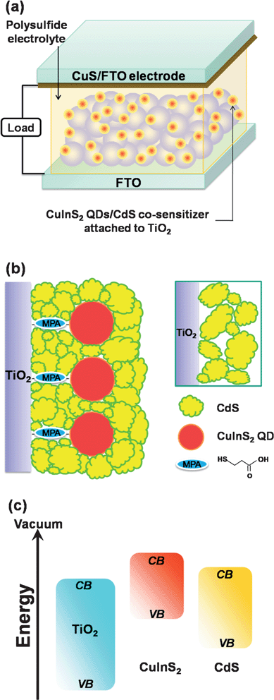 | ||
| Fig. 1 (a) Schematic illustration of the quantum dot-sensitized solar cell, which consists of a TiO2 nanocrystalline film sensitized with CuInS2-QDs/CdS as the photoanode, a CuS film, deposited on a SnO2:F coated glass (FTO) substrate, as the counter electrode, and a polysulfide electrolyte. (b) A conceptual schematic of the CuInS2-QDs/CdS heterostructure on the TiO2 surface. The inset illustrates the particle-packing network of a CdS film without the CuInS2 QD pillars. Note that coating ZnS to finalize the SILAR deposition is important for passivating the light-absorbing CuInS2-QDs/CdS sensitizers. (c) A schematic showing the relative band energy levels for charge transfer in the TiO2/CuInS2-QDs/CdS/ZnS electrode. ZnS is included because the function of ZnS coating is to passivate the sensitizers. | ||
Experimental
Materials
Copper(I) chloride (CuCl, 99.995%), indium(III) chloride (InCl3, 99.999%), 3-mercaptopropionic acid (MPA, 99+%), sodium sulfide (Na2S, 98+%), tetramethylammonium hydroxide (97+%), titanium chloride (TiCl4, 98+%), potassium chloride (KCl, 99.5%) and oleylamine (OA, 70%) were purchased from Sigma-Aldrich (USA). Cadmium nitrate (99+%) and sulfur (99.999%) were obtained from Acros (USA). TiO2 powder (P25, a mixed phase of 70% anatase and 30% rutile; average size 30 nm) from Degussa (Japan) was used to prepare TiO2 anatase nanoparticles for photoelectrodes. Polyethylene glycol (PEG; 20000 in molecular weight) and ethyl cellulose from Fluka (Germany) were used to suspend TiO2 particles in viscous solutions. Zinc nitrate (Zn(NO3)2·6H2O, 99.5%) and copper(II) nitrate (Cu(NO3)2·2.5H2O, 99.7%) were supplied by J. T. Baker (USA). Hexane (99.9%) and methanol (99.9%) were purchased from Tedia (USA), and ethanol (99.5%) was obtained from Merck (Germany). All the materials were used without further purification.Preparation of CuS counter electrodes
A mask, with a window encompassed by a commercially available 3M scotch tape (810DX 3/4′′), was used to define the active area of CuS electrodes (1.3 × 1.3 cm2). 0.5 M Cu(NO3)2 methanol solution (ca. 1 mL) was first dropped on a cleaned conducting glass substrate (SnO2:F coated glass, FTO; Hartford Glass TEC7, USA). A doctor-blade method, similar to that employed to spread the TiO2 suspensions in DSSCs, was used to remove the excess Cu(NO3)2 solution, and to obtain a thin layer of Cu(NO3)2 on the FTO. 1 mL of 1 M Na2S water–methanol solution (1![[thin space (1/6-em)]](https://www.rsc.org/images/entities/char_2009.gif) :
:![[thin space (1/6-em)]](https://www.rsc.org/images/entities/char_2009.gif) 1 volume ratio) was uniformly dropped on the Cu(NO3)2 decorated FTO. Upon dropping, copper and sulfur ions reacted rapidly, and the color immediately changed from blue (of Cu(II)) to brown, implying the formation of the CuS. The remainder of nitrate and sodium ions, and non-reacted Na2S and Cu(NO3)2, were rinsed away by deionized water, and then dried by an air-gun under the atmosphere conditions. The two-step dropping, rinse, and drying procedures are regarded as one deposition cycle of CuS. The incorporated amount of CuS can be increased by repeating the assembly cycles.
1 volume ratio) was uniformly dropped on the Cu(NO3)2 decorated FTO. Upon dropping, copper and sulfur ions reacted rapidly, and the color immediately changed from blue (of Cu(II)) to brown, implying the formation of the CuS. The remainder of nitrate and sodium ions, and non-reacted Na2S and Cu(NO3)2, were rinsed away by deionized water, and then dried by an air-gun under the atmosphere conditions. The two-step dropping, rinse, and drying procedures are regarded as one deposition cycle of CuS. The incorporated amount of CuS can be increased by repeating the assembly cycles.
Preparation of colloidal CuInS2 QDs
Solvothermal synthesis was used to synthesize CuInS2 QDs.37,51 First, 0.99 mg CuCl (0.01 mmol) and 2.2 mg InCl3 (0.01 mmol) were dissolved in 0.198 mL OA at room temperature. The resulting mixture was then heated to 120 °C, and maintained for 1 h with vigorous magnetic stirring, to form a clear mixture. This mixture was added, with magnetic stirring, to a Teflon-lined stainless steel autoclave (200 mL in capacity) containing 30 mL of hexane. A sulfur solution (1 mmol dissolved in 1 mL OA) was injected into the above mixture. Nucleation and subsequent growth of CuInS2 QDs were carried out in a sealed autoclave at a temperature of 110 °C for 1 h. After the autoclave was cooled to room temperature, the products were washed, and centrifuged with an ethanol–methanol (1![[thin space (1/6-em)]](https://www.rsc.org/images/entities/char_2009.gif) :
:![[thin space (1/6-em)]](https://www.rsc.org/images/entities/char_2009.gif) 2, v/v) solution. The resultant OA-capped QDs were dispersed in hexane for storage.
2, v/v) solution. The resultant OA-capped QDs were dispersed in hexane for storage.
For the subsequent self-assembly of CuInS2 QDs on the TiO2 electrodes, the OA ligands on the QDs were exchanged with MPA, which is a bifunctional linker molecule containing carboxylic acid and thiol groups. In the exchange with MPA, dried OA-capped CuInS2 QDs were dispersed in a methanol solution of MPA (60 mM) and tetramethylammonium hydroxide (70 mM),52 and the mixture was then sonicated for 30 min to obtain a clear dispersion of MPA-capped CuInS2 QDs. The MPA-capped QDs were precipitated by the addition of ethyl acetate/hexane (12/50, v/v) solution, and redispersed in methanol.
Fabrication of the CuInS2-QDs/CdS/ZnS QDSSC
The configuration of TiO2 on the photoanode was made of a compact underlayer, a transparent mesoporous layer (phase-pure anatase with particle size of 20 nm), and a scattering layer (ca. 400 nm) at the top. The compact layer was deposited by immersing the FTO substrate in an aqueous TiCl4 solution (40 mM) at 70 °C for 30 min, followed by rinsing with deionized water and ethanol.53 The synthesis of TiO2 suspensions employed in the transparent, and scattering layers and the detailed procedures of constructing the mesoporous TiO2 electrodes, are described in our previous report.37,54,55 The thickness of the mesoporous electrodes was approximately 15 μm (11 μm of transparent layer and 4 μm of scattering layer), measured by a surface profiler (Tencor Alpha-step 500 (USA)).The mesoporous TiO2 electrodes were subsequently sensitized with CuInS2 QDs and CdS by self-assembly and SILAR, respectively. For CuInS2 QD self-assembly, the TiO2 electrodes were heated to ∼110 °C and immersed in an acetonitrile solution of MPA (1 M) and sulfuric acid (0.1 M) for 12 h.56 Pre-treatment of MPA modification on the TiO2 surface can facilitate the CuInS2 QD adsorption. The electrodes were then thoroughly rinsed with methanol before being transferred to the CuInS2 QD solution. The MPA-modified TiO2 films were left in the MPA-capped QD–methanol solution for 24 h to ensure saturated entrapment of the QDs onto the TiO2 electrodes. For the in situ growth of CdS layers, the TiO2/CuInS2-QD electrode was successively dipped into 0.05 M Cd(NO3)2–methanol, rinsing methanol, 0.05 M Na2S–methanol, and rinsing methanol solution. The dipping time in the Cd2+ and S2− solution was 30 s for each, and the SILAR cycle was repeated 11 times. All the electrodes analyzed in this study have been coated with ZnS, carried out by one SILAR cycle consisting of twice dipping alternatively in the 0.2 M Zn(NO3)2 and 0.2 M Na2S solutions for 1 min per dip. The QDSSC was assembled with the QD-sensitized photoanodes and the CuS counter electrodes, maintaining a distance of 60 μm between them by using Surlyn (Solaronix SX1170-60, Swiss) as the spacer and injecting the polysulfide electrolyte, containing 2 M Na2S, 2 M S, and 0.2 M KCl, in the water–methanol solution (3![[thin space (1/6-em)]](https://www.rsc.org/images/entities/char_2009.gif) :
:![[thin space (1/6-em)]](https://www.rsc.org/images/entities/char_2009.gif) 7 by volume). The area of the cells was 0.16 cm2.
7 by volume). The area of the cells was 0.16 cm2.
Measurements
Scanning electron microscopic (SEM) images were obtained using a Jeol JSM-6700F (Japan), at a beam potential of 10 kV. UV-vis absorption spectra were recorded using a Hitachi U-4100 (Japan) spectrophotometer. The crystal structure of the counter electrode samples was characterized by powder X-ray diffraction (XRD), using a Rigaku RINT-2000 (Japan) diffractometer equipped with Cu-Kα radiation, excited at 40 kV and 40 mA. Transmission electron microscopy (TEM; Hitachi H-7500, Japan) and high-resolution TEM (HRTEM; FEI Tecnai G2 F20, USA) were used to explore the microstructure of the QDs. The samples for TEM and HRTEM analysis were prepared by placing a drop of a QD solution on a carbon film-coated nickel grid, where the CuInS2 QDs and the CuInS2-QDs/CdS co-sensitized TiO2 nanoparticles were dispersed in hexane and ethanol, respectively. X-Ray photoelectron spectrum (XPS) measurements were recorded with a Kratos Axis Ultra DLD X-ray photoelectron spectroscope, using monochromated Al Kα radiation at 75 W and a passing energy of 40 eV as the excitation source. The binding energies of the core levels were calibrated against a C 1s binding energy set at 284.6 eV. Electrochemical impedance spectroscopy (EIS) measurements were carried out with an impedance analyzer (Zahner IM6, Germany) at zero bias potential, and an AC potential amplitude of 10 mV over the frequency range of 0.02–105 Hz. A symmetric configuration consisting of two identical electrodes and the polysulfide electrolyte was used in the EIS measurements.35,57,58 Potentiostatic current–voltage polarization curves for the Pt, Au, and CuS electrodes were recorded using the Zahner IM6 analyzer in a three-electrode system with a Pt-gauze counter and an Ag/AgCl reference.Photocurrent–voltage characteristics (J–V curves) of QDSSCs were recorded under illumination with a solar simulator (Newport, Oriel class A, SP91160A, USA) at 100 mW cm−2 (AM 1.5G), using an electrochemical analyzer (CH Instruments 614B, USA). The intensity of the simulated light was calibrated using a reference Si solar cell. All the measurements were conducted under ambient conditions, with no antireflective layer. The incident photon to current conversion efficiencies (IPCE) of the QDSSCs was measured by the DC mode method, using an IPCE analyzer (Enlitech QE-R3011, Taiwan). In the measurement of open-circuit voltage decay, samples were illuminated steadily with simulated AM 1.5G at 100 mW cm−2, and the decay was studied as a function of time after the light was switched off.
Results and discussion
Characterization of the TiO2/CuInS2-QDs/CdS/ZnS electrode
Fig. 2a shows the transmission electron microscopy (TEM) image of the CuInS2 QDs used in TiO2 sensitization. The particle size was 3.5 ± 0.4 nm. The inset of Fig. 2a shows that the oleylamine-capped CuInS2–hexane dispersion has an orange color, indicating absorption of a great proportion of visible light. Fig. 2b shows the TEM image of TiO2 nanoparticles, co-sensitized with CuInS2-QDs/CdS. The sensitizers sufficiently cover the nanocrystalline TiO2 network with a thickness of 5–8 nm. The high-resolution TEM (HRTEM) image of the TiO2/CuInS2-QDs/CdS composite (Fig. 2c) clearly depicts the crystalline lattice fringes of the involved species. The lattice spacing distance of 0.351 nm, illustrated in the right zone of the image, corresponds to the (101) plane of anatase TiO2. The lattices with spacing distances of 0.320 and 0.335 nm around the TiO2 particle correspond to the (112) plane of the tetragonal CuInS2 (JCPDS file no. 85-1575) and (111) plane of the cubic CdS (JCPDS file no. 80-0019), respectively. The CdS coating by SILAR has a polycrystalline structure (encompassed by yellow lines), and is in close contact with both the CuInS2 QDs (encompassed by red lines) and TiO2 particles. | ||
| Fig. 2 (a) TEM image of the as-prepared CuInS2 QDs grown at 110 °C for 1 h. Inset shows the oleylamine-capped CuInS2-QDs–hexane dispersion, with an orange color. (b) TEM image of TiO2 nanocrystals sensitized with CuInS2-QDs/CdS. (c) HRTEM image of TiO2/CuInS2-QDs/CdS composite. The CuInS2 QDs and CdS sensitizers are encompassed by red and yellow lines, respectively. | ||
Fig. 3 shows the absorption spectra of the naked TiO2 film, and the TiO2 films sensitized with CuInS2 QDs, CdS or CuInS2-QDs/CdS. The naked TiO2 film absorbs only UV light (wavelengths of <420 nm). After sensitization the absorption spectra of the TiO2 films extend to the visible light region. The absorption of the TiO2/CuInS2 electrode occurs at approximately 650 nm, by a distinct blue-shift relative to that of bulk CuInS2 (ca. 830 nm).59 The absorption onset for TiO2/CdS occurs at approximately 580 nm. The TiO2/CuInS2-QDs/CdS electrode exhibits a red-shifted absorption onset at approximately 780 nm after CdS coating. As the CdS layer has an absorption onset at 580 nm, the red-shift must result from the light absorption of the CuInS2 QDs. This red-shift may indicate that the QD charge carrier wave functions tunnel into the surrounding CdS shell, as the conduction and valence band edge levels of CuInS2 QDs and CdS are close,59,60 thereby reducing the confinement energy, resulting in a red-shift in the absorption spectra.
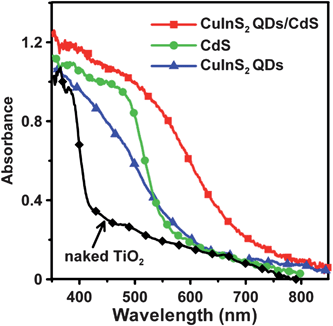 | ||
| Fig. 3 Optical absorption spectra of the naked nanocrystalline TiO2 film, and the TiO2 films sensitized with CuInS2 QDs, CdS, and CuInS2-QDs/CdS. | ||
In the photovoltaic performance assessment, the co-sensitized TiO2/CuInS2-QDs/CdS photoelectrodes (coated with a final ZnS layer) were incorporated with a polysulfide electrolyte, and a Pt or Au counter electrode, to form sandwich-type QDSSCs. The performance was poor because the charge transfer efficiency (or the electrocatalytic activity) of Pt or Au in the polysulfide electrolyte was unsatisfactory (see Figs. S1 and S2 of the ESI).†18,57 To improve the activity of the counter electrode, a nanocrystalline CuS film was deposited on the FTO substrate to replace the Pt and Au deposits.
Development of the CuS counter electrode
Successive ionic solution coating and reaction (SISCR) deposition was used to deposit CuS films as the counter electrode, and the growth mechanism of the CuS nanocrystals was monitored with scanning electron microscopy (see Fig. S3 of the ESI).† Complete coverage of the FTO substrate by a CuS layer, which consists of nanoparticles of 30–80 nm in size, can be obtained by increasing the deposition cycle to 4. The copper–sulfur aqueous chemistry is complex, as several stable and metastable phases of varying stoichiometries exist between ideal compositions of Cu2S and CuS.61,62Fig. 4 illustrates the XRD pattern of the nanocrystalline CuS layer from 4 cycle SISCR deposition. The main diffraction peaks are identical to those of the hexagonal phase CuS (JCPDS file no. 79-2321), justifying the formation of CuS nanocrystals from SISCR. The Cu ion of the sample is identified to be in the CuS state by using XPS (see Fig. S4 of the ESI).†63–66 Both XRD and XPS analyses confirm that the films obtained from SILAR deposition are nanocrystalline CuS.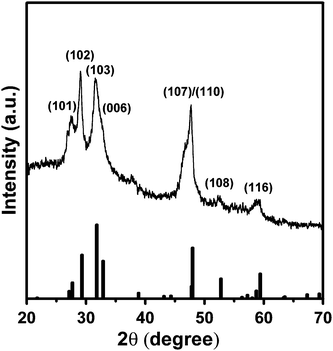 | ||
| Fig. 4 X-Ray diffraction (XRD) pattern of the 4-cycle SISCR CuS film indexed to the pure hexagonal phase. The standard pattern of CuS (JCPDS file no. 79-2321) is provided at the bottom. | ||
The CuS electrodes were subjected to analysis with EIS for charge transfer resistance (Rct) values in the polysulfide electrolyte (see Fig. S5 of the ESI).† The Rct between the electrode and the polysulfide electrolyte decreases with increasing deposition cycles, and after 4 deposition cycles, becomes stabilized at 4.2 Ω cm2. In comparison to the Pt and Au electrodes, the CuS electrodes exhibited a significantly lower Rct for interaction with the polysulfide electrolyte. Fan et al. fabricated ordered multimodal porous carbon (OMPC) to serve as the counter electrode in CdS/CdSe-based QDSSCs, and due to the unique ordered hierarchical nanostructure, demonstrated a very low Rct toward the polysulfide electrolyte (3.5 Ω cm2) for the OMPC electrode.58 However, Nernst diffusion impedance of the electrolyte appeared in the corresponding impedance spectra, due to the porous framework of the OMPC electrode. The CuS electrodes, developed in this study, have comparably low Rct values, and do not display any perceivable pore diffusion impedance for the electrolyte.
Fig. 5 shows the potentiostatic current–voltage polarization curves of the Pt, Au, and the CuS electrodes in the polysulfide electrolyte. The current induced by polarization directly gives the electrocatalytic activity of the electrodes. The polarization measurements show that the CuS electrodes outperform the Pt and Au electrodes in the polysulfide electrolyte. As to the effect of the CuS deposition cycle number, the 4-cycle SISCR CuS electrode has the highest polarization current, in accordance with the Rct results obtained from EIS. Therefore, based on the current–voltage polarization curve and EIS measurements, it is viable to use the CuS electrodes as the counter for QDSSCs, to replace conventional Pt or Au electrodes.
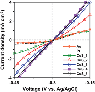 | ||
| Fig. 5 Potentiostatic current–voltage polarization curves of the Pt and Au electrodes and the CuS electrodes from varying SISCR cycles in the polysulfide electrolytes. | ||
Performance of QDSSCs based on CuS counter electrodes
Fig. 6 shows the photocurrent–voltage characteristics (J–V curves) of the QDSSCs, using CuS electrodes of varying SISCR cycles as the counter electrode. In comparison to the results of using the Pt and Au electrodes (Fig. S1 of the ESI),† the CuS electrodes significantly improved the photocurrent and open-circuit voltage of QDSSCs. The photocurrent increases with each CuS deposition cycle, and reaches a maximum at 4 cycles; therefore, further deposition does not increase the photocurrent. The photocurrent variation conforms to the trend of Rct (Fig. S5 of the ESI)† and polarization current (Fig. 5) for the counter electrodes. Table 1 summarizes the performance indices of the cells, based on the data of Fig. 6. Both Jsc and FF increase with each deposition cycle, and reach a maximum at 4 cycles, whereas Voc remains relatively invariant. The QDSSCs can reach an η maximum of 4.20%, primarily due to the increase in Jsc and FF. The above results indicate that the Rct (or the electrocatalytic activity) of the counter electrodes governs the Jsc and FF values, and therefore the conversion efficiency of the QDSSCs. The CuS counter electrodes achieved an FF value of 0.45, while Pt or Au produced a value of ∼0.3 (Fig. S1 of the ESI).† However, a QDSSC assembled with CuS-based counter electrodes has the potential to obtain an even higher FF value, via modification of the CuS structure or deposition method.45 Further studies are planned, along with a more detailed investigation into the correlation between the structure of the CuS-based electrode and the FF value. As the SISCR deposition of 4 cycles is the optimal process for CuS counter electrodes, the following discussion on the synergistic effects considers only the QDSSCs assembled with the 4-cycle CuS electrode.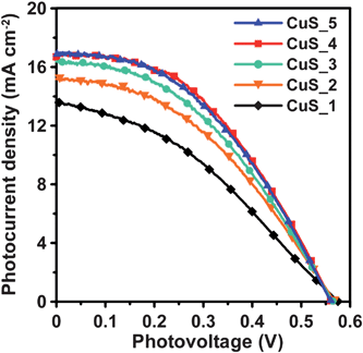 | ||
| Fig. 6 Photocurrent–voltage characteristics of QDSSCs assembled with the TiO2/CuInS2-QDs/CdS/ZnS photoanode and the CuS counter electrodes from varying SISCR cycles under AM1.5-type solar illumination at 100 mW cm−2. | ||
| Photoanode | Counter | V oc (V) | J sc (mA cm−2) | FF | η (%) |
|---|---|---|---|---|---|
| CuInS2-QDs/CdS | CuS_1 | 0.575 | 13.6 | 0.36 | 2.83 |
| CuInS2-QDs/CdS | CuS_2 | 0.568 | 15.2 | 0.41 | 3.52 |
| CuInS2-QDs/CdS | CuS_3 | 0.564 | 16.3 | 0.41 | 3.83 |
| CuInS2-QDs/CdS | CuS_4 | 0.560 | 16.9 | 0.45 | 4.20 |
| CuInS2-QDs/CdS | CuS_5 | 0.560 | 17.0 | 0.44 | 4.15 |
| CuInS2 QDs | CuS_4 | 0.354 | 1.56 | 0.56 | 0.31 |
| CdS | CuS_4 | 0.490 | 8.06 | 0.46 | 1.80 |
Synergistic effects of CuInS2-QDs/CdS co-sensitization
Fig. 7 shows the comparison of the J–V characteristics for the CuInS2 QDs-, CdS-, and CuInS2-QDs/CdS-sensitized cells that were incorporated with the 4-cycle CuS electrode. The data for the CuInS2-QDs/CdS-sensitized cell are extracted from Fig. 6 for comparison. Table 1 also lists the performance indices of the CuInS2 QDs- and CdS-sensitized cells. The cells that were sensitized with individual CuInS2 QDs or CdS are inferior in performance to the cell co-sensitized with CuInS2-QDs/CdS. The Jsc value was 16.9 mA cm−2 for the CuInS2-QDs/CdS-sensitized cell, whereas the values were 1.56 and 8.06 mA cm−2 for the CuInS2 QDs- and CdS-sensitized cells, respectively. The lower Jsc of the CuInS2 QDs cell, relative to that of the CdS cell, can be attributed to the sparser QD coverage on the TiO2 surface and the more defected surface of the QDs. Fig. 3 illustrates that the TiO2/CdS electrode exhibits a stronger optical absorption spectrum than the TiO2/CuInS2-QDs. Denser sensitizer coverage not only absorbs more incident photons, but also inhibits recombination of photogenerated charges with the electrolyte. Previous studies reported that SILAR deposition can form a closely-packed layer on TiO2 surface, while using a bifunctional linker to attach QDs results in low surface coverage.14,67 Coating CdS on the TiO2/CuInS2-QDs surface prominently improved the Jsc to 16.9 mA cm−2, a value comparable to that of ruthenium dye-based DSSCs.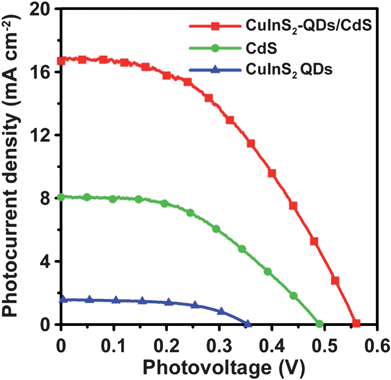 | ||
| Fig. 7 Photocurrent–voltage characteristics of QDSSCs assembled with the 4-cycle SISCR CuS counter electrode and various photoanodes including the electrodes sensitized with CuInS2-QDs, CdS, and CuInS2-QDs/CdS, all coated with a final ZnS layer, under AM1.5-type solar illumination at 100 mW cm−2. | ||
In the CuInS2-QDs/CdS-sensitized cell, the CdS sensitizer's contribution to Jsc should be no more than the Jsc value of the CdS-sensitized cell (8.06 mA cm−2). This indicates that the contribution from the CdS-coated CuInS2 QDs is at least 8.84 mA cm−2 (=16.9 mA cm−2–8.06 mA cm−2). The CuInS2 QDs-sensitized cell had a low Jsc value of 1.56 mA cm−2, and the CdS coating prominently increased the Jsc value of CuInS2 QDs to 8.84 mA cm−2. The extended absorption spectrum (Fig. 3), caused by the quantum confinement reduction with the CdS coating, should have contributed to the photocurrent increase, but cannot account for the entire enhancement as the photon absorption increase was not as high as the photocurrent increase. Thus, the CdS coating may have passivated the QDs' surface and suppressed the charge recombination or the electron leakage to the electrolyte. The role of CdS in surface passivation of the CuInS2 QDs may be one of the critical mechanisms for enhancing the Jsc value. Note that the final coating of ZnS on the photoelectrodes is essential because it passivates the CdS layer and promotes the cell performance (see Fig. S6 of the ESI for the J–V characteristics of the CuInS2-QDs/CdS-sensitized cell without ZnS coating).†
To clarify how the absorption spectrum widening and surface passivation effects, resulting from co-sensitization, can affect the quantum efficiency, we subjected the cells to IPCE analysis at varying excitation wavelengths. The IPCE characteristics of the cells (Fig. 8) are consistent with their absorption spectra (Fig. 3). The IPCE value increases significantly with co-sensitization, and the IPCE value of the co-sensitized cell is larger than the IPCE sum total of the other two cells. This proves that the surface passivation mechanism promotes the charge injection into TiO2. The CuInS2-QDs/CdS cell has a maximum IPCE of 78% at 510 nm, whereas the maximum IPCE values were only 17% for the CuInS2 QDs cell at 360 nm, and 43% for the CdS cell at 450 nm. An IPCE value of approximately 80% is one of the highest IPCE values obtained for QDSSCs.18,20,45,68 The co-sensitization extends the IPCE response spectrum from 600 nm or less (for the cells with individual CuInS2 QDs or CdS) to 800 nm or above. Although the IPCE values are considerably lower at wavelengths near 800 nm, the wide photon conversion spectrum, which has higher IPCE values than that of typical CdS/CdSe-sensitized QDSSCs at wavelengths above 700 nm,23,69 can explain the high Jsc of 16.9 mA cm−2 achieved in this study. The contribution to IPCE at longer wavelengths arises from the light absorption of CuInS2 QDs, and not CdS, as CdS is not photoactive to the photons with smaller energy. This demonstrates the occurrence of reduction of the quantum confinement in the CuInS2 QDs, as observed in the absorption spectra (Fig. 3).
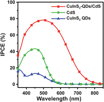 | ||
| Fig. 8 IPCE spectra of QDSSCs assembled with the 4-cycle SISCR CuS counter electrode and various photoanodes including the electrodes sensitized with CuInS2-QDs, CdS, and CuInS2-QDs/CdS, all coated with a final ZnS layer, measured as a function of incident light wavelength. | ||
This study also estimated the short-circuit photocurrents from the integrated IPCE spectra (Fig. 8) and obtained values of 4.1 and 13 mA cm−2 for the CdS- and CuInS2-QDs/CdS-sensitized cells. These short-circuit photocurrents are smaller than the Jsc values obtained from the J–V measurements under one-sun (AM 1.5G) illumination (Fig. 7). The discrepancy can be attributed to the highly defected feature of the CuInS2-QDs and CdS deposited on TiO2. In the IPCE measurements, the monochromatic light intensities were much lower than that of AM 1.5G illumination and charge separation and collection are more efficient at high illumination intensities.4,45 This effect is especially significant for the CdS-sensitized cell at wavelengths longer than 550 nm as the IPCE result shows negligibly small values while the absorption is rather active.
In addition to enhancing Jsc, Fig. 7 shows that coating CdS on the TiO2/CuInS2-QDs electrode significantly increases Voc. The Voc values for different sensitizers show an order of CuInS2 QDs (0.354 V) < CdS(0.490 V) < CuInS2-QDs/CdS (0.560 V). The Voc value is closely related to the recombination of charges at the TiO2 surface. Fig. 9 shows the dark current–voltage curves for the cells. The dark current onset voltage had an order identical to that for the Voc value. This confirms that charge recombination on TiO2 influences the Voc value. SILAR deposition of CdS can provide a higher TiO2 surface coverage than CuInS2 QDs, and the CdS-sensitized cell shows a higher dark current onset voltage than the CuInS2 QDs-sensitized cell. The CuInS2-QDs/CdS-sensitized cell had a higher dark current onset voltage than that of the CdS cell, indicating that the TiO2 surface coverage of the former is higher. The result suggests that the first linked CuInS2 QDs may have increased the TiO2 surface energy (by increasing the surface roughness) to improve the degree of CdS attachment on the surface. Fig. 1b shows the conceptual schematic of the sensitizer nanoarchitecture, in which CdS nanocrystals are closely packed around the linked CuInS2 QD pillars. Without the pillars, the CdS formed by SILAR shows a loose packing network that is less resistant to recombination. This surface covering strategy resulted in an insulated TiO2 surface, and therefore a high Voc value for the consequent cell.
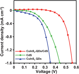 | ||
| Fig. 9 Dark current–voltage characteristics of QDSSCs assembled with the 4-cycle SISCR CuS counter electrode and various photoanodes including the electrodes sensitized with CuInS2-QDs, CdS, and CuInS2-QDs/CdS, all coated with a final ZnS layer. | ||
To further explore the recombination mechanism on the photoelectrode, the cells were subjected to open-circuit voltage decay analysis, which can obtain the time that the electrons reserve in the conduction band of TiO2 (that is, the lifetime τn). Fig. 10a shows the variation of Voc with time for the cells illuminated to a steady state voltage, with subsequent interruption of illumination. The voltage decay with time gives the electron lifetime according to70,71
 | (1) |
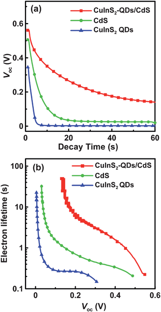 | ||
| Fig. 10 (a) The variation of open-circuit voltage (Voc) decay with time and (b) the dependence of electron lifetime on Voc for QDSSCs assembled with the 4-cycle SISCR CuS counter electrode and various photoanodes including the electrodes sensitized with CuInS2-QDs, CdS, and CuInS2-QDs/CdS, all coated with a final ZnS layer. The QDSSCs were illuminated at 100 mW cm−2 before measuring the Voc decay in the dark. | ||
Conclusions
A QDSSC assembled with a TiO2/CuInS2-QDs/CdS/ZnS photoanode and a CuS counter electrode results in a Jsc of 16.9 mA cm−2, Voc of 0.56 V, and η of 4.20% under one-sun illumination. The TiO2 sensitization strategy, which includes attaching CuInS2 QDs with a bifunctional linker followed by SILAR coating of CdS, constructs a structured sensitizing layer that consists of CdS nanocrystals closely packed around the earlier-linked CuInS2 QDs, which serve as the pillars of the layer. The heterojunction between CdS and CuInS2 resulted in reduction of quantum confinement in the CuInS2 QDs, and therefore extended the optical absorption spectrum. The CdS coating may also play a role in surface passivation of the CuInS2 QDs, to suppress the recombination of photogenerated charges. Due to the quantum confinement reduction and surface passivation effects, the CuInS2-QDs/CdS-sensitized cell showed a wide IPCE action spectrum (ranging to 800 nm), and a peak conversion efficiency of nearly 80% at 510 nm. These synergistic effects of co-sensitization, along with the high electrocatalytic activity of the CuS counter electrode, resulted in the high Jsc value of the cell. The intimate coverage of CdS on TiO2 surface reduces the recombination of photogenerated electrons with electrolyte, and thus increases the Voc value. This study presents a sensitization strategy that simultaneously exploits the benefits of semiconductor heterojunction and creates an intimate coverage on TiO2 surface for high Jsc and Voc values. By a further reduction of the series resistance of cells for higher FF values, this sensitization strategy has the potential of advancing the QDSSC performance to a level comparable to that of DSSCs.Acknowledgements
This research is supported by the National Science Council of Taiwan (100-3113-E-007-008 and 98-2221-E-006-112-MY2), and the Bureau of Energy, Ministry of Economic Affairs, Taiwan (100-D0204-2).References
- P. V. Kamat, J. Phys. Chem. C, 2007, 111, 2834–2860 CAS.
- T. F. Yeh, J. M. Syu, C. Cheng, T. H. Chang and H. Teng, Adv. Funct. Mater., 2010, 20, 2255–2262 CrossRef CAS.
- C. C. Hu and H. Teng, J. Phys. Chem. C, 2010, 114, 20100–20106 CAS.
- K. P. Wang and H. Teng, Phys. Chem. Chem. Phys., 2009, 11, 9489–9496 RSC.
- P. T. Hsiao, M. D. Lu, Y. L. Tung and H. Teng, J. Phys. Chem. C, 2010, 114, 15625–15632 CAS.
- C.-Y. Chen, M. Wang, J.-Y. Li, N. Pootrakulchote, L. Alibabaei, C. Ngoc-le, J. D. Decoppet, J.-H. Tsai, C. Grätzel, C.-G. Wu, S. M. Zakeeruddin and M. Grätzel, ACS Nano, 2009, 3, 3103–3109 CrossRef CAS.
- A. J. Nozik, Phys. E., 2002, 14, 115–120 CrossRef CAS.
- P. V. Kamat, J. Phys. Chem. C, 2008, 112, 18737–18753 CAS.
- G. Hodes, J. Phys. Chem. C, 2008, 112, 17778–17787 CAS.
- W. U. Huynh, J. J. Dittmer and A. P. Alivisatos, Science, 2002, 295, 2425–2427 CrossRef CAS.
- R. D. Schaller and V. I. Klimov, Phys. Rev. Lett., 2004, 92, 186601 CrossRef CAS.
- M. Shalom, I. Hod, Z. Tachan, S. Buhbut, S. Tirosh and A. Zaban, Energy Environ. Sci., 2011, 4, 1874–1878 CAS.
- S. H. Im, H. J. Kim, S. W. Kim, S. W. Kim and S. I. Seok, Energy Environ. Sci., 2011, 4, 4181–4186 Search PubMed.
- I. Mora-Seró, S. Giménez, F. Fabregat-Santiago, R. Gómez, Q. Shen, T. Toyoda and J. Bisquert, Acc. Chem. Res., 2009, 42, 1848–1857 CrossRef.
- S. Buhbut, S. Itzhakov, E. Tauber, M. Shalom, I. Hod, T. Geiger, Y. Garini, D. Oron and A. Zaban, ACS Nano, 2010, 4, 1293–1298 CrossRef CAS.
- L. M. Peter, K. G. U. Wijayantha, D. J. Riley and J. P. Waggett, J. Phys. Chem. B, 2003, 107, 8378–8381 CrossRef CAS.
- J. H. Bang and P. V. Kamat, ACS Nano, 2009, 3, 1467–1476 CrossRef CAS.
- S. Giménez, I. Mora-Seró, L. Macor, N. Guijarro, T. Lana-Villarreal, R. Gómez, L. J. Diguna, Q. Shen, T. Toyoda and J. Bisquert, Nanotechnology, 2009, 20, 295204 CrossRef.
- N. Guijarro, T. Lana-Villarreal, I. Mora-Seró, J. Bisquert and R. Gómez, J. Phys. Chem. C, 2009, 113, 4208–4214 CAS.
- A. Salant, M. Shalom, I. Hod, A. Faust, A. Zaban and U. Banin, ACS Nano, 2010, 4, 5962–5968 CrossRef CAS.
- H. Lee, M. K. Wang, P. Chen, D. R. Gamelin, S. M. Zakeeruddin, M. Grätzel and M. K. Nazeeruddin, Nano Lett., 2009, 9, 4221–4227 CrossRef CAS.
- C. H. Chang and Y. L. Lee, Appl. Phys. Lett., 2007, 91, 053503 CrossRef.
- Y. L. Lee and Y. S. Lo, Adv. Funct. Mater., 2009, 19, 604–609 CrossRef.
- D. R. Baker and P. V. Kamat, Adv. Funct. Mater., 2009, 19, 805–811 CrossRef CAS.
- H. M. Pathan and C. D. Lokhande, Bull. Mater. Sci., 2004, 27, 85–111 CrossRef CAS.
- R. Vogel, K. Pohl and H. Weller, Chem. Phys. Lett., 1990, 174, 241–245 CrossRef CAS.
- Q. Shen, J. Kobayashi, L. J. Diguna and T. Toyoda, J. Appl. Phys., 2008, 103, 084304 CrossRef.
- S. Gorer and G. Hodes, J. Phys. Chem., 1994, 98, 5338–5346 CrossRef CAS.
- M. Shalom, S. Dor, S. Ruhle, L. Grinis and A. Zaban, J. Phys. Chem. C, 2009, 113, 3895–3898 CAS.
- L. J. Diguna, Q. Shen, J. Kobayashi and T. Toyoda, Appl. Phys. Lett., 2007, 91, 023116 CrossRef.
- M. Shalom, S. Ruhle, I. Hod, S. Yahav and A. Zaban, J. Am. Chem. Soc., 2009, 131, 9876–9877 CrossRef CAS.
- A. Zaban, O. I. Mićić, B. A. Gregg and A. J. Nozik, Langmuir, 1998, 14, 3153–3156 CrossRef CAS.
- P. Yu, K. Zhu, A. G. Norman, S. Ferrere, A. J. Frank and A. J. Nozik, J. Phys. Chem. B, 2006, 110, 25451–25454 CrossRef CAS.
- A. Tubtimtae, K. L. Wu, H. Y. Tung, M. W. Lee and G. J. Wang, Electrochem. Commun., 2010, 12, 1158–1160 CrossRef CAS.
- H. J. Lee, P. Chen, S.-J. Moon, F. Sauvage, K. Sivula, T. Bessho, D. R. Gamelin, P. Comte, S. M. Zakeeruddin, S. Il Seok, M. Grätzel and M. K. Nazeeruddin, Langmuir, 2009, 25, 7602–7608 CrossRef CAS.
- K. T. Kuo, D. M. Liu, S. Y. Chen and C. C. Lin, J. Mater. Chem., 2009, 19, 6780–6788 RSC.
- T. L. Li, Y. L. Lee and H. Teng, J. Mater. Chem., 2011, 21, 5089–5098 RSC.
- S. A. Sapp, C. M. Elliott, C. Contado, S. Caramori and C. A. Bignozzi, J. Am. Chem. Soc., 2002, 124, 11215–11222 CrossRef CAS.
- H. J. Lee, J.-H. Yum, H. C. Leventis, S. M. Zakeeruddin, S. A. Haque, P. Chen, S. Il Seok, M. Grätzel and M. K. Nazeeruddin, J. Phys. Chem. C, 2008, 112, 11600–11608 CAS.
- Y. Tachibana, H. Y. Akiyama, Y. Ohtsuka, T. Torimoto and S. Kuwabata, Chem. Lett., 2007, 36, 88–89 CrossRef CAS.
- L. Li, X. Yang, J. Gao, H. Tian, J. Zhao, A. Hagfeldt and L. Sun, J. Am. Chem. Soc., 2011, 133, 8458–8460 CrossRef CAS.
- G. Hodes, J. Manassen and D. Cahen, J. Electrochem. Soc., 1980, 127, 544–549 CrossRef CAS.
- B. Miller and A. Heller, Nature, 1976, 262, 680–681 CrossRef CAS.
- Z. Yang, C. Y. Chen, C. W. Liu and H. T. Chang, Chem. Commun., 2010, 46, 5485–5487 RSC.
- Z. Yang, C. Y. Chen, C. W. Liu, C. L. Li and H. T. Chang, Adv. Energy Mater., 2011, 1, 259–264 CrossRef CAS.
- V. González-Pedro, X. Xu, I. Mora-Seró and J. Bisquert, ACS Nano, 2010, 4, 5783–5790 CrossRef.
- S.-R. Jang, R. Vittal and K.-J. Kim, Langmuir, 2004, 20, 9807–9810 CrossRef CAS.
- K. Imoto, K. Takahashi, T. Yamaguchi, T. Komura, J. Nakamura and K. Murata, Sol. Energy Mater. Sol. Cells, 2003, 79, 459–469 CrossRef CAS.
- T. N. Murakami, S. Ito, Q. Wang, M. K. Nazeeruddin, T. Bessho, I. Cesar, P. Liska, R. Humphry-Baker, P. Comte, P. Pechy and M. Grätzel, J. Electrochem. Soc., 2006, 153, A2255–A2261 CrossRef CAS.
- B. Fang, S.-Q. Fan, J. H. Kim, M.-S. Kim, M. Kim, N. K. Chaudhari, J. Ko and J.-S. Yu, Langmuir, 2010, 26, 11238–11243 CrossRef CAS.
- T. L. Li and H. Teng, J. Mater. Chem., 2010, 20, 3656–3664 RSC.
- K. S. Leschkies, R. Divakar, J. Basu, E. Enache-Pommer, J. E. Boercker, C. B. Carter, U. R. Kortshagen, D. J. Norris and E. S. Aydil, Nano Lett., 2007, 7, 1793–1798 CrossRef CAS.
- S. Ito, P. Chen, P. Comte, M. K. Nazeeruddin, P. Liska, P. Péchy and M. Grätzel, Progr. Photovolt.: Res. Appl., 2007, 15, 603–612 CrossRef CAS.
- P. T. Hsiao, K. P. Wang, C. W. Cheng and H. Teng, J. Photochem. Photobiol., A, 2007, 188, 19–24 CrossRef CAS.
- C. C. Tsai and H. Teng, Chem. Mater., 2006, 18, 367–373 CrossRef CAS.
- A. Kongkanand, K. Tvrdy, K. Takechi, M. Kuno and P. V. Kamat, J. Am. Chem. Soc., 2008, 130, 4007–4015 CrossRef CAS.
- S.-Q. Fan, B. Fang, J. H. Kim, J.-J. Kim, J.-S. Yu and J. Ko, Appl. Phys. Lett., 2010, 96, 063501 CrossRef.
- S.-Q. Fan, B. Fang, J. H. Kim, B. Jeong, C. Kim, J.-S. Yu and J. Ko, Langmuir, 2010, 26, 13644–13649 CrossRef CAS.
- S. B. Zhang, S.-H. Wei and A. Zunger, J. Appl. Phys., 1998, 83, 3192–3196 CrossRef CAS.
- R. Vogel, P. Hoyer and H. Weller, J. Phys. Chem., 1994, 98, 3183–3188 CrossRef CAS.
- R. H. Kore, J. S. Kulkarni and S. K. Haram, Chem. Mater., 2001, 13, 1789–1793 CrossRef CAS.
- M. Orphanou, E. Leontidis, T. K. Leodidou, P. Koutsoukos and K. C. Kyriacou, Langmuir, 2004, 20, 5605–5612 CrossRef CAS.
- A. Tang, S. Qu, K. Li, Y. Hou, F. Teng, J. Cao, Y. Wang and Z. Wang, Nanotechnology, 2010, 21, 285602 CrossRef.
- M. Sam, M. R. Bayati, M. Mojtahedi and K. Janghorban, Appl. Surf. Sci., 2010, 257, 1449–1453 CrossRef CAS.
- C. D. Wagner, Faraday Discuss. Chem. Soc., 1975, 60, 291–300 RSC.
- L. Chen, J. Chen, H. Zhou, L. Liu and H. Wan, Mater. Lett., 2007, 61, 1974–1977 CrossRef CAS.
- I. Mora-Seró, V. Likodimos, S. Giménez, E. Martínez-Ferrero, J. Albero, E. Palomares, A. G. Kontos, P. Falaras and J. Bisquert, J. Phys. Chem. C, 2010, 114, 6755–6761 Search PubMed.
- Q. Zhang, X. Guo, X. Huang, S. Huang, D. Li, Y. Luo, Q. Shen, T. Toyoda and Q. Meng, Phys. Chem. Chem. Phys., 2011, 13, 4659–4667 RSC.
- H. J. Lee, J. Bang, J. Park, S. Kim and S.-M. Park, Chem. Mater., 2010, 22, 5636–5643 CrossRef CAS.
- P. T. Hsiao and H. Teng, J. Taiwan Inst. Chem. Eng., 2010, 41, 676–681 CrossRef CAS.
- Z. Liu, M. Miyauchi, Y. Uemura, Y. Cui, K. Hara, Z. Zhao, K. Sunahara and A. Furube, Appl. Phys. Lett., 2010, 96, 233107 CrossRef.
Footnote |
| † Electronic supplementary information (ESI) available: The J–V curves of QDSSCs assembled with the TiO2/CuInS2-QDs/CdS/ZnS photoanode and Pt or Au counter electrodes under one-sun illumination; Nyquist impedance plots of Au and Pt electrodes in the polysulfide electrolyte; SEM images of the CuS nanocrystalline films deposited with varying SISCR cycles; Cu 2p XPS spectra of the CuS film; Nyquist impedance plots of the CuS electrodes in the polysulfide electrolyte; the J–V curves of a QDSSC assembled with a CuInS2-QDs/CdS-sensitized photoanode without ZnS coating, and the 4-cycle SISCR CuS counter electrode under one-sun illumination. See DOI: 10.1039/c1ee02253a |
| This journal is © The Royal Society of Chemistry 2012 |
