 Open Access Article
Thermally encapsulated phenothiazine@MWCNT cathode for aqueous zinc ion battery†
Noufal Merukan
Chola
 ab and
Rajaram K.
Nagarale
 *ab
*ab
aMembrane Science and Separation Technology Division, CSIR-Central Salt and Marine Chemicals Research Institute, Bhavnagar, 364002 Gujarat, India
bAcademy of Scientific and Innovative Research (AcSIR), Ghaziabad – 201002, India
First published on 11th April 2022
Abstract
Phenothiazine is a p-type cathode that follows the anion pairing mechanism, where the electrode undergoes extensive expansion and contraction during cycling, which deleteriously affects the battery performance. Herein, we tried to improve the electrode stability without compensating the electrical conductivity and the redox properties of the material. We followed the low-temperature solution-phase thermal encapsulation of the molecules inside the multi-walled carbon nanotubes (MWCNT). This method effectively improved the electrical conductivity, inhibited the massive loss of the active material, and alleviated the adverse effects on the cathode. The initial specific capacitance for the neat phenothiazine was found to be 145.2 mA h g−1 at the current density of 100 mA g−1versus Zn/Zn2+. The electrode was modified by low-tsemperature solution-phase thermal encapsulation and the specific capacities were found to be 239.5, 177.1, 151.1, 123.5, 90.0, 42.02 mA h g−1 at the respective current densities of 50, 100, 200, 300, 400 and 500 mA g−1. The battery performance was further improved by suppressing dendrite formation at the anode using an ethylene glycol additive. In 2000 charging-discharging cycles at a current density of 300 mA g−1, the encapsulated material with a 1![[thin space (1/6-em)]](https://www.rsc.org/images/entities/char_2009.gif) :
:![[thin space (1/6-em)]](https://www.rsc.org/images/entities/char_2009.gif) 1 water ethylene glycol mixture showed a specific capacity of 123.5 mA h g−1. Thus, we inferred that low-temperature thermal encapsulation is an efficient, non-destructive, and green method for acquiring excellent electrode stability for small organic molecules.
1 water ethylene glycol mixture showed a specific capacity of 123.5 mA h g−1. Thus, we inferred that low-temperature thermal encapsulation is an efficient, non-destructive, and green method for acquiring excellent electrode stability for small organic molecules.
Introduction
Energy storage devices are a very promising emerging technology that can replace intermittent fossil fuels. Lithium-ion-based batteries are well established in the market and are used extensively in portable and wearable electronic devices. Having a considerably small radius, with outstanding transport number and specific ionic size, Li-ions are vastly explored for application in rechargeable batteries.1–4 Despite these excellent features, a few of their challenging issues constrain their applications. The use of highly inflammable organic electrolytes, environmental benignity, and limited resources are a few of the problems with Li batteries.5–10 Numerous studies have been conducted to address these issues and to also find alternative metal-based batteries. Aqueous zinc ion batteries are a very promising alternative. Their abundant precursors, user-friendliness, being unreactive in an aqueous medium (unlike Li metal), and comparatively good energy densities (gravimetric 820 mA h g−1 and volumetric 5855 mA h cm−3) make zinc-ion-based energy devices very promising but they have not been well-explored. Zinc metal offers, as an anode, very low reduction potential (−0.76 V vs. SHE) compared to other metals in an aqueous system and it possesses a two-electron mechanism that essentially increases the energy density of the battery.11–13Many inorganic cathode materials like oxides of manganese, vanadium, iron, and others such as Prussian blue, etc., have been reported for aqueous zinc ion batteries.14 The reversible (de)insertion of relatively large hydrated zinc ions is difficult to accommodate inside the specific lattice structures of these materials. Their tend to be irreversible lattice changes that result in the deterioration of the battery performance.15 Organic molecules, on the other hand, are a very promising alternative. They offer the benefits of (1) being the most abundant low molecular weight elements that directly affect the cost, availability, and safety of the battery; (2) following a simple charge storage mechanism; (3) no complicated lattice structures like those in inorganic materials where lattice structures collapse after prolonged cycling; (4) enormous choice of smart molecular engineering, functional group introduction and/or interconversion, covalent linkage to the polymer and/or secondary substrate for enhanced electrode stability, potential tuning, hydrophilicity, and flexibility.16–18 Unfortunately, studies on organic cathodes are still in the early stages. Quinone and quinone derivatives,19 nitrile group-containing compounds,20 and conducting polymers such as PANI21 and PEDOT22 are some of the organic cathodes reported so far. Phenothiazine shows excellent redox chemistry with a remarkable positive potential with metal ion (de)insertion. Unlike the other common organic redox molecules, it shows excellent electrical conductivity.23 With suitable substitution on the C-7 and C-4 carbons, the potential can be very effectively tuned. Introducing alkyl groups on the N–H would facilitate access to the two electrons by stabilizing the cation radical as the transition state intermediate.24 Such N-substituted phenothiazine could deliver a theoretical energy density of ∼1000 W h kg−1 with a 4 V average cell potential vs. Li/Li+ through a two-electron oxidation–reduction mechanism.25 Due to its ‘p’-type nature, which follows anion (de)insertion and/or ion pairing, the electrode is suitable for most metal-based batteries, such as Li+, Na+, K+, Zn2+, etc.26 The anion (de)insertion and/or reversible ion-pairing mechanism causes the contraction/expansion of the phenothiazine-based cathode surface. The continuous shrinkage and growth of the electrode surface deleteriously affect the cell performance.27–29 Such detrimental effects can be solved by integrating the phenothiazine molecules with porous hyper-cross-linked polymers. The availability of the large number of pores can effectively inhibit the adverse effects during the cycling process because of the localized buffering effect in the pores. However, the electrical conductivity was detrimentally affected because of the non-conducting porous polymers, even though the excessive dissolution and the shrinking of the material during cycling have been rectified.30 Bar et al. reported N-substituted palladium-catalyzed polymer networks of phenothiazine to restrict the extensive dissolution in the electrolyte.31 Even though they could solve the dissolution problem, the electrical conductivity of the electrode was poor. Similar metal–organic frameworks (MOF) and redox molecules-based covalent organic frameworks (COF) have been identified due to their specific pore structures but poor electrical conductivity limited their utility in battery applications.32 The specific capacity of the organic molecules depends on the number of redox-active centers on the molecules; the higher the number of active groups, the greater the capacity of the battery. Therefore, reduced theoretical capacities for COF-based electrode materials have been reported.33 From the above discussion, it is clear that electrical and ionic conductivities would be equally important while designing the cathode material.
We developed a promising methodology for getting these aforementioned cathode properties by the low-temperature solution-phase encapsulation of functional materials into an electronic conducting matrix such as carbon nanotubes. P. Ajayan and S. Ijima first experimentally introduced thermal migration of the molten metal particles inside the high-temperature-treated carbon nanotubes.34 Subsequently, many reports were published on the thermal encapsulation of the small organic molecules,35 metal particles36 and fullerenes.37,38 Kataura et al. experimentally demonstrated the insertion of fullerenes and non-fullerene materials into the nanotubes forming ‘peapod’-like structures.39 Similarly, Taishi Takenobu et al. reported the encapsulation of small organic molecules in CNTs by thermal annealing for application in molecular electronics.35 A chemical method of CNT opening and filling was reported using concentrated nitric acid where uncontrolled structural disruption was noticed due to the highly corrosive nitric acid.37,40 Smith et al. experimentally demonstrated the simultaneous CNT synthesis and C60 trapping inside the nanotubes.38 Encapsulation of functionalized endohedral fullerenes inside the thin-layered CNT was reported where the complex dynamic behavior of the intercalants was identified.41 Ugarte et al. proved the thermal intercalation of the molten silver particles inside the CNTs by capillary forces, and the decomposition of silver nitrate inside the nanotubes to form the chains of the silver nanobeads.32
Herein, we report the solution phase low-temperature thermal encapsulation of phenothiazine in MWCNTs to address the issue of cathode dissolution and dendrite formation at the anode. Upon heating, we observed that the nanotubes can be uncapped and the small molecules or particles can be irreversibly intercalated via the process of capillary suction without compromising the electrochemical properties. Further, the modified electrolyte containing an ethylene glycol water mixture (1![[thin space (1/6-em)]](https://www.rsc.org/images/entities/char_2009.gif) :
:![[thin space (1/6-em)]](https://www.rsc.org/images/entities/char_2009.gif) 1 ratio), effectively facilitated the solvation of Zn2+ ions inhibiting [Zn(H2O)6]2+ complex formation that improved the cycling stability of the electrode over prolonged cycling experiments.
1 ratio), effectively facilitated the solvation of Zn2+ ions inhibiting [Zn(H2O)6]2+ complex formation that improved the cycling stability of the electrode over prolonged cycling experiments.
Materials and methods
General physical characterization
FTIR spectra were recorded for functional group identification with a PerkinElmer (Germany) GXFTIR system in the 400–4000 cm−1 range using the KBr pellet method. The XRD diffraction patterns were recorded with a PAN Analytical (Germany) system using the Cu Kα line (λ = 1.5406 Å) between 2° to 60° at a scan rate of 2° min−1. The surface morphology was visualized using a JSM-7100F (Japan), field emission scanning electron microscope. Transmission electron microscopy imaging was performed using an FEI-Titan G2 60-300 kV TEM equipped with a high-brightness Schottky-field emission electron source, a high-resolution Gatan Imaging Filter (GIF), and X-ray energy dispersive spectrometer (EDS) using lacey-carbon-supported copper TEM grids. For STEM, an Annular Bright-Field (ABF) detector was used for the detailed chemical composition analysis. For optical imaging, an Axio Imager M1 SZX-16 Stereo zoom microscope was used with a Galilean Optical System and SZX2-EEPA extendable eye-point adjuster in a zoom ratio of 0.7x–11.5x. Raman spectroscopy was performed using a LabRAM HR Evolution Horiba Jobin Yvon Raman spectrometer with a laser excitation wavelength of 785 nm in a frequency range of 400–3500 cm−1. UV-Vis absorption spectra were recorded on a Shimadzu Corp 80109 UV-Vis spectrophotometer using a quartz cuvette. X-Ray photoelectron spectroscopy was done using a Thermo Fischer Scientific ESCALAB XI+ with an Al Kα (hν = 1486.6 eV) X-ray source with a base vacuum-operated at 300 W. Electrochemical studies were carried out using a CHI 760E Electrochemical Analyzer (CH Instrument, USA). Galvanostatic charging-discharging experiments were performed using a multi-channel battery testing system (Neware-BTS 610) at room temperature. All commercially available chemicals were used without further purification.Experimental
Preparation of MWCNTs-encapsulated phenothiazine (Pheno@CNT)
The preparation method was according to a procedure previously reported by our group.42 Here, 300 mg MWCNTs were heated at 300 °C in a muffle furnace in a thermally resistant silica crucible for 30 minutes and immediately added to a prepared DMSO solution containing phenothiazine (1.2 g) and stirred overnight, filtered, and washed thoroughly with copious amounts of DMSO, methanol, acetone, and water. The product was dried in a vacuum oven at 60 °C and used for electrochemical and spectroscopic studies.Preparation of the electrode
For cathode preparation, the active electrode material and multi-walled carbon nanotubes and Nafion solution were ground in a 6![[thin space (1/6-em)]](https://www.rsc.org/images/entities/char_2009.gif) :
:![[thin space (1/6-em)]](https://www.rsc.org/images/entities/char_2009.gif) 3
3![[thin space (1/6-em)]](https://www.rsc.org/images/entities/char_2009.gif) :
:![[thin space (1/6-em)]](https://www.rsc.org/images/entities/char_2009.gif) 1 weight ratio and mixed using a mortar and pestle. The well-mixed black powder was dispersed in isopropyl alcohol, sonicated and ball milled for the homogeneous dispersion of the material of fine particles. The paste was drop-coated on a glassy carbon (GC) electrode for cyclic voltammetry studies and dip-coated on carbon paper for battery charging/discharging experiments. The cathode preparation with Pheno@CNT was a similar process, except that the ratio of Pheno@CNT and Nafion solution was 9
1 weight ratio and mixed using a mortar and pestle. The well-mixed black powder was dispersed in isopropyl alcohol, sonicated and ball milled for the homogeneous dispersion of the material of fine particles. The paste was drop-coated on a glassy carbon (GC) electrode for cyclic voltammetry studies and dip-coated on carbon paper for battery charging/discharging experiments. The cathode preparation with Pheno@CNT was a similar process, except that the ratio of Pheno@CNT and Nafion solution was 9![[thin space (1/6-em)]](https://www.rsc.org/images/entities/char_2009.gif) :
:![[thin space (1/6-em)]](https://www.rsc.org/images/entities/char_2009.gif) 1.
1.
For anode preparation, zinc foil was washed with acetone, 1 M H2SO4, DI water and dried. It was polished with P1200 grit size sandpaper for a shiny surface. The cyclic voltammograms were recorded in 2 M ZnSO4 with zinc as the counter and reference electrodes and glassy carbon as the working electrode.
Results and discussion
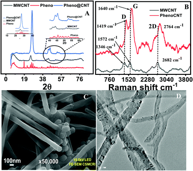
The encapsulation of phenothiazine inside the MWCNTs is associated with the thermally activated capillary suction and thermo-migration. The friendly host–guest interaction is based on the assumption that π electron clouds are present in the carbon nanotubes and intercalants at the molecular level through π–π stacking, dipole–dipole and dipole–induced dipole interactions. The encapsulation was confirmed by XRD, FESEM and HRTEM analysis. From the powder X-ray diffraction pattern, the presence of distinctive signals at diffraction angles 26.9, 43.7, 45.5, 53.0 and 54.7° confirmed the formation of pheno@CNT. The peaks for neat MWCNTs appeared at diffraction angles of 25.42, 42.2, 43.9, 51.4, and 53.2° (Fig. 1A). Lattice strain caused by the intermolecular host-guest interaction resulted in a significant positive peak shift after encapsulation.43 More precisely, the peak shift in the XRD pattern was attributed to the following: (i) changes in stoichiometric composition, (ii) microstructure parameters (changes in crystalline size and lattice strain), (iii) thermal annealing imparted residual stress on the nanotubes;44i.e., when the nanocomposites were under tension stress all peaks shifted to higher diffraction angles. The stress was due to the linkage between the host and guest or the change in the size of the host by the encapsulation process, and the change in the binding energy of the sample.Raman spectral analysis of pheno@cnt showed very clear ‘D’ and ‘G’ bands at 1419 cm−1 and 1640 cm−1, respectively (Fig. 1B). For pristine MWCNTs, the corresponding peaks were observed at 1346 cm−1 and 1572 cm−1. The difference in peak position was ∼17 cm−1, i.e. a red shift due to the π–π* charge transfer.35 Raman spectra of the pristine materials along with the encapsulation-modified material further suggested successful encapsulation (Fig. S3, ESI†). Close inspection of the FESEM images indicated the absence of particle aggregation on the surface of the MWCNTs and confirmed the uniform distribution of phenothiazine inside and interlayers of MWCNTs (Fig. 1C). With transmission electron microscopy imaging, the encapsulation was irrevocably confirmed (Fig. 1D). The uncapping or rupturing of the side-wall of the MWCNTs and their complete structural collapse were not observed during thermal treatment. The TEM images showed the stability of MWCNTs to thermal shock. Intercalants were observed inside the CNTs, confirming the successful encapsulation (Fig. S2, ESI†). STEM mapping showed the expected constituent elements of the intercalant inside the carbon nanotubes Fig. S1 (ESI†). The presence of sulfur and nitrogen in the energy dispersive X-ray spectrum was due to the parent phenothiazine molecules, confirming the encapsulation.
Electrochemical study
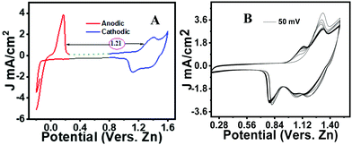
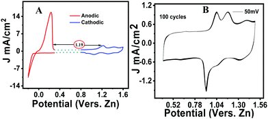
An initial cyclic voltammetry (CV) study was carried out for the neat phenothiazine versus zinc in a 2 M ZnSO4 solution. Typical cathodic and anodic peaks were observed, respectively, at 1.13 V and 0.9 V with a distinct ΔE value of 115 mV (Fig. S4, ESI†). The peak difference from zinc to phenothiazine was identified as ∼1.21 V to make an organic–zinc battery of ∼1 V (Fig. 2A). However, in a multiple CV scan, the current was found to be considerably decreasing over time due to the excessive dissolution of the active material in the electrolyte (Fig. 2B). The CV curves at different scan rates show the systematic increase in the peak current with the increase in the scan rate (Fig. S5, ESI†). Linearity was observed when the peak current was plotted versus the square root of the scan rate according to the Randles–Sevcik equation.45 The obtained straight line indicates that the charge storage mechanism was predominantly due to the diffusion-controlled process, not by the non-faradaic surface-confined phenomenon (inset Fig. S5, ESI†).The voltammogram of pheno@cnt was recorded under similar experimental conditions. Compared to the neat phenothiazine, pheno@cnt showed broad oxidation/reduction peaks with similar peak potential (Fig. 3A). The potential difference between the oxidation/reduction of zinc and pheno@cnt was found to be 1.19 V, which is the output cell voltage. The change in the peak current was due to the change in ion transport, which was explained by the dual ion-pairing mechanism. Charge storage occurs through the shuttling of the anions and cations, respectively, on the cathode and anode counterparts. The diffusion rate of anion shuttling on the modified cathode would be seemingly much higher than that of the neat phenothiazine electrode. This would reduce the electrostatic inter-ionic interactions between the Zn2+ ions and SO42− ions from the bulk towards the corresponding electrodes to a considerable extent, resulting in a broad peak with high current density. Nanosizing of the electrodes also provides a promising explanation: (i) it provides spacious accommodation for the insertion/desertion of the shuttling ion, which would essentially improve the cycle life; (ii) the higher electrode–electrolyte contact area causes a fast charging/discharging process; (iii) the short ion-path length for electronic conductivity is due to the extensive π-orbital conjugation; (iv) the high surface area can reversibly accommodate large counter anions with no serious disruption of the electrode.46 CNT-based electrode materials have been found with excellent electrochemical performance because of their robustness, outstanding chemical stability, much better electrical conductivity, and specific porous tubular structural characteristics. MWCNTs are very peculiar in providing opportunities for nano-scale engineering created by the self-assembly of molecules inside the hollow cores. It has been experimentally demonstrated by Kataura et al. that fullerenes and non-fullerene-type materials can be inserted into the nanotubes forming ‘peapod’-like structures.39 Takenobu et al. reported the encapsulation of small organic molecules in CNTs by a thermal annealing method for application in molecular electronics.35 A chemical method of CNT opening and filling was reported via concentrated nitric acid treatment.37 Smith et al. experimentally demonstrated the simultaneous CNT synthesis and C60 trapping inside the nanotubes.47 Encapsulation of functionalized endohedral fullerenes inside the thin layered CNT was reported where the complex dynamic behavior of the intercalants was identified.48 Ugarte et al. proved the thermal intercalation of the molten silver particles inside the CNTs by capillary forces, and the decomposition of silver nitrate inside the nanotubes to form the chains of the silver nanobeads.32 Low-temperature thermal encapsulation of newly synthesized ferrocene-based organic cathode was recently reported by our group. The cycling stability, rate performance, and capacity retention were significantly improved after encapsulation.49 These reports clearly state that electrical conductivity and ionic conductivity are equally important for effective cathode materials. This explains why pheno@cnt has relatively high current density and sharp peaks even after 100 continuous cycles of CV experiments (Fig. 3B).
The voltammogram at the slow scan rate (Fig. S6B, ESI†) showed the oxidation of phenothiazine at 1.05 V and reduction at 1.12 V. The recorded voltammogram at different scan rates showed the synergistic contribution of the Faradaic diffusion mechanism and the non-faradaic surface-confined capacitive contribution with the dependence of the peak current on the scan rate. The capacitive current was due to the formation of the electrical double layer, imparted mostly by the MWCNT host. The contribution of the faradic current was imparted by the intercalant redox molecule and the non-faradaic storage mechanism by the host carbon nanotubes. From the power law, according to eqn (2) and (3), the peak current of the CV versus different sweeping scan rates, a plot of log (ip) versus log (scan rate) was obtained with slope ‘b’ and intercept ‘a’ (Fig. S6A inset, ESI†). The ‘b’ value is a significant deciding factor for whether the charge storage mechanism was following the diffusion process (if b ≤ 0.5) or the EDLC capacitive phenomenon (if b ≥ 0.5).21 The observed ‘b’ values were 0.72, 0.71 and 0.82, respectively for peaks 1, 2 and 3, which indicated that the synergistic contribution was from diffusion as well as capacitive storage mechanisms. The Pheno@cnt electrode was found to be exceptionally stable, as evident from the recorded multiple scan voltammogram, a hundred cycles at the 50 mV s−1 scan rate showed no change in the peak current (Fig. 3B).
| ip = a·vb | (2) |
log![[thin space (1/6-em)]](https://www.rsc.org/images/entities/char_2009.gif) ip = log ip = log![[thin space (1/6-em)]](https://www.rsc.org/images/entities/char_2009.gif) a + b·log a + b·log![[thin space (1/6-em)]](https://www.rsc.org/images/entities/char_2009.gif) v v | (3) |
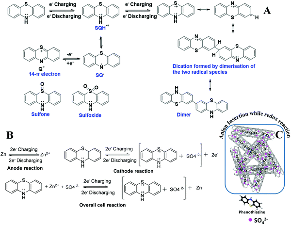
The solubility of the oxidized phenothiazine species was prevented by its encapsulation in MWCNTs. The semiquinone radical (SQH˙+) formed during the oxidation/reduction of pheno@cnt is also vulnerable to oxidation or disproportionation into the more favorable 14-π electron quinonic (Q+) cation system. However, the acceleration of anion insertion by the positively charged ‘N’ and ‘S’ atoms in the phenothiazine rings with the formation of “dual-ion pairing” prevents their disproportionation reaction as shown in Scheme 1B and C. Such a ‘dual ion’ mechanism was reported in the ‘p’-type cathodes such as Zn//PANI,53 Zn//polyindole54 systems, where the simultaneous intercalation of cations and anions into the respective electrodes occurs. Anions can be reversibly adsorbed by the conducting polymers depending on the charge generated on the heteroatoms. Since the cathode follows the ‘p’-type charge storage mechanism, anion insertion/deinsertion occurs on the cathode during the cycling process. Therefore, the possibility of the shrinkage and expansion of the cathode is obvious due to the continuous insertion/deinsertion of the large counter anions. However, by the uniform distribution of thermally encapsulated phenothiazine into spacious MWCNTs, the continuous expansion-shrinkage process by counter ion (de)insertion was effectively prevented.
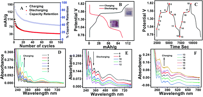
The battery performance of neat phenothiazine is presented in Fig. 4A. It shows the continuous decrease in the specific capacity by the dissolution of the active electrode material and/or self-coupling, polymerization, and irreversible chemical oxidation of the sulfur to sulfoxide (Scheme 1A)55 side reactions. The observed specific capacities were 145.2, 126, 110.99, 60.91 and 32.23 mA h g−1 at the respective current densities of 100, 150, 200, 300 and 400 mA g−1 Fig. S7 (ESI†). A very clear two hump reduction pathway was observed in the discharge profile, which substantiated the two peaks observed in the voltammogram. A distinct systematic color change of the electrolyte during the charging/discharging experiment was observed. Gradual color changes occurred, going from colorless to dark blue during charging, and blue to rose-colored when half discharged and then to colorless for complete discharge (Fig. 4B inset), in a typical two-step charging-discharging profile at low current density (Fig. 4B). During the charging/discharging at a point indicated by a red dot in Fig. 4C, the electrolyte was extracted and analyzed by UV visible spectroscopy. The oxidation was accompanied by the color change from colorless to dark blue involving a radical cation, whose presence was confirmed by the absorption at 532 nm. The slight absorption at 706 nm corresponds to the radical coupling to form a dimer with a face-to-face orientation Fig. 4D.56 At the initial point of charging, phenothiazine is insoluble in water, evident from the suppression of the absorption peak at 532 nm. This peak intensity increased as the charging continued, which was direct evidence that the material was slowly dislodged from the electrode surface (as the SHQ radical cation) after oxidation and underwent dissolution in the electrolyte. The gradual decrease (during discharging) and increase (during charging) of the peak at 532 nm were attributed to the variation of the radical concentration in the electrolyte Fig. 4E and F. The peaks at 420 nm are attributed due to the different electronic transitions between different energy levels such as σ–σ*, π–π* and n–π* by benzene rings as well as heteroatoms (S, NH) carrying lone pairs of electrons.
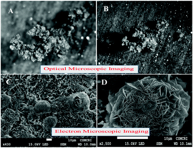
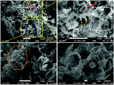
Stereo zoom SZX16 optical microscopic imaging was carried out to obtain visual images of the electrode surface at high magnification. Upon close inspection of the anode surface, massive dendrite growth was observed. As represented by Fig. 5A and B, we analyzed one of the selective dendrites on the zinc plate grown out of the plane, which was mostly responsible for the catastrophic short-circuit of the battery. The dendrite formation occurred at the non-uniform electrode surface where the current density was relatively high. Its formation was confirmed by FESEM images (Fig. 5C and D). The observation of the cathode surface revealed heavily aggregated thick mass deposition by self-coupled radical cations during the cycling experiment (Fig. 6), where heavy coral-like deposition was observed. The supporting optical images of the detached cathode surface after the fully charged (Fig. S8A–D, ESI†) and partially discharged state (Fig. S9A–C, ESI†) further confirmed the heavy aggregation of the material. This massive aggregation, which was presumably formed by self-coupling or partial polymerization, was dislodged into the electrolyte with long-time cycling. From the EDX elemental analysis of the cathode surface after the cycling experiment, the sulfur content was very high, which proved the SO42− anion insertion into the cathode Fig. S10 (ESI†).
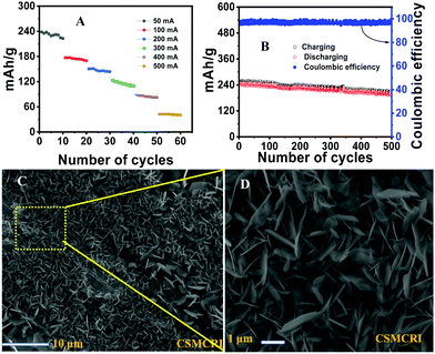
The galvanostatic charging/discharging experiment of the Pheno@CNT is shown in Fig. 7A at different current densities. The specific capacities were found to be 239.5, 177.1, 151.1, 123.5, 90.0, 42.02 mA h g−1 at the respective current densities of 50, 100, 200, 300, 400 and 500 mA g−1 with ten initial cycles for each. The capacity performance was much improved as compared to the neat phenothiazine with negligible capacity loss. Fig. 7B shows the charging–discharging capacity profile at 50 mA g−1 with an initial capacity of 239.5 mA h g−1, which retained 234.4 mA h g−1 after 100 cycles and remained at 197 mA h g−1 after a prolonged 500 cycles with 82.2% of the initial capacity retention and 98% coulombic efficiency. This substantial improvement in battery performance is due to the following factors: (i) spacious accommodation for the (de)insertion of the shuttling ions, (ii) higher electrode-electrolyte contact area causing a fast charging/discharging process, (iii) short path length for electronic conductivity because of the extensive π-orbital conjugation, (iv) high surface area that can reversibly accommodate large counter anions with no serious disruption of the electrode.57 Owing to the large surface area and excellent robust porous tubular networks, MWCNTs offer a large number of pores for accommodating the large counter anions. This imparts the easy transfer of SO42− ions for the (de)doping of the oxidized/reduced states of phenothiazine molecule while charging and discharging, hence leading to excellent stability.
The enhanced stability was incurred by the partial suppression of dendrite formation at the anode, evident from the hexagonal plate-type structures (FESEM images Fig. 7C and D). The anode surface was free from the formation of the protuberant dendrites formation (Fig. S12, ESI†). However, the complete suppression of the dendrite formation is a real challenge. It is associated with the non-uniform distribution of current on the zinc anode surface. Mechanistically, the dendrite formation is due to the localized Zn2+ ion deposition, nucleation and subsequent growth on the electrode surface. Many efforts have been made to suppress the dendrite formation, such as electrodeposited zinc anodes, polymer additives such as polyethylene glycol, polyacrylamide, polyvinyl butyral, and the addition of inorganic materials such as fumed silica, acetate salts, etc., to the electrolyte.58–60 Solvated zinc ions exist as [Zn (H2O)6]2+ in the electrolyte. This generates a large number of water molecules in close proximity to the electrode during zinc deposition or charging. These active water molecules can likely trigger the H2 evolution reaction, which causes a considerable pH decrease in the periphery of the zinc foil. This can perpetuate the dendrite formation and also promote the Zn(OH)2 and ZnO deposition, which is ‘dead’ zinc.61 Numerous reports have addressed the stability of the aqueous zinc battery, enhancing the working stability of the anode as well as the cathode. Electrochemically preparing the anode by zinc deposition, and a nanolayered solid electrolyte interface (SEI) on the zinc plates are a few of the well-established procedures that could ameliorate the excessive dendrite formation on the zinc surface during cycling experiments. Electrolyte modification is an important strategy to address the deleterious effect on the electrodes as well as the possibility of widening the working potential window. “Water-in-salt” is one such method for the simple use of super concentrated electrolytes in which the water content would be the minimum, which would essentially reduce the H2 evolution as well as the unwanted [Zn(H2O)6]2+ complex formation at the periphery of the electrodes.62 This H2 evolution would cause a reduction in the pH of the electrolyte, which would hasten the H2 evolution and consequently corrode the zinc anode. Ionic liquids are also an interesting class of electrolytes that reduce such unwanted side reactions during the cycling experiment. One of the striking observations in the ionic liquid-based electrolytes is that the formation of ZnO and basic zinc sulphate [Zn4SO4(OH)6·H2O] was completely hindered during the cycling experiment, whereas the neat ZnSO4 electrolyte has various forms of such hydrated salts.63 Excessive dendrite growth on the anode side was also observed perpendicular to the electrode surface, which penetrated the separator and consequently caused the catastrophic short-circuit of the cell. Organic electrolyte additives are also an important strategy for alleviating these parasitic reactions on the anode surface. Dimethyl carbonate (DMC) water mixture is an interesting electrolyte mixture that would form a solid electrolyte interface and essentially reduce the side reactions on the anode.64 Here, we have implemented the ethylene glycol (EG) water mixture in a 1![[thin space (1/6-em)]](https://www.rsc.org/images/entities/char_2009.gif) :
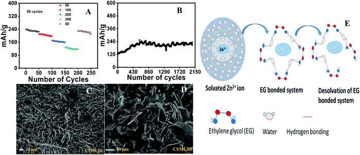
:![[thin space (1/6-em)]](https://www.rsc.org/images/entities/char_2009.gif) 1 ratio as a medium for the electrolyte. EG can effectively prevent the [Zn (H2O)6]2+ complex formation by extensive H-bonding with water molecules, which can effectively inhibit H2 evolution to a larger extent. Coordinated water molecules are more prone to undergo H2 evolution as compared to the ‘free’ water molecules as the bond energy of the O–H in the former system is considerably reduced, which accelerates the water-splitting reaction. The H2 evolution (HER; H2O + e− = ½ H2 + OH−) is mechanistically favorable as compared to the O2 evolution (OER; H2O = ½O2 + 2H+ + 2e−) due to the sluggish kinetics of the latter process.65 This essentially decreases the huge desolvation thermodynamic barrier of the hydrated zinc ions to a considerable extent and controls H2 evolution with the formation of specific solvation shells (Fig. 8E). It is also pertinent to point out that EG is an excellent fire retardant that can additionally help the battery by reducing the risk of inflammability. We performed the charging/discharging experiment under this condition and found that the capacity retention was greatly improved. The specific capacities of the battery were found to be 239.9, 210.6, 170.7 and 128.6 mA h g−1 at the respective current densities of 50, 100, 200 and 300 mA g−1 (Fig. 8A). The modified electrode exhibited excellent reversibility of the rate performance, which retained 96% of the initial capacity. Also, it was noticed that the capacity fading was effectively improved, 225.7 mA h g−1 after continuous fifty cycles against the initial capacity of 239.9 mA h g−1 at 50 mA g−1.
1 ratio as a medium for the electrolyte. EG can effectively prevent the [Zn (H2O)6]2+ complex formation by extensive H-bonding with water molecules, which can effectively inhibit H2 evolution to a larger extent. Coordinated water molecules are more prone to undergo H2 evolution as compared to the ‘free’ water molecules as the bond energy of the O–H in the former system is considerably reduced, which accelerates the water-splitting reaction. The H2 evolution (HER; H2O + e− = ½ H2 + OH−) is mechanistically favorable as compared to the O2 evolution (OER; H2O = ½O2 + 2H+ + 2e−) due to the sluggish kinetics of the latter process.65 This essentially decreases the huge desolvation thermodynamic barrier of the hydrated zinc ions to a considerable extent and controls H2 evolution with the formation of specific solvation shells (Fig. 8E). It is also pertinent to point out that EG is an excellent fire retardant that can additionally help the battery by reducing the risk of inflammability. We performed the charging/discharging experiment under this condition and found that the capacity retention was greatly improved. The specific capacities of the battery were found to be 239.9, 210.6, 170.7 and 128.6 mA h g−1 at the respective current densities of 50, 100, 200 and 300 mA g−1 (Fig. 8A). The modified electrode exhibited excellent reversibility of the rate performance, which retained 96% of the initial capacity. Also, it was noticed that the capacity fading was effectively improved, 225.7 mA h g−1 after continuous fifty cycles against the initial capacity of 239.9 mA h g−1 at 50 mA g−1.
In order to evaluate the electrolyte stability, we performed prolonged continuous cycling for 2000 cycles at 300 mA g−1 and the cell exhibited a specific capacity of 124.5 mA h g−1. The electrode showed ultra-stability even after 2000 cycles, which is due to the collective contribution of the modified electrolyte and electrode Fig. 8B. From the in-depth analysis of the electrode surface by FESEM, we further confirmed that the unwanted dendrite formation was greatly inhibited. Fig. 8C and D show the SEM images of the anode and cathode surfaces, respectively, where the formation of hexagonal plate-like structures was observed at the anode. This substantiates our assumption of a large H-bonding network offered by EG in the electrolyte. The uniform homogeneous distribution of the particles was confirmed by the stereo zoom optical images of the anode surface. From the energy dispersive X-ray diffraction spectrum of the cathode, we again confirmed the constituent elements of the intercalant molecules. (Fig. S10A–F, ESI†) From the assessment of the stereo zoom optical microscopic image of the anode (Fig. S11A and B, ESI†), we did not observe any sharp protuberant dendrites on the anode, unlike the electrode coated with neat material. These findings strongly support our assumption of the reduction of the huge desolvation penalty of the hydrated zinc ions by the addition of ethylene glycol.
The capacity performance was found to be much better than the previously reported organic cathodes for aqueous zinc batteries Fig. 9. A very recent report on phenothiazine attached to aniline (n/p type cathode) exhibited the specific capacitance of 188.24 mA h g−1.66 A few quinone-containing organic molecules as cathodes were also found to be less efficient as compared to our material. Cathodes of 1,2 and 1,4 naphthaquinone exhibited 68 and 149 mA h g−1, respectively, with considerable capacity fading for the zinc battery.19 To stabilize the quinone radicals, as well as control the dissolution and unwanted bifacial crystallization, we performed the ‘knitting type’ polymerization of the hydroquinone nuclei in our previous report.67 A detailed comparison of the reported small organic molecule-based cathodes was made, regarding cell performance, electrolytes used, and the associated mechanisms, and summarized in Table S1 (ESI†). Since MWCNTs are cost-effective, designing such host materials with good electronic and ionic conductivities and substantial thermal resistance would be a breakthrough for the large-scale production of this type of electrode material. It is also noteworthy that the smart molecular engineering over the nanotubes such as introducing heteroatoms inside the side-walls of the nano/microtubes, functionalized tubes, post-modification of the tubes by over-coating with highly conducting paste, etc., are some of the promising approaches to host design. We, therefore, propose this small molecule solution phase, low-temperature thermal intercalation as a general strategy in electrode material design to achieve improved electric as well as ionic conductivities and also to alleviate the side reactions without compromising the redox chemistry.
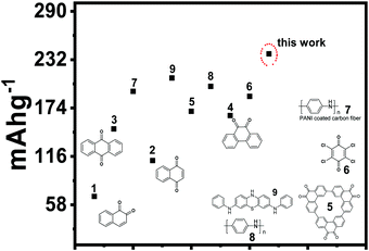 | ||
| Fig. 9 Comparison of the specific capacitancse of the reported organic cathodes for the zinc battery. | ||
Conclusion
Phenothiazine molecules possess very promising redox chemistry, which involves diverse unparalleled intermediates such as semi benzoquinone and quinone type radical species. They undergo radical self-coupling and serious side reactions such as polymerization, oxidation of sulfur to sulfone, then further to sulfoxide in addition to the extensive dissolution in the electrolyte. Since they belong to the ‘p’-type class of organic cathodes, anion insertion/expulsion occurs during the cycling process. Continuous expansion and shrinkage of the cathode surface deleteriously affect the electrochemical performances of the material. We have addressed these challenging constrains of phenothiazine by the low-temperature thermal intercalation inside the CNTs, as well as by the electrolyte modification with ethylene glycol addition. The initial specific capacity was 145.2 mA h g−1 at the current density of 100 mA g−1versus Zn/Zn2+. After thermal intercalation, it was considerably improved, with 239.5, 177.1, 151.1, 123.5, 90.0, 42.02 mA h g−1 at the respective current densities of 50, 100, 200, 300, 400, and 500 mA g−1. Through electrolyte modification with ethylene glycol, the ultra-stability of the electrode was achieved, which exhibited a specific capacity of 124.5 mA h g−1 at 300 mA g−1 current density, and the electrode was excellently stable after a prolonged charging/discharging experiment for 2000 cycles. With this, we conclude that low-temperature intercalation, as well as an ethylene glycol-modified electrolyte, would be an efficient method for addressing the common constraints observed in most of the small organic molecule-based electrodes.Conflicts of interest
There are no conflicts of interest to declare.Acknowledgements
Director, CSIR-CSMCRI is acknowledged for his tremendous support and inspiration. The divisional chair of MSST department and analytical & instrumentation facility of CSMCRI-CSIR Bhavnagar are also greatly acknowledged. Dr Vaibhav A. Mantri, chair of Applied Phycology and Biotechnology Division is greatly acknowledged for providing optical microscope facility. RKN thanks for the financial support, grant number 58/14/22/2019-BRNS from Board of Research in Nuclear Sciences, Department of Atomic Energy (DAE); and grant number EMR/2016/00l977 from Science and Engineering Research Board, DST India. CSIR-CSMCRI manuscript number 248/2021.References
- M. Armand and J. M. Tarascon, Building better batteries, Nature, 2008, 451(7179), 652–657, DOI:10.1038/451652a.
- J. B. Goodenough, Electrochemical energy storage in a sustainable modern society, Energy Environ. Sci., 2014, 7(1), 14–18, 10.1039/C3EE42613K.
- J. B. Goodenough, How we made the Li-ion rechargeable battery, Nat. Electron., 2018, 1(3), 204, DOI:10.1038/s41928-018-0048-6.
- J. Xie and Y. C. Lu, A retrospective on lithium-ion batteries, Nat. Commun., 2020, 11(1), 2499, DOI:10.1038/s41467-020-16259-9.
- A. Manthiram, A reflection on lithium-ion battery cathode chemistry, Nat. Commun., 2020, 11(1), 1550, DOI:10.1038/s41467-020-15355-0.
- J. M. Tarascon, Is lithium the new gold?, Nat. Chem., 2010, 2(6), 510, DOI:10.1038/nchem.680.
- Z. Zeng, V. Murugesan, K. S. Han, X. Jiang, Y. Cao, L. Xiao, X. Ai, H. Yang, J.-G. Zhang, M. L. Sushko and J. Liu, Non-flammable electrolytes with high salt-to-solvent ratios for Li-ion and Li-metal batteries, Nat. Energy, 2018, 3(8), 674–681, DOI:10.1038/s41560-018-0196-y.
- J. Kalhoff, G. G. Eshetu, D. Bresser and S. Passerini, Safer electrolytes for lithium-ion batteries: State of the art and perspectives, ChemSusChem, 2015, 8(13), 2154–2175, DOI:10.1002/cssc.201500284.
- B. Liu, Y. Jia, J. Li, S. Yin, C. Yuan, Z. Hu, L. Wang, Y. Li and J. Xu, Safety issues caused by internal short circuits in lithium-ion batteries, J. Mater. Chem. A, 2018, 6(43), 21475–21484, 10.1039/C8TA08997C.
- J. B. Goodenough and Y. Kim, Challenges for rechargeable batteries, J. Power Sources, 2011, 196(16), 6688–6694, DOI:10.1016/j.jpowsour.2010.11.074.
- G. Fang, J. Zhou, A. Pan and S. Liang, Recent advances in aqueous zinc-ion batteries, ACS Energy Lett., 2018, 3(10), 2480–2501, DOI:10.1021/acsenergylett.8b01426.
- Y. Li, J. Fu, C. Zhong, T. Wu, Z. Chen, W. Hu, K. Amine and J. Lu, Recent advances in flexible zinc-based rechargeable batteries, Adv. Energy Mater., 2019, 9(1), 1802605, DOI:10.1002/aenm.201802605.
- M. Du, Z. Miao, H. Li, Y. Sang, H. Liu and S. Wang, Strategies of structural and defect engineering for high-performance rechargeable aqueous zinc-ion batteries, J. Mater. Chem. A, 2021, 9(35), 19245–19281, 10.1039/D1TA03620C.
- H. Li, L. Ma, C. Han, Z. Wang, Z. Liu, Z. Tang and C. Zhi, Advanced rechargeable zinc-based batteries: Recent progress and future perspectives, Nano Energy, 2019, 62, 550–587, DOI:10.1016/j.nanoen.2019.05.059.
- N. Zhang, X. Chen, M. Yu, Z. Niu, F. Cheng and J. Chen, Materials chemistry for rechargeable zinc-ion batteries, Chem. Soc. Rev., 2020, 49(13), 4203–4219, 10.1039/C9CS00349E.
- P. Poizot, J. Gaubicher, S. Renault, L. Dubois, Y. Liang and Y. Yao, Opportunities and challenges for organic electrodes in electrochemical energy storage, Chem. Rev., 2020, 120(14), 6490–6557, DOI:10.1021/acs.chemrev.9b00482.
- T. B. Schon, B. T. McAllister, P.-F. Li and D. S. Seferos, The rise of organic electrode materials for energy storage, Chem. Soc. Rev., 2016, 45(22), 6345–6404, 10.1039/C6CS00173D.
- Y. Liang and Y. Yao, Positioning organic electrode materials in the battery landscape, Joule, 2018, 2(9), 1690–1706, DOI:10.1016/j.joule.2018.07.008.
- Q. Zhao, W. Huang, Z. Luo, L. Liu, Y. Lu, Y. Li, L. Li, J. Hu, H. Ma and J. Chen, High-capacity aqueous zinc batteries using sustainable quinone electrodes, Sci. Adv., 2018, 4(3), eaao1761, DOI:10.1126/sciadv.aao1761.
- N. M. Chola and R. K. Nagarale, TCNQ confined in porous organic structure as cathode for aqueous zinc battery, J. Electrochem. Soc., 2020, 167(10), 100552, DOI:10.1149/1945-7111/ab9cc9.
- C. Kim, B. Y. Ahn, T.-S. Wei, Y. Jo, S. Jeong, Y. Choi, I.-D. Kim and J. A. Lewis, High-power aqueous zinc-ion batteries for customized electronic devices, ACS Nano, 2018, 12(12), 11838–11846, DOI:10.1021/acsnano.8b02744.
- D. Bin, W. Huo, Y. Yuan, J. Huang, Y. Liu, Y. Zhang, F. Dong, Y. Wang and Y. Xia, Organic-inorganic-induced polymer intercalation into layered composites for aqueous zinc-ion battery, Chem, 2020, 6(4), 968–984, DOI:10.1016/j.chempr.2020.02.001.
- S. P. Massie, The chemistry of phenothiazine, Chem. Rev., 1954, 54(5), 797–833, DOI:10.1021/cr60171a003.
- N. H. Attanayake, J. A. Kowalski, K. V. Greco, M. D. Casselman, J. D. Milshtein, S. J. Chapman, S. R. Parkin, F. R. Brushett and S. A. Odom, Tailoring two-electron-donating phenothiazines to enable high-concentration redox electrolytes for use in nonaqueous redox flow batteries, Chem. Mater., 2019, 31(12), 4353–4363, DOI:10.1021/acs.chemmater.8b04770.
- B. M. Peterson, D. Ren, L. Shen, Y. C. M. Wu, B. Ulgut, G. W. Coates, H. D. Abruña and B. P. Fors, Phenothiazine-based polymer cathode materials with ultrahigh power densities for lithium ion batteries, ACS Appl. Energy Mater., 2018, 1(8), 3560–3564, DOI:10.1021/acsaem.8b00778.
- S. Lee, K. Lee, K. Ku, J. Hong, S. Y. Park, J. E. Kwon and K. Kang, Utilizing latent multi-redox activity of P-type organic cathode materials toward high energy density lithium-organic batteries, Adv. Energy Mater., 2020, 10(32), 2001635, DOI:10.1002/aenm.202001635.
- K. Lee, I. Serdiuk, G. Kwon, D. J. Min, K. Kang, S. Y. Park and J. E. Kwon, Energy Environ. Sci., 2020, 13, 4142–4156, 10.1039/D0EE01003K.
- T. R. Garrick, K. Kanneganti, X. Huang and J. W. Weidner, Modeling volume change due to intercalation into porous electrodes, J. Electrochem. Soc., 2014, 161(8), E3297–E3301, DOI:10.1149/2.030408jes.
- F. Otteny, M. Kolek, J. Becking, M. Winter, P. Bieker and B. Esser, Unlocking full discharge capacities of poly(vinylphenothiazine) as battery cathode material by decreasing polymer mobility through cross-linking, Adv. Energy Mater., 2018, 8(33), 1802151, DOI:10.1002/aenm.201802151.
- Y. Zhang, S. N. Riduan and J. Wang, Redox active metal- and covalent organic frameworks for energy storage: Balancing porosity and electrical conductivity, Chem. – Eur. J., 2017, 23(65), 16419–16431, DOI:10.1002/chem.201702919.
- T. Godet-Bar, J.-C. Leprêtre, O. Le Bacq, J.-Y. Sanchez, A. Deronzier and A. Pasturel, Electrochemical and ab initio investigations to design a new phenothiazine based organic redox polymeric material for metal-ion battery cathodes, Phys. Chem. Chem. Phys., 2015, 17(38), 25283–25296, 10.1039/C5CP01495F.
- D. Ugarte, A. Chatelain and W. A. de Heer, Nanocapillarity and chemistry in carbon nanotubes, Science, 1996, 274(5294), 1897–1899, DOI:10.1126/science.274.5294.1897.
- Y. Zhang, P. Gao, X. Guo, H. Chen, R. Zhang, Y. Du, B. Wang and H. Yang, Hypercrosslinked phenothiazine-based polymers as high redox potential organic cathode materials for lithium-ion batteries, RSC Adv., 2020, 10(28), 16732–16736, 10.1039/D0RA01312A.
- P. Ajayan and S. Iijima, Capillarity-induced filling of carbon nanotubes, Nature, 1993, 361, 333–334, DOI:10.1038/361333a0.
- T. Takenobu, T. Takano, M. Shiraishi, Y. Murakami, M. Ata, H. Kataura, Y. Achiba and Y. Iwasa, Stable and controlled amphoteric doping by encapsulation of organic molecules inside carbon nanotubes, Nat. Mater., 2003, 2(10), 683–688, DOI:10.1038/nmat976.
- R. Zou, Z. Zhang, Q. Liu, K. Xu, A. Lu, J. Hu, Q. Li, Y. Bando and D. Golberg, Melting of metallic electrodes and their flowing through a carbon nanotube channel within a device, Adv. Mater., 2013, 25(19), 2693–2699, DOI:10.1002/adma.201300257.
- M. del C. Gimenez-Lopez, A. Chuvilin, U. Kaiser and A. N. Khlobystov, Functionalised endohedral fullerenes in single-walled carbon nanotubes, Chem. Commun., 2011, 47(7), 2116–2118, 10.1039/C0CC02929G.
- Z. Zhang, S. Said, K. Smith, Y. S. Zhang, G. He, R. Jervis, P. R. Shearing, T. S. Miller and D. J. L. Brett, Dendrite suppression by anode polishing in zinc-ion batteries, J. Mater. Chem. A, 2021, 9(27), 15355–15362, 10.1039/D1TA02682H.
- H. Kataura, Y. Maniwa, M. Abe, A. Fujiwara, T. Kodama, K. Kikuchi, H. Imahori, Y. Misaki, S. Suzuki and Y. Achiba, Optical properties of fullerene and non-fullerene peapods, Appl. Phys. A: Mater. Sci. Process., 2002, 74(3), 349–354, DOI:10.1007/s003390201276.
- S. C. Tsang, Y. K. Chen, P. J. F. Harris and M. L. H. Green, A simple chemical method of opening and filling carbon nanotubes, Nature, 1994, 372, 159–162, DOI:10.1038/372159a0.
- F. Simon and M. Monthioux, in Fullerenes inside Carbon Nanotubes: The Peapods. In Carbon Meta-Nanotubes, ed. M. Monthioux, John Wiley & Sons, Ltd, Chichester, UK, 2011, pp. 273–321. DOI:10.1002/9781119954743.ch5b.
- S. Sreenath, R. Suman, K. V. Sayana, P. S. Nayanthara, N. G. Borle, V. Verma and R. K. Nagarale, Low-voltage nongassing electroosmotic pump and infusion device with polyoxometalate-encapsulated carbon nanotubes, Langmuir, 2021, 37(4), 1563–1570, DOI:10.1021/acs.langmuir.0c03196.
- P. Barpanda, N. Recham, J. N. Chotard, K. Djellab, W. Walker, M. Armanda and J. M. Tarascon, Structure and electrochemical properties of novel mixed Li(Fe1−xMx)SO4F (M = Co, Ni, Mn) phases fabricated by low temperature ionothermal synthesis, J. Mater. Chem., 2010, 20, 1659–1668, 10.1039/B922063.
- Y. B. Hu, J. Deng, C. Zhao, F. S. Pan and J. Peng, Microstructure and mechanical properties of Mg–Gd–Zr alloys with low gadolinium contents, J. Mater. Sci., 2011, 46(17), 5838–5846, DOI:10.1007/s10853-011-5540-6.
- N. M. Chola, S. Sreenath, B. Dave and R. K. Nagarale, A non-gassing electroosmotic pump with sandwich of poly(2-ethyl aniline)-Prussian Blue nanocomposite and PVDF membrane, Electrophoresis, 2019, 40(22), 2979–2987, DOI:10.1002/elps.201900230.
- A. S. Aricò, P. Bruce, B. Scrosati, J. M. Tarascon and W. V. Schalkwijk, Nanostructured materials for advanced energy conversion and storage devices, Nat. Mater., 2005, 4(12), 366–377, DOI:10.1038/nmat1368.
- B. Smith, M. Monthioux and D. Luzzi, Encapsulated C60 in carbon nanotubes, Nature, 1998, 396, 323–324, DOI:10.1038/24521.
- M. del C. Gimenez-Lopez, A. Chuvilin, U. Kaiser and A. N. Khlobystov, Functionalised endohedral fullerenes in single-walled carbon nanotubes, Chem. Commun., 2011, 47(7), 2116–2118, 10.1039/C0CC02929G.
- N. M. Chola, V. Singh, V. Verma and R. K. Nagarale, Green synthesis and thermal encapsulation of organic cathode for aqueous Zn battery, J. Electrochem. Soc., 2022, 169(2), 020503, DOI:10.1149/1945-7111/ac4b85.
- L. M. Sigmund, F. Ebner, C. Jçst, J. Spengler, N. Gçnnheimer, D. Hartmann and L. Greb, An air-stable, neutral phenothiazinyl radical with substantial radical stabilization energy, Chem. – Eur. J., 2020, 5, 3152–3156, DOI:10.1002/chem.201905238.
- L. Zhao, R. Grande-Aztatzi, C. Foroutan-Nejad, J. M. Ugalde and G. Frenking, Aromaticity, the Hückel 4 N + 2 rule and magnetic current, ChemistrySelect, 2017, 2(3), 863–870, DOI:10.1002/slct.201602080.
- K. Okada, T. Imakura, M. Oda, H. Murai and M. Baumgarten, 10,10′-(m- and p-Phenylene)diphenothiazine dications: Violation of a topology rule in heterocyclic high-spin π-systems, J. Am. Chem. Soc., 1996, 118(12), 3047–3048, DOI:10.1021/ja9539352.
- K. Ghanbari, M. F. Mousavi, M. Shamsipur and H. Karami, Synthesis of polyaniline/graphite composite as a cathode of Zn-polyaniline rechargeable battery, J. Power Sources, 2007, 170(2), 513–519, DOI:10.1016/j.jpowsour.2007.02.090.
- C. Zhijiang and H. Chengwei, Study on the electrochemical properties of zinc/polyindole secondary battery, J. Power Sources, 2011, 196(24), 10731–10736, DOI:10.1016/j.jpowsour.2011.08.060.
- A. Moissette, F. Luchez, C. Brémard, H. Vezin and M. Hureau, Spontaneous charge separation induced by phenothiazine sorption within acidic HnZSM-5, Phys. Chem. Chem. Phys., 2009, 11(21), 4286, 10.1039/b900324j.
- A. Aricò, P. Bruce, B. Scrosati, J. M. Tarascon and W. Schalkwijk, Nanostructured materials for advanced energy conversion and storage devices, Nat. Mater., 2005, 4, 366–377, DOI:10.1038/nmat1368.
- M. K. Aslam, Y. Niu, T. Hussain, H. Tabassum, W. Tang, M. Xu and R. Ahuja, How to avoid dendrite formation in metal batteries: Innovative strategies for dendrite suppression, Nano Energy, 2021, 86, 106142, DOI:10.1016/j.nanoen.2021.106142.
- K. E. K. Sun, T. K. A. Hoang, T. N. L. Doan, Y. Yu, X. Zhu, Y. Tian and P. Chen, Suppression of dendrite formation and corrosion on zinc anode of secondary aqueous batteries, ACS Appl. Mater. Interfaces, 2017, 9(11), 9681–9687, DOI:10.1021/acsami.6b16560.
- Z. Hou, Y. Gao, H. Tan and B. Zhang, Realizing high-power and high-capacity zinc/sodium metal anodes through interfacial chemistry regulation, Nat. Commun., 2021, 12(1), 3083, DOI:10.1038/s41467-021-23352-0.
- D. Kundu, S. H. Vajargah, L. Wan, B. Adams, D. Prendergast and L. F. Nazar, Aqueous vs. nonaqueous Zn-ion batteries: Consequences of the desolvation penalty at the interface, Energy Environ. Sci., 2018, 11, 881–892, 10.1039/C8EE00378E.
- N. Dubouis, A. Serva, E. Salager, M. Deschamps, M. Salanne and A. Grimaud, The fate of water at the electrochemical interfaces: Electrochemical behavior of free water versus coordinating water, J. Phys. Chem. Lett., 2018, 9(23), 6683–6688, DOI:10.1021/acs.jpclett.8b03066.
- Y. Wang, X. Meng, J. Sun, Y. Liu and L. Hou, Recent progress in “water-in-salt” electrolytes toward non-lithium based rechargeable batteries, Front. Chem., 2020, 8, 595, DOI:10.3389/fchem.2020.00595.
- Z. Liu, G. Pulletikurthi and F. Endres, A Prussian blue/zinc secondary battery with a bio-ionic liquid–water mixture as electrolyte, ACS Appl. Mater. Interfaces, 2016, 8(19), 12158–12164, DOI:10.1021/acsami.6b01592.
- Y. Dong, L. Miao, G. Ma, S. Di, Y. Wang, L. Wang, J. Xu and N. Zhang, Non-concentrated aqueous electrolytes with organic solvent additives for stable zinc batteries, Chem. Sci., 2021, 12(16), 5843–5852, 10.1039/D0SC06734B.
- N. T. Suen, S. F. Hung, Q. Quan, N. Zhang, Y. J. Xu and H. M. Chen, Electrocatalysis for the oxygen evolution reaction: Recent development and future perspectives, Chem. Soc. Rev., 2017, 46(2), 337–365, 10.1039/C6CS00328A.
- N. Wang, Z. Guo, Z. Ni, J. Xu, X. Qiu, J. Ma, P. Wei and Y. Wang, Molecular tailoring of an n/P-type phenothiazine organic scaffold for zinc batteries, Angew. Chem., 2021, 133(38), 20994–21000, DOI:10.1002/ange.202106238.
- N. M. Chola and R. K. Nagarale, A pseudocapacitor from redox active covalent organic framework, J. Electrochem. Soc., 2021, 168(10), 100501, DOI:10.1149/1945-7111/ac275a.
Footnote |
| † Electronic supplementary information (ESI) available. See DOI: https://doi.org/10.1039/d2ma00063f |
| This journal is © The Royal Society of Chemistry 2022 |

