 Open Access Article
Creative Commons Attribution 3.0 Unported Licence
Ligand field theory, Pauli shields and ultra-covalency in organometallic chemistry†
Robert J.
Deeth

Department of Chemistry, University of Warwick, CV4 7AL, UK. E-mail: r.j.deeth@warwick.ac.uk
First published on 19th June 2024
Abstract
This paper explores the ligand field picture applied to organometallic compounds. Given the dearth of experimental data, the high-level ab initio ligand field theory (aiLFT) method is deployed as a surrogate for experiment and the necessary d orbital sequences and relative energies are obtained computationally. These are fitted to local cellular ligand field (CLF) σ, π and δ bonding parameters. Results are reported for planar [Cu(CR3)4]−, (R = F, H), octahedral M(CO)6n (M = Fe, Mn, Cr, V, Ti; n = +2, +1, 0, −1, −2), and the sandwich compounds M(Cp)2 (Cp = cyclopentadienyl, M = Fe, Ni, V), [Ni(Cp)2]2+ and Cr(C6H6)2. With respect to the aiLFT framework, these organometallic systems behave just like coordination complexes and most maintain the integrity of their formal dn configurations. Both [Cu(CR3)4]− compounds are formulated as low-spin d8 CuIII species and have normal ligand fields consistent with their planar geometries. The metal carbonyls reveal a new way of counting valence electrons which only requires the CLF d orbital energy level diagram to rationalise the 18-electron rule as well as its many exceptions. The bonding in sandwich compounds shows a remarkable variation. In ferrocene, Cp− behaves as a strong field ligand, comparable to [CN]− in [Fe(CN)6]4−. Fe(Cp)2 is low spin as is Cr(C6H6)2. Cp− in Fe(Cp)2 is a weak σ donor, strong π donor and weak δ acceptor while benzene in Cr(C6H6)2 is also a weak σ and strong π donor but is a much better δ acceptor. In contrast, Cp− is weak field in high spin, 20-electron Ni(Cp)2 but ‘ultra-covalent’ in [Ni(Cp)2]2+. The formal IV oxidation state is too high for the ligand set and the integrity of the d6 configuration is lost. Similarly, [V(CO)6]− and [Ti(CO)6]2− are ultra-covalent except now the formal metal oxidation states are too negative. Both mechanisms relate to the breaching of the metal's 3s23p6 ‘Pauli shield’ and these ultra-covalent systems lie outside the ab initio ligand field regime. However, within the ligand field regime, the bonding in ‘coordination complexes’ and ‘organometallic compounds’ has the same conceptual footing and the nature of the local σ, π and δ interactions can be extracted from analysing the ligand field d orbitals.
1. Introduction
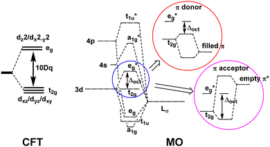
Ligand field theory (LFT) is one of the most enduring conceptual models in inorganic chemistry and remains a mainstay of the transition metal chemistry curriculum.1 It emerged in the 1950s in response to the quantitative failure of the earlier electrostatic crystal field theory (CFT).2In CFT, the d-orbital splitting in, for example, an octahedral crystal field of six point charges is 10Dq:
 | (1) |
Attempts to compute 10Dq from first principles gave poor agreement with experiment.3 In response, explicit calculation of the d-orbital splitting was replaced by a parametric fit to experimental data and 10Dq became the now familiar ligand field parameter Δoct.4
LFT combined the excellent symmetry treatment of CFT with the flexibility of a parametric approach and reproduced the d–d spectra and magnetic properties of dn Werner-type complexes to good accuracy.5 LFT was very successful and many ligand field concepts, such as the spectrochemical series, and the ligand field stabilisation energy (LFSE), entered mainstream chemical nomenclature. However, the global, symmetry-based parameters such as Δoct were unsatisfactory. In particular, they failed to account for how a negatively charged ligand such as fluoride could have a much smaller ligand field than neutral ligands such as ammonia or a phosphine. Mulliken's MO model suggested a resolution.
The qualitative MO diagram for σ-only ligands identifies Δoct as the splitting between the σ-antibonding  MOs, which are mostly metal d, and the non-bonding t2g orbitals, which are 100% metal (Fig. 1, middle). By adding specific M–L π interactions – i.e. only the t2g sets – the (partial) MO picture shows how Δoct becomes a competition between σ bonding and π bonding (Fig. 1, right). For π donors like F− with filled, low-energy π levels, the mostly-d
  orbitals are destabilised, which reduces Δoct, while for π acceptor ligands, such as phosphines or CO which have empty, high-energy π orbitals, the mostly-d t2g orbitals are stabilised, which tends to increase Δoct. LFT was widely viewed as an application of the MO model.5
However, in the early 1980s, a contrary view was put forward by Gerloch and Woolley (GW).6–9 They formulated LFT as a projection operator approach based on the density functional theorem. The only explicit orbitals in this formulation are the metal d orbitals and all the M–L bonding interactions are implicitly accounted for in the d-orbital sequence and relative energies. These are functions of the one-electron, ligand field bonding parameters.
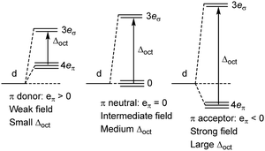
The most successful parameterisation schemes are the angular overlap model (AOM)10 and the cellular ligand field (CLF) approach6,9,11 both of which assign local σ and π bonding parameters to model each M–L interaction implicitly. For example, the d-orbital splitting in Oh systems, Δoct, is, in both AOM and CLF schemes, given by:
| Δoct = 3eσ − 4eπ | (2) |
In the MO model, the metal d orbitals explicitly overlap with appropriate symmetry-adapted ligand orbitals forming bonding and anti-bonding sets. Orbital overlap/mixing is the only mechanism available to alter orbital energies. At the weak-overlap extreme, the bonding set is mostly ligand while the antibonding set is mostly metal d. The latter are thus associated with the conventional ‘ligand field’ (Fig. 2, left). As the ligand orbitals rise relative to the metal orbitals and the covalent mixing increases, the ligand frontier orbitals eventually become higher than the metal d. The M–L interaction is now ‘ultra-covalent’ – i.e. the bonding set is mostly d while the anti-bonding set is now mostly ligand. In the octahedral model complex, the mostly-d eg orbitals are now below the mostly-d t2g orbitals implying Δoct is negative (Fig. 2, right). The ligand field is apparently ‘inverted’.12
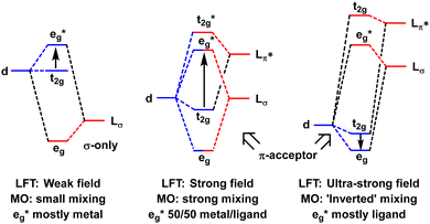 | ||
| Fig. 2 Schematic depiction of the effect of progressively increasing the energies of the ligand orbitals relative to the metal d orbitals. | ||
Based on MO calculations, an inverted ligand field has been proposed for planar [Cu(CF3)4]− (Fig. 3).12,13 The mostly-d b1g(dx2−y2) orbital is proposed to be bonding and thus filled suggesting that a ‘reduced’ d10 CuI formulation with three CF3− and one oxidised CF3+ ligands is more appropriate than a low-spin d8 CuIII configuration with four CF3− ligands.
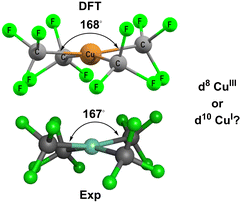 | ||
| Fig. 3 Structure of [Cu(CF3)4]−. Top: DFT-optimised. Bottom: Experimental.14 See ESI† for further details. | ||
Of course, this analysis is model dependent and relies on the overlap mechanism inherent in MO theory. In contrast, the only explicit orbitals in the GW formulation of LFT are the metal d functions and increasing covalency simply means increasing the ligand field from weak field to strong field (Fig. 4). Δoct gets larger but the d-orbital sequence is unaltered. The GW LFT ligand field for planar [Cu(CF3)4]− can never invert simply by increasing σ bonding. An alternative mechanism is required.
This paper reconciles the apparently disparate bonding pictures of MO theory and LFT by developing an equivalent ligand-field-based mechanism for internal electron transfer and exploring under what circumstances this mechanism applies. To achieve this, we address the issues of (i) what is meant by the term ‘ligand field picture’; (ii) does it apply to organometallics at all and (iii) if so, how far does it extend and what insights can LFT provide into the nature of metal–ligand bonding across the whole of transition metal chemistry.
2. Theoretical and computational details
2.1. Ligand field theory
The ligand field formalism described by Gerloch and Woolley7–9 is an example of a projection operator method. In general, each solution, Ei, of the exact Schrödinger equation, which uses the full Hamiltonian, , and a complete set of basis functions, {Φ}, can be projected onto an effective Hamiltonian,
  , with its co-defined basis set {ϕi} (eqn (3)). In principle, this procedure is exact. However, as implied by the nomenclature in eqn (3), the effective Hamiltonian and its basis set are energy dependent. Each energy state requires a different Hamiltonian/basis set combination, and the process has little value.
 | (3) |
The ligand field Hamiltonian,  , (eqn (4)) comprises just three terms: the ligand field potential, VLF, d–d interelectron repulsion, U(i,j) and spin–orbit coupling, l·s, acting on a basis set derived from the multiplet states arising from an ‘atom-like’ dn configuration. The two-electron inter-electron repulsion term and the relativistic spin–orbit coupling term can thus be handled within the central field – i.e. spherical – approximation used for isolated atoms and ions. The molecular symmetry is only incorporated into the one-electron, ligand field potential, VLF, and the M–L bonding interactions are captured implicitly in the sequence and energies of the d orbitals.
This form of LFT is thus a many-electron, relativistic treatment capable of making direct contact with experimental observables which are inherently many-electron quantities. It is thus quite different from the simple (and simplistic) qualitative molecular orbital (MO) picture often touted as ligand field theory. In this work, the label ‘LFT’ will not be applied to this MO version.
 | (4) |
2.2. Ab initio LFT
The aiLFT method15–18 is a correlated, multireference wavefunction method which encapsulates the central features of LFT but, in contrast to the parametric formulation, aiLFT is completely independent of experiment. It involves a complete active space self consistent field (CASSCF) calculation where the active space comprises the five mainly-d molecular orbitals (i.e. those with a total Löwdin d component greater than 50%) containing the n electrons of the formal dn metal configuration. The CASSCF treatment of static electron correlation is then augmented by an n-electron valence state perturbation theory (NEVPT2) treatment of dynamic correlation. The aiLFT approach generates the same number of states as that from the dn configuration and the wavefunction results can be directly mapped onto an equivalent LFT description. A fitting procedure then extracts the underlying ligand field d orbital energies and Racah interelectron repulsion parameter values of the aiLFT Hamiltonian. Subsequent fitting of the aiLFT d orbital energies using a conventional AOM/CLF analysis affords eλ parameter values which can be used to interpret the local M–L chemical bonding.For example, the d2 configuration is 45-fold degenerate and, within the Russell–Saunders coupling scheme, generates five many-electron terms, 3F, 3P, 1S, 1D and 1G which are 21, 9, 1, 5 and 9-fold degenerate respectively. The energies of these ‘free ion’ terms can be expressed in terms of electrostatic d–d interelectron repulsion parameters either using the original Condon–Shortley scheme (F0, F2 and F4) or the Racah scheme (A, B and C) (see ESI†). In the presence of a ligand field, the terms split. The term energies now have an additional dependence on the d-orbital separations. Thus, there are 10 spin triplets and 15 spin singlets for the state averaged CASSCF procedure to compute. The aiLFT procedure then determines the values of the Racah parameters and d orbital energies which deliver the best fit to the CASSCF results. The choice of active space and number of states guarantees that the active orbital populations for a given dn system are n/5 which maps on to the ligand field idea of an atom-like d configuration arising from the presumed dominant spherical contribution to the ligand field.
All the calculations employed the ORCA program system,19,20 version 4.2.1. All molecules were initially geometry-optimised using the BP86 functional with def2-SVP basis sets for all atoms bar the metal centre where a def2-TZVP basis is used. Grimme empirical dispersion corrections (keyword D3BJ) and a CPCM solvation field appropriate to ethanol or water were included. For paramagnetic systems, a spin-unrestricted approach was used. Cartesian coordinates for all the systems considered here and further details of the aiLFT protocol are included in the ESI.†
3. Results and discussion
An important characteristic of the ligand field approach, both parametric and ab initio, is the separation of the one-electron and two-electron contributions. The former generate a set of orbitals which provides a powerful insight into the nature of metal–ligand bonding. The developers of aiLFT demonstrated that it is able to ‘recover the ligand field picture from ai data’ and with an accuracy comparable to the conventional parametric approach.15 While neither framework is perfect, there are many useful empirical trends derived from parametric ligand field analysis and aiLFT appears to reproduce them faithfully. We will rely on this qualitative correspondence here and base our analysis exclusively on aiLFT results.3.1. Planar [Cu(CF3)4]− and related systems
[Cu(CF3)4]− has attracted a lot of experimental and theoretical interest, much of it centred on the formal oxidation state and d configuration of the metal centre.12–14,21–25 At first sight, this complex is a low-spin d8 CuIII system which is consistent with the nearly planar structure (Fig. 5, top). The slight D2d distortion (the large C–Cu–C angle is 168°) is due to steric interactions between the F atoms. Smaller CH3 ligands generate basically the same ligand field (vide infra) as CF3 but the geometry is now strictly planar (Fig. 5, middle). In contrast, an unambiguously d10 system such as the model compound [Zn(CF3)4]2− is tetrahedral (Fig. 5, bottom).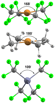 | ||
| Fig. 5 DFT-optimised structures for [Cu(CF3)4]− (top), [Cu(CH3)4]− (middle) and [Zn(CF3)4]2− (bottom). | ||
Of special interest here is the suggestion of a so-called ‘inverted ligand field’ for [Cu(CF3)4]−.12,13 As described in the introduction, an inverted ligand field is a feature of the MO model. For [Cu(CF3)4]−, the inversion results in the (mostly) σ-type d orbital (dxy in D2d symmetry) becoming bonding and thus filled. Compared to the Cu(III) d8 formulation, this inversion can be interpreted as tantamount to a two-electron reduction of the metal centre. However, this mechanism relies on the overlap between metal-centred and ligand-centred functions which is not possible in the d-orbital-only formulation of LFT.
The only explicit orbitals in LFT are the metal d functions and the d-orbital sequence can never be inverted simply by increasing the σ-bonding covalency. However, if there really is an internal electron transfer, the initially-assumed d configuration should no longer apply and the aiLFT calculation would be expected to fail.
The results of the aiLFT calculations for [Cu(CF3)4]− and [Cu(CH3)4]− are presented in Table 1. The active space orbitals are dominated by d contributions of 61% or more, the d orbital splitting is the 1![[thin space (1/6-em)]](https://www.rsc.org/images/entities/char_2009.gif) :
:![[thin space (1/6-em)]](https://www.rsc.org/images/entities/char_2009.gif) 4 pattern typical of planar complexes with the σ-bonding dxy much higher than the other four, and the Racah parameters are reasonable given that aiLFT tends to overestimate their magnitudes compared to empirical values obtained by fitting experimental d–d spectra.15,17 Overall, therefore, aiLFT supports the low-spin d8 CuIII formulation.
4 pattern typical of planar complexes with the σ-bonding dxy much higher than the other four, and the Racah parameters are reasonable given that aiLFT tends to overestimate their magnitudes compared to empirical values obtained by fitting experimental d–d spectra.15,17 Overall, therefore, aiLFT supports the low-spin d8 CuIII formulation.
| aiLFT data | [Cu(CF3)4]− | [Cu(CH3)4]− | ||||
|---|---|---|---|---|---|---|
| %d | ΔE(CAS) | ΔE(NEVPT2) | %d | ΔE(CAS) | ΔE(NEVPT2) | |
| dxy | 61 | 38![[thin space (1/6-em)]](https://www.rsc.org/images/entities/char_2009.gif) 617 617 |
65![[thin space (1/6-em)]](https://www.rsc.org/images/entities/char_2009.gif) 898 898 |
58 | 40![[thin space (1/6-em)]](https://www.rsc.org/images/entities/char_2009.gif) 830 830 |
72![[thin space (1/6-em)]](https://www.rsc.org/images/entities/char_2009.gif) 024 024 |
| dx2−y2 | 99 | 1985 | 0 | 98 | 3954 | 3033 |
| dz2 | 91 | 1121 | 1564 | 93 | 211 | 1481 |
| dxz | 93 | 2 | 1037 | 98 | 0 | 0 |
| dyz | 93 | 0 | 1032 | 98 | 0 | 0 |
| B | — | 1018 | 1249 | — | 1068 | 1262 |
| C | — | 5297 | 2962 | — | 5506 | 3012 |
The CLF bonding parameters for [Cu(CF3)4]−, and a series of related complexes, were derived by fitting the aiLFT d orbital energies and are given in Table 2.26 These planar, or near planar, systems include contributions from the ‘coordination voids’ above and below the plane of the molecule as required by the CLF model.27–29 For the cyanide complexes, there are four parameters but only three degrees of freedom in D4h symmetry so the nominal values of eπ(void) have been chosen to correlate roughly with the magnitude of eσ(void). Both [CF3]− and [CH3]− are assumed to be σ-bonding-only although the author acknowledges that there is evidence that the aiLFT introduces a small π-bonding contribution in related M–NH3 interactions30 which, if repeated for alkyl ligands, would directly influence the eπ(void) parameter. However, the magnitudes of the eπ(NH3) parameters is of the order of 500 to 1000 cm−1 which would not be significant here.
| Complex | Symmetry | Level | e σ(eq) | e π(eq) | e σ(void) | e π(void) |
|---|---|---|---|---|---|---|
| a Assumed value. | ||||||
| [CuIII(CF3)4]− | D 2d | CAS | 12![[thin space (1/6-em)]](https://www.rsc.org/images/entities/char_2009.gif) 500 500 |
0a | −7000 | −1400 |
| NEVPT2 | 22![[thin space (1/6-em)]](https://www.rsc.org/images/entities/char_2009.gif) 450 450 |
0a | −9900 | −200 | ||
| [CuIII(CH3)4]− | D 4h | CAS | 12![[thin space (1/6-em)]](https://www.rsc.org/images/entities/char_2009.gif) 300 300 |
0a | −8150 | −1980 |
| NEVPT2 | 22![[thin space (1/6-em)]](https://www.rsc.org/images/entities/char_2009.gif) 997 997 |
0a | −12![[thin space (1/6-em)]](https://www.rsc.org/images/entities/char_2009.gif) 239 239 |
−1516 | ||
| [NiII(CF3)4]2− | D 2d | CAS | 7200 | 0a | −4700 | −1100 |
| [NiII(CN)4]2− | D 4h | CAS | 8400 | −400 | −5850 | −1200 |
| [CuIII(CN)4]− | D 4h | CAS | 11![[thin space (1/6-em)]](https://www.rsc.org/images/entities/char_2009.gif) 900 900 |
−400 | −9000 | −2000 |
Comparing the CuIII species at the CAS level, eσ(Leq) is ∼12![[thin space (1/6-em)]](https://www.rsc.org/images/entities/char_2009.gif) 000 ± 250 cm−1, eσ(void) is −8000 ± 1000 cm−1 and eπ(void) is ∼−1700 ± 300 cm−1. Thus, from an ab initio ligand field perspective, [CF3]−, [CH3]− and [CN]− generate similar, strong ligand fields, implying strong metal–ligand covalency, but that there is little distinction between a cyanide ‘coordination complex’ and a methyl or trifluoromethyl ‘organometallic compound’.
000 ± 250 cm−1, eσ(void) is −8000 ± 1000 cm−1 and eπ(void) is ∼−1700 ± 300 cm−1. Thus, from an ab initio ligand field perspective, [CF3]−, [CH3]− and [CN]− generate similar, strong ligand fields, implying strong metal–ligand covalency, but that there is little distinction between a cyanide ‘coordination complex’ and a methyl or trifluoromethyl ‘organometallic compound’.
The aiLFT results support a d8 Cu(III) formulation while the MO approach is more consistent with d10 Cu(I). However, both conclusions depend on the orbitals of the model and the aiLFT d orbitals are very different from the orbitals of MO theory. It should therefore come as no surprise that the two frameworks give different ‘answers’ which, at first sight, may appear to be at odds. Leach et al.22 attempt to bridge the two extremes by proposing a quasi-d10 formulation which allows for the effects of covalency to alter the actual d orbital populations while Alayoglu et al.21 propose further experimental support for the Cu(I) formulation. However, irrespective of the mechanisms permitted by our choices of model, whether theoretical12,22,31 or experimental, at the very least we can all agree that the Cu–C bonds in [Cu(CF3)4]− are very covalent.
3.2. [M(CO)6]m
The octahedral metal carbonyl compounds [Fe(CO)6]2+, [Mn(CO)6]+, Cr(CO)6, [V(CO)6]− and [Ti(CO)6]2− provide a further test of how much the ligand field regime overlaps what is conventionally considered as organometallic chemistry. The calculated results are given in see Table 3.| Compound | r(M–C) | R(C–O) | %d(t2g) | %d(eg) | Δ oct(CAS) | Δ oct(NEVPT2) |
|---|---|---|---|---|---|---|
| [Fe(CO)6]2+ | 1.876 | 1.134 | 94.4 | 85.4 | 30![[thin space (1/6-em)]](https://www.rsc.org/images/entities/char_2009.gif) 750 750 |
37![[thin space (1/6-em)]](https://www.rsc.org/images/entities/char_2009.gif) 900 900 |
| [Mn(CO)6]+ | 1.878 | 1.145 | 83.5 | 85.2 | 35![[thin space (1/6-em)]](https://www.rsc.org/images/entities/char_2009.gif) 670 670 |
48![[thin space (1/6-em)]](https://www.rsc.org/images/entities/char_2009.gif) 090 090 |
| Cr(CO)6 | 1.900 | 1.153 | 67.7 | 83.9 | 42![[thin space (1/6-em)]](https://www.rsc.org/images/entities/char_2009.gif) 000 000 |
60![[thin space (1/6-em)]](https://www.rsc.org/images/entities/char_2009.gif) 660 660 |
| [V(CO)6]− | 1.954 | 1.173 | 60–65 | * | * | * |
| [Ti(CO)6]2− | 2.043 | 1.189 | 51–58 | * | * | * |
All five species are formally 18-electron, low-spin d6 compounds. However, only [Fe(CO)6]2+, [Mn(CO)6]+ and Cr(CO)6 maintain the integrity of the d-orbital active space: [V(CO)6]− has one of the eg orbitals replaced by a mainly metal-s orbital while for [Ti(CO)6]2−, both metal eg orbitals have been swapped out for ligand-based functions.
Thus, the aiLFT protocol developed here has limits. Given that there is a smooth progression in the experimental C–O stretching mode energy from 2204 cm−1 for [Fe(CO)6]2+ through to 1750 cm−1 for [Ti(CO)6]2−, this seems to be more an issue with aiLFT rather than any fundamental change in the nature of the bonding. Nevertheless, any derived parameters from ‘failed’ aiLFT calculations need to be treated with extreme caution.
For [Fe(CO)6]2+, [Mn(CO)6]+ and Cr(CO)6 where the aiLFT protocol gives acceptable results, separate eσ and eπ parameters can be extracted by applying a small trigonal elongation of ∼3° which splits the nominal t2g dπ orbitals (Fig. 6, left). The sense of the dπ orbital splitting, ΔE1, determines sign of eπ (Fig. 6, right).
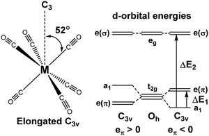 | ||
| Fig. 6 Trigonal distortion applied to M(CO)6 compounds and relationship between the sense of splitting of the t2g orbitals and the sign of the eπ parameter. | ||
The ligand field bonding picture (see Table 4) has carbonyl acting as a good σ donor and progressively stronger π acceptor for Fe to Cr. There is a suggestion that π acceptance saturates as the metal oxidation state approaches zero although the estimate of eπ is very sensitive to the ΔE1 value. The ligand field bonding picture in these metal carbonyl species, derived exclusively from considering just the d orbitals, is thus in agreement with conclusions based on MO treatments.32
3.3. Metallocenes and ηn-bonded ligands
Metallocenes are the ‘poster children’ for organometallic chemistry but are nevertheless generally well-treated by LFT.33 Historically, this relied on the correct identification of experimental spectroscopic data which, even for the archetype ferrocene, is an issue.34 However, given reliable data, the electronic structures of metallocenes are well-reproduced by ligand field calculations. However, as for the octahedral M(CO)6 systems mentioned above, the high symmetry makes the CLF analysis of the bonding picture ambiguous.In LFT, M(Cp)2 compounds are modelled as linear ML2 systems with effective D∞h/C∞v symmetry. The d orbitals split into a 1![[thin space (1/6-em)]](https://www.rsc.org/images/entities/char_2009.gif) :
:![[thin space (1/6-em)]](https://www.rsc.org/images/entities/char_2009.gif) 2
2![[thin space (1/6-em)]](https://www.rsc.org/images/entities/char_2009.gif) :
:![[thin space (1/6-em)]](https://www.rsc.org/images/entities/char_2009.gif) 2 pattern with a clean symmetry separation of dσ(dz2)
2 pattern with a clean symmetry separation of dσ(dz2)![[thin space (1/6-em)]](https://www.rsc.org/images/entities/char_2009.gif) :
:![[thin space (1/6-em)]](https://www.rsc.org/images/entities/char_2009.gif) dπ(dxz/dyz)
dπ(dxz/dyz)![[thin space (1/6-em)]](https://www.rsc.org/images/entities/char_2009.gif) :
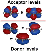
:![[thin space (1/6-em)]](https://www.rsc.org/images/entities/char_2009.gif) dδ(dxy/dx2−y2). There are two degrees of freedom in this model. However, the Cp− ligand has six valence electrons in five π-type orbitals and, with respect to the Cp–M interaction, there are one σ donor, two π donor and two δ acceptor orbitals (Fig. 7). This requires three CLF parameters: eσ and eπ which should be positive and eδ which should be negative.
dδ(dxy/dx2−y2). There are two degrees of freedom in this model. However, the Cp− ligand has six valence electrons in five π-type orbitals and, with respect to the Cp–M interaction, there are one σ donor, two π donor and two δ acceptor orbitals (Fig. 7). This requires three CLF parameters: eσ and eπ which should be positive and eδ which should be negative.
The geometry of metallocenes, and indeed other homoleptic sandwich compounds, places the ligand bonding electron density close to the nodal surface of the metal dz2 orbital. Hence, the σ interaction is expected to be relatively minor and eσ should be small. In contrast, M–L π bonding is strong and eπ should be large and positive. The significance of M–L δ-backbonding varies with the ligand.
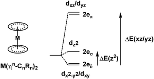
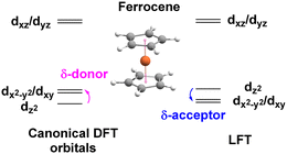
The ligand field analysis for a general, linear M(ηn-L)2 system (Fig. 8) gives eσ − eδ = ½[ΔE(z2)] where ΔE(z2) = E(dz2) − E(dxy). For Fe(Cp)2, aiLFT gives ΔE(z2) at ∼3000 cm−1 at the CASSCF level (Table 5). Thus, if σ-bonding is presumed to be minor – eσ(Cp) is, say, ∼500 to 1000 cm−1 – then so too is the Fe–Cp δ interaction (eδ ∼ −1000 to −500 cm−1) and the Fe–Cp π bond is dominant (eπ ∼ 10![[thin space (1/6-em)]](https://www.rsc.org/images/entities/char_2009.gif) 000 cm−1). It should be noted that the sense of the dz2/(dx2−y2,dxy) splitting determines whether the Cp− ligand is a δ-donor (dz2 < dx2−y2/dxy) or a δ-acceptor (Fig. 9). Canonical DFT orbitals give a ‘ligand field’ with dz2 lower than dx2−y2/dxy thus suggesting Cp− is a δ-donor.34 In contrast, the CLF analysis, the empty acceptor δ orbitals on the Cp− pro-ligand, the filled δ donor orbitals on the Fe centre and a DFT-based energy decomposition analysis (EDA) (vide infra) all support Cp− being a δ-acceptor.35 Great care should be taken in interpreting the relationship between canonical orbitals and the nature of M–L bonding.36
000 cm−1). It should be noted that the sense of the dz2/(dx2−y2,dxy) splitting determines whether the Cp− ligand is a δ-donor (dz2 < dx2−y2/dxy) or a δ-acceptor (Fig. 9). Canonical DFT orbitals give a ‘ligand field’ with dz2 lower than dx2−y2/dxy thus suggesting Cp− is a δ-donor.34 In contrast, the CLF analysis, the empty acceptor δ orbitals on the Cp− pro-ligand, the filled δ donor orbitals on the Fe centre and a DFT-based energy decomposition analysis (EDA) (vide infra) all support Cp− being a δ-acceptor.35 Great care should be taken in interpreting the relationship between canonical orbitals and the nature of M–L bonding.36
There is no ambiguity for Cr(C6H6)2. Both canonical DFT and aiLFT place dz2 substantially above the dδ orbitals and benzene is thus a much stronger δ acceptor than Cp−. The aiLFT energy difference ΔE(z2) in Cr(C6H6)2 is ∼20![[thin space (1/6-em)]](https://www.rsc.org/images/entities/char_2009.gif) 000 cm−1 so that if eσ is still presumed to relatively small, eδ(C6H6) is substantial (∼−10
000 cm−1 so that if eσ is still presumed to relatively small, eδ(C6H6) is substantial (∼−10![[thin space (1/6-em)]](https://www.rsc.org/images/entities/char_2009.gif) 000 cm−1) with eπ being of comparable magnitude, although the latter varies quite steeply as a function of eσ. Qualitatively, therefore, ligand field analysis of the aiLFT d orbital energies suggests that the Cp− ligands in Fe(Cp)2 are strong π donors, but relatively weak σ donors and weak δ acceptors, while the C6H6 ligands in Cr(C6H6)2 are weak σ donors but strong π donors and strong δ acceptors. In both cases, the dπ orbitals are the most destabilised.
000 cm−1) with eπ being of comparable magnitude, although the latter varies quite steeply as a function of eσ. Qualitatively, therefore, ligand field analysis of the aiLFT d orbital energies suggests that the Cp− ligands in Fe(Cp)2 are strong π donors, but relatively weak σ donors and weak δ acceptors, while the C6H6 ligands in Cr(C6H6)2 are weak σ donors but strong π donors and strong δ acceptors. In both cases, the dπ orbitals are the most destabilised.
This ligand field picture compares quite well to the DFT-based EDA analysis of Rayon and Frenking.35 They too conclude that Fe(Cp)2 is dominated by Fe–Cp π bonding but suggest that δ dominates π bonding in Cr(C6H6)2. The ligand field picture has much more equal π and δ contributions. The difference can probably be attributed to the metal reference states.
The ligand field reference state is spherically symmetric and the d orbitals are equally occupied: 1.2 per orbital for d6 systems. The state averaged CASSCF of aiLFT gives the same result. In contrast, the EDA analysis used a ‘prepared’ Cr atom with a dz22dxy2dx2−y22 configuration. Thus, the EDA analysis starts with four electrons in the metal δ orbitals while the LFT/aiLFT δ population for a d6 system is only 2.4 consistent with the EDA calculation favouring δ backbonding more than LFT. Nevertheless, it is encouraging to note that the bonding pictures derived from two quite different approaches, are broadly the same.
3.4. [Ni(Cp)2]2+: the aiLFT protocol fails
The recently-reported [Ni(Cp)2]2+ species provides further insights into the aiLFT protocol in particular and LFT in general. Formally, this is a d6 Ni(IV) compound which is the highest reported oxidation state for Ni.37 However, higher oxidation states require hard, electronegative donors like F− so strongly covalent ligands like Cp− should not be able to support a formal +4 charge on the metal centre. The authors go further and suggest, based on an atoms-in-molecule atomic charge analysis, that the actual metal charges in [NiII(Cp)2], [NiIII(Cp)2]+ and [NiIV(Cp)2]2+ are all about the same and that it is the Cp ligand charge which varies with the total charge.38If this is true, then the aiLFT assumption of a d6 configuration for [Ni(Cp)2]2+ should not be valid. In agreement with this suggestion, the aiLFT calculation fails (Table 6). This result is not an artefact, since aiLFT calculations for 20-electron, high-spin d8 [NiII(Cp)2] and 18-electron, low-spin d6 [NiIVF6]2− maintain the integrity of the presumed d configuration (Table 6). This behaviour simply reflects that there are ligand- and geometry-dependent limits on the maximum formal oxidation state the metal can achieve. This is a well-known phenomenon illustrated, for example, by the so-called ‘oxo-wall’ for tetragonal first-row metal-oxo complexes.39
| aiLFT data | Ni(Cp)2 | [Ni(Cp)2]2+ | [NiF6]2− | ||||||
|---|---|---|---|---|---|---|---|---|---|
| %d | ΔE(CAS) | ΔE(NEVPT2) | %d | ΔE(CAS) | ΔE(NEVPT2) | %d | ΔE(CAS)a | ΔE(NEVPT2)a | |
| a Minor deviations from rigorous Oh symmetry due to small amount of ‘noise’ from the solvent field. | |||||||||
| dxy | 99 | 0 | 0 | 8 | 1347 | 1321 | 90 | 3 | 20 |
| dx2−y2 | 99 | 0 | 0 | 89 | 7588 | 85![[thin space (1/6-em)]](https://www.rsc.org/images/entities/char_2009.gif) 186 186 |
67 | 20![[thin space (1/6-em)]](https://www.rsc.org/images/entities/char_2009.gif) 857 857 |
28![[thin space (1/6-em)]](https://www.rsc.org/images/entities/char_2009.gif) 128 128 |
| dz2 | 98 | 1244 | 1037 | 95 | 0 | 0 | 67 | 20![[thin space (1/6-em)]](https://www.rsc.org/images/entities/char_2009.gif) 852 852 |
28![[thin space (1/6-em)]](https://www.rsc.org/images/entities/char_2009.gif) 100 100 |
| dxz | 88 | 11![[thin space (1/6-em)]](https://www.rsc.org/images/entities/char_2009.gif) 372 372 |
17![[thin space (1/6-em)]](https://www.rsc.org/images/entities/char_2009.gif) 541 541 |
28 | 33453 | 92![[thin space (1/6-em)]](https://www.rsc.org/images/entities/char_2009.gif) 062 062 |
90 | 0 | 0 |
| dyz | 88 | 11![[thin space (1/6-em)]](https://www.rsc.org/images/entities/char_2009.gif) 372 372 |
17![[thin space (1/6-em)]](https://www.rsc.org/images/entities/char_2009.gif) 541 541 |
33 | 30![[thin space (1/6-em)]](https://www.rsc.org/images/entities/char_2009.gif) 356 356 |
90![[thin space (1/6-em)]](https://www.rsc.org/images/entities/char_2009.gif) 454 454 |
90 | 1 | 15 |
| B | — | 1195 | 1136 | — | −937 | 1261 | — | 977 | 1083 |
| C | — | 4448 | 3727 | — | 10![[thin space (1/6-em)]](https://www.rsc.org/images/entities/char_2009.gif) 634 634 |
−9883 | — | 4561 | 2789 |
3.5. Pauli shields and the ligand field and ultra-covalent regimes
The numerical success of ligand field theory is due to the special nature of the ‘inner’ (n − 1)d orbitals which are shielded from strong covalent overlap with ligand orbitals by the Pauli repulsion arising from the semi-core, (n − 1)s and (n − 1)p metal orbitals (Fig. 10).40,41 This is particularly marked for 3d systems where the valence d orbitals have no radial node. The 3s and 3p orbitals are of comparable size to the 3d, but completely filled, which generates a ‘Pauli shield’ that leads to ‘stretched’ metal–ligand bonds. The ligand-field d orbitals are thus ‘atom-like’ and the central-field approximations used for d–d inter-electron repulsion and spin–orbit coupling are reasonably accurate. Systems where the Pauli shield ensures the integrity of the dn configuration are deemed to be in the ‘ligand field regime’ as depicted in Fig. 11, left.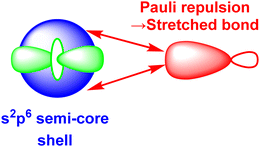 | ||
| Fig. 10 Schematic representation of the origins of the ‘Pauli shield’. (After Fig. 3 of ref. 41.) The (n − 1)s, (n − 1)p and (n − 1)d orbitals on the metal have comparable radii and the red double-headed arrows indicate the Pauli repulsion from the electrons in the filled s and p semi-core orbitals on the electron pair in the ligand σ bond (red). | ||
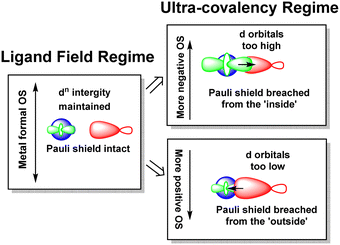 | ||
| Fig. 11 Schematic depiction of the ligand field regime, where the dn integrity is maintained, and the two scenarios in which this integrity is lost and the Pauli shield is breached. | ||
The ligand field analyses presented above suggest two mechanisms by which this Pauli shield might be breached. The M(CO)6 series conjures a picture of the metal being ‘overwhelmed’ as its formal oxidation state becomes more and more negative. The metal becomes so electron rich, and the π back-donation so strong, that metal d electrons overcome the Pauli shield from the ‘inside’ and ‘flood’ out into the ligand region as depicted schematically in Fig. 11, top right. Alternatively, and as exemplified by the behaviour of [Ni(Cp)2]2+, when the metal oxidation state becomes too positive, the d orbitals are dragged down so far that the Pauli shield is breached from the ‘outside’ and any empty metal d orbitals become filled by bonding electron density (Fig. 11, bottom right). This internal electron transfer is basically the same mechanism as the inverted ligand field of MO theory. In either event, the extreme ‘ultra-covalency’ destroys the integrity of the assumed aiLFT d configuration as well as the formal oxidation state.
Evidence for an imminent Pauli shield breach from the inside can be found in the aiLFT calculations for the metal hexacarbonyl series. The t2g/eg percentage compositions of the active orbitals for [FeII(CO)6]2+, [MnI(CO)6]+ and Cr0(CO)6 are 94/85, 84/85 and 66/84 respectively. The d component of the t2g orbitals drops progressively while the composition of the σ-type eg orbitals remains virtually constant. This correlates with only the t2g orbitals being occupied and hence solely responsible for any ‘internal’ Pauli shield breach. We should note also that at 61%, the dxy component of the Cu–C σ orbital in the active space of [Cu(CF3)4]− also suggests a system close to a Pauli shield breach.
The sandwich compounds illustrate a number of interesting features culminating in a Pauli shield breach from the outside for [Ni(Cp)2]2+ (Fig. 12). In common with octahedral VII complexes, V(Cp)2 has three low-energy d orbitals of similar energies and is therefore a high spin d3 system although the overall d orbital splitting is larger than the spin-pairing energy. The ligand field in Fe(Cp)2 is even stronger and with the higher d electron count, multiple spin states are possible with the low-spin d6 configuration favoured. However, the low-energy d orbitals must be above the bonding level threshold (the red dashed line in Fig. 12) since the oxidised low-spin d5 ferrocenium cation is paramagnetic but stable: that is, the ‘hole’ is not immediately swamped by bonding electron density. Ferrocene thus has a lot in common with ferrocyanide.
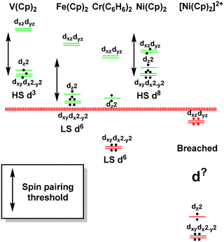 | ||
| Fig. 12 Schematic representation of the d orbital energies relative to the bonding level threshold (red dotted line) for a selection of organometallic sandwich compounds. | ||
The total ligand field splitting of Cr(C6H6)2 is almost twice that of Fe(Cp)2 which could mean that the lower d orbitals on chromium lie below the bonding threshold as depicted in Fig. 12. However, since they are already full, there are no internal electron transfer consequences. On the other hand, the strong stereochemical activity of the electrons in the strongly anti-bonding dπ orbitals of high-spin d8 Ni(Cp)2 lengthens the Ni–C distances by about 0.2 Å compared to the Fe–C distances in ferrocene and reduces the total ligand field splitting by about half. Ni(Cp)2 is therefore a weak field compound, the d8 configuration is well protected by the Pauli shield and the d orbitals are above the bonding threshold. However, the removal of the two dπ electrons to generate [Ni(Cp)2]2+ results in a dramatic shortening of the Ni–C distances and a sharp increase in Ni–Cp covalency which has a catastrophic effect on the d orbital energies. These descend well below the bonding threshold, the Pauli shield is breached from the outside, and the d6 configuration loses its integrity.
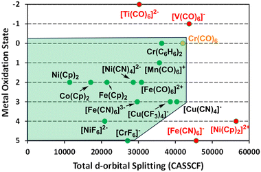
Clearly, the aiLFT calculations correlate strongly with both the strength of ligand field and the formal metal oxidation state. Using the compounds already analysed and some additional species, the limits of this ab initio ligand field envelope are displayed in Fig. 13. Significantly, within the bounds of where the ligand field/metal oxidation state combinations retain the d configuration integrity, the ab initio ligand field picture applies equally to ‘ionic’ Werner-type coordination complexes species and ‘covalent’ organometallic compounds. Hence, for all these systems, the same conceptual picture applies and the nature of the metal–ligand bonding can be inferred by analysing just the ligand field d orbitals.
3.6. The ligand field picture and valence electron counts
The ligand field picture involves the projection of the M–L bonding interactions onto the metal d orbitals and thus, the d orbitals are the only explicit functions we need to consider. The bonding electrons are implicit in the CLF parameters. Each positive eλ parameter represents an individual ligand–metal donor interaction of λ symmetry and involves a pair of electrons. Negative eλ parameters represent individual ligand–metal acceptor interactions of λ symmetry which affect the relevant d orbital energies but make no contribution to the valence electron count. For example, a CO ligand has a positive eσ and a negative eπ and is a two-electron donor while Cp− and C6H6 have a positive eσ, a positive eπ (i.e. eπx = eπy) and a negative eδ (i.e. eδxy = eδx2−y2) and are six-electron donors. (F− is formally an 8-electron donor but this issue will be dealt with in a future publication.)The electron count on the metal depends on its formal oxidation state. All the electrons are placed in its d orbitals. Thus, the CLF scheme for Cr(CO)6 comprises six positive eσ(CO) and six negative eπ(CO) giving 12 bonding electrons plus six electrons from the Cr0 centre: 18-electrons in total.
To account for the ligand field analyses discussed above, a Pauli shield was invoked to ‘protect’ the d orbitals from the bonding electrons. If the d orbitals get too low, as can occur for strongly-covalent and ultra-covalent systems, the Pauli shield can be breached. However, if these low-energy d orbitals are already filled, internal electron transfer is prevented and there are no significant consequences. The optimal d-electron counts thus correspond to filling up any low-lying d orbitals.
The binary metal carbonyls provide an good illustration and the CLF d-orbital energy level diagrams for four-, five- and six-coordinate compounds are shown schematically in Fig. 14 assuming eπ = −1/2eσ for illustrative purposes. For each symmetry, the σ-only bonding pattern is on the left and this connects to the pattern on the right which includes the effects of M–L π acceptance and the depression of the dz2 orbital in square pyramidal and square planar symmetry due to d–s mixing.42–44
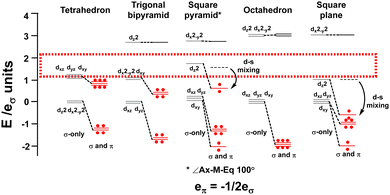 | ||
| Fig. 14 Optimal metal d electron counts (red dots) relate to d orbital splittings for strongly covalent M(CO)6 systems where the bonding threshold (dotted rectangle) is high. | ||
Fig. 14 emphasises that the key feature is the number of strongly destabilised d orbitals which are above the bonding threshold. For a threshold energy equivalent to about 2eσ, tetrahedral symmetry has no high-energy d orbitals, trigonal bipyramidal, square pyramidal and square planar compounds have one and octahedral symmetry has two. The optimal d electron counts are respectively 10, 8, 8, 8 and 6, and the bonding electron counts are 8, 10, 10, 8 and 12 giving total valence electron counts of 18, 18, 18, 16 and 18.
Note that these electron counts and, by association, the ‘18-electron rule’, depend on the magnitude of the ligand field. As shown in Fig. 9, for Fe(Cp)2 there are three low-energy d orbitals and an electron count of 18 but since the ligand field from Cp− is relatively weak, this is fortuitous. Neutral metallocenes behave like other coordination complexes of divalent metals and can support multiple electron counts. For example, vanadocene, like [V(OH2)6]2+, is only a 15-electron species while nickelocene, like [Ni(NH3)6]2+ is a 20-electron species. Moreover, the 17 electron ferrocenium cation is perfectly stable. If the ligand field is sufficiently low that the Pauli shield remains intact, the 18-electron rule need not apply.
3.7. Transition metal chemistry: κ- and η-bonded ligands
An important aspect of this work is the identification, in ligand field terms, of the M–L bonding features common to transition metal compounds. On the one hand, there are compounds where the ligands are κ-type and the σ-donor interaction is usually dominant (eσ ≫ eπ). This covers all of coordination chemistry and a significant number of organometallic compounds. On the other hand, there are the ηn-type systems where π-donation is usually dominant (eπ ≫ eσ). For cyclic ηn ligands, where n > 3, there is also the possibility of additional δ interactions. Haptic bonding is the exclusive domain of organometallic chemistry yet, significantly, the ligand field picture applies equally well to ferrocene as it does to ferrocyanide. This relatively simple conceptual framework thus puts all transition metal molecules on the same footing.4. Conclusions
The ligand field bonding picture formulated by Gerloch and Woolley treats the metal–ligand interactions implicitly via local σ, π and δ parameters. Their various effects are then reflected in the sequence and energy separations of the ligand field d orbitals. These are the only explicit orbitals in the model.Ligand-field analysis is well established in coordination chemistry and many features of metal complexes can be rationalised based solely on the metal d orbitals. However, the dearth of suitable ‘ligand-field’ experimental data for organometallic compounds makes it difficult, or impossible, to assess whether the ligand field picture even applies. In this paper, ab initio LFT has been employed as an experimental surrogate to explore the ligand field envelope computationally to try and establish the extent of the ligand field regime.
Calculated aiLFT d-orbital energies have been analysed within the CLF framework. Three types of compound have been considered: (i) the formally low-spin d8 complex [CuIII(CF3)4]−; (ii) the low-spin d6 hexacarbonyls [FeII(CO)6]2+, [MnI(CO)6]+, [Cr0(CO)6], [V−I(CO)6]− and [Ti−II(CO)6]2−; and (iii) the sandwich compounds d6 [FeII(Cp)2], d8 [NiII(Cp)2], d6 [NiIV(Cp)2]2+ and d6 Cr(C6H6)2. The first two groups are κ-bonded systems requiring only σ and π bonding parameters with σ-donor interactions dominant. The ηn-bonded cyclic ligands have significant M–L π-donor bonding with an additional δ-acceptor component.
The aiLFT protocol shows that the ligand fields of CO, Cp−, C6H6, [CF3]− and [CH3]− are comparable to that of cyanide and the formal oxidation states and d configurations for most of the complexes of these ligands are retained. Ligand field analyses of the aiLFT d orbital energies suggest that CO is a strong σ donor and, as the metal oxidation state becomes less positive, a progressively stronger π acceptor. Cp− is a good π donor, a weak σ donor and a relatively poor δ acceptor. C6H6 is also a good π donor and weak σ donor but is a much better δ acceptor than Cp−. Thus, both organometallic and coordination compounds falls within the ab initio ligand field envelope. However, there are limits on the oxidation state/ligand combination and the aiLFT protocol fails for [V(CO)6]−, [Ti(CO)6]2− and [Ni(Cp)2]2+.
For [V(CO)6]− and [Ti(CO)6]2− the oxidation state is too negative and the 3s23p6 ‘Pauli shield’ is breached from the inside. For [Ni(Cp)2]2+, the oxidation state is too positive and the aiLFT protocol fails because the Pauli shield is breached from the outside.
A visual representation of the boundary between the ligand field regime and the ultra-covalent regime is based on the total aiLFT d orbital splitting and the formal metal oxidation state. For M0 to MIII, the CASSCF limit is about 42![[thin space (1/6-em)]](https://www.rsc.org/images/entities/char_2009.gif) 000 cm−1 and all the ligands considered here give complexes within the ligand field envelope (Fig. 13). This includes [Cu(CF3)4]− which, according to the aiLFT protocol developed here, should be formulated as a low-spin d8 CuIII species rather than a d10 CuI compound as suggested by invoking the MO concept of ‘inverted ligand fields’. In the d-orbital-only form of LFT, the ligand field can never ‘invert’ simply by increasing the σ bonding but, crucially, all methods, both theoretical and experimental, agree that the Cu–C bond is very covalent. How this covalency manifests is model dependent.
000 cm−1 and all the ligands considered here give complexes within the ligand field envelope (Fig. 13). This includes [Cu(CF3)4]− which, according to the aiLFT protocol developed here, should be formulated as a low-spin d8 CuIII species rather than a d10 CuI compound as suggested by invoking the MO concept of ‘inverted ligand fields’. In the d-orbital-only form of LFT, the ligand field can never ‘invert’ simply by increasing the σ bonding but, crucially, all methods, both theoretical and experimental, agree that the Cu–C bond is very covalent. How this covalency manifests is model dependent.
For the higher oxidation states MIV and MV, the Pauli threshold is progressively lowered and, as illustrated by [NiIVF6]2− and [CrVF6]−, only fluoride is electronegative enough to maintain the integrity of their d configurations. In contrast, the formal oxidation states for [NiIV(Cp)2]2+ and [FeV(CN)6]− are too high for the ligand sets and these species lie outside the ab initio ligand field envelope. Their presumed d configurations of d6 and d3 respectively are not maintained in the aiLFT protocol. This does not necessarily imply that the ligand field picture is failing, rather that the aiLFT methodology can no longer isolate the required d orbitals.
The aiLFT analyses also suggest a simple method for rationalising the electron counts of organometallic compounds. The ligand electron count is based on the CLF parameterisation, which depends on the ligand's electronic structure, while the optimal d-electron count is based on the d orbital splittings. In weak-to-relatively-strong fields, all the d orbitals are above the bonding level threshold and the d electron count can be variable. Thus, Cp− compounds display electron counts of 15 in V(Cp)2 to 20 in Ni(Cp)2. For stronger-field ligands like CO, only the highest-energy d orbitals are above the bonding threshold and the lower d orbitals are filled. This leads to optimal d-electron counts of 6 for Cr(CO)6, 8 for Fe(CO)5 and 10 for Ni(CO)4 and, since there is only one positive CLF and thus CO is a 2-electron donor, total electron counts of 18. For planar compounds, only dx2−y2 (assuming D4h symmetry) is above the bonding threshold giving four filled d orbitals and a total valence electron count of 16.
In conclusion, the aiLFT protocol developed here has established that, in addition to the coordination complexes for which it was originally intended, d-orbital-only LFT encompasses a substantial proportion of organometallic chemistry. The main difference is that κ-ligated coordination complexes only require σ and π bonding modes with σ-bonding usually dominant while ηn-ligated systems have dominant π-bonding and are also capable of δ interactions. It is also apparent that d-orbital-only LFT includes important electron correlation effects which simple MO theory does not. In the author's opinion, the LFT label should be reserved for the implicit bonding formalism which, incidentally, has an actual ligand field. This ligand field picture allows the nature of the local M–L σ, π and δ interactions to be extracted simply by analysing the sequence and relative energies of the ligand field d orbitals and the structures and bonding of molecular transition metal systems can be understood using the same conceptual footing. Both coordination and organometallic compounds appear to have much more in common than may have been recognised hitherto.
Data availability
The data supporting this article have been included as part of the ESI.† The code for all the quantum chemical calculations can be found on the ORCA Forum download page https://orcaforum.kofo.mpg.de/app.php/dlext/. ORCA version 4.2.1 was employed for this study.Conflicts of interest
There are no conflicts of interest to declare.Acknowledgements
There is no funding to report in this work. Thanks to Dr David Fox for many stimulating discussions.References
- M. T. Weller, T. I. Overton, J. P. Rourke and F. A. Armstrong, Inorganic Chemistry, Oxford University Press, Oxford, 6th edn, 2018 Search PubMed.
- H. A. Bethe, Ann. Phys., 1929, 395, 133–208 CrossRef.
- W. H. Kleiner, J. Chem. Phys., 1952, 20, 1784–1791 CrossRef CAS.
- J. S. Griffith and L. E. Orgel, Q. Rev., Chem. Soc., 1957, 11, 381–393 RSC.
- C. J. Ballhausen, Introduction to Ligand Field Theory, McGraw-Hill, New York, 1962 Search PubMed.
- M. Gerloch, J. H. Harding and R. G. Woolley, Struct. Bonding, 1981, 1–46 CAS.
- M. Gerloch and R. G. Woolley, J. Chem. Soc., Dalton Trans., 1981, 1714–1717 RSC.
- R. G. Woolley, Mol. Phys., 1981, 42, 703–720 CrossRef CAS.
- M. Gerloch and R. G. Woolley, Prog. Inorg. Chem., 1983, 31, 371–446 CrossRef.
- C. E. Schäffer and C. K. Jorgensen, Mol. Phys., 1965, 9, 401 CrossRef.
- R. J. Deeth and M. Gerloch, J. Chem. Soc., Dalton Trans., 1986, 1531–1534 RSC.
- R. Hoffmann, S. Alvarez, C. Mealli, A. Falceto, T. J. Cahill, T. Zeng and G. Manca, Chem. Rev., 2016, 116, 8173–8192 CrossRef CAS.
- J. P. Snyder, Angew. Chem., Int. Ed. Engl., 1995, 34, 80–81 CrossRef CAS.
- C. Gao, G. Macetti and J. Overgaard, Inorg. Chem., 2019, 58, 2133–2139 CrossRef CAS.
- M. Atanasov, D. Ganyushin, K. Sivalingam and F. Neese, in Molecular Electronic Structures of Transition Metal Complexes II, ed. D. M. P. Mingos, P. Day and J. P. Dahl, Springer Berlin Heidelberg, Berlin, Heidelberg, 2012, pp. 149–220 DOI:10.1007/430_2011_57.
- M. Atanasov, D. Aravena, E. Suturina, E. Bill, D. Maganas and F. Neese, Coord. Chem. Rev., 2015, 289, 177–214 CrossRef.
- S. K. Singh, J. Eng, M. Atanasov and F. Neese, Coord. Chem. Rev., 2017, 344, 2–25 CrossRef CAS.
- L. Lang, M. Atanasov and F. Neese, J. Phys. Chem. A, 2020, 124, 1025–1037 CrossRef CAS.
- F. Neese, Wiley Interdiscip. Rev.: Comput. Mol. Sci., 2018, 8, e1327 Search PubMed.
- F. Neese, Wiley Interdiscip. Rev.: Comput. Mol. Sci., 2012, 2, 73–78 CAS.
- P. Alayoglu, T. Chang, C. Yan, Y.-S. Chen and N. P. Mankad, Angew. Chem., Int. Ed., 2023, 62, e202313744 CrossRef CAS.
- I. F. Leach, R. W. A. Havenith and J. E. M. N. Klein, Eur. J. Inorg. Chem., 2022, e202200247 CrossRef CAS.
- B. L. Geoghegan, Y. Liu, S. Peredkov, S. Dechert, F. Meyer, S. DeBeer and G. E. Cutsail, J. Am. Chem. Soc., 2022, 144, 2520–2534 CrossRef CAS.
- M. Gimferrer, A. Aldossary, P. Salvador and M. Head-Gordon, J. Chem. Theory Comput., 2021, 18, 309–322 CrossRef.
- R. C. Walroth, J. T. Lukens, S. N. MacMillan, K. D. Finkelstein and K. M. Lancaster, J. Am. Chem. Soc., 2016, 138, 1922–1931 CrossRef CAS.
- The NEVPT2 results give the same trends.
- R. J. Deeth, Dalton Trans., 2020, 49, 9641–9650 RSC.
- R. J. Deeth and M. Gerloch, Inorg. Chem., 1984, 23, 3846–3853 CrossRef CAS.
- R. J. Deeth, Eur. J. Inorg. Chem., 2020, 1960–1963, DOI:10.1002/ejic.202000143.
- M. Buchhorn and V. Krewald, Dalton Trans., 2023, 52, 6685–6692 RSC.
- J. P. Snyder, Angew. Chem., Int. Ed. Engl., 1995, 34, 986–987 CrossRef CAS.
- H. B. Gray and N. A. Beach, J. Am. Chem. Soc., 1963, 85, 2922–2927 CrossRef CAS.
- A. B. P. Lever, Inorganic Electronic Spectroscopy, Elsevier, New York, 2nd edn, 1984 Search PubMed.
- G. Drabik, J. Szklarzewicz and M. Radoń, Phys. Chem. Chem. Phys., 2021, 23, 151–172 RSC.
- V. M. Rayón and G. Frenking, Organometallics, 2003, 22, 3304–3308 CrossRef.
- R. J. Deeth, Faraday Discuss., 2003, 124, 379–391 RSC.
- S. Riedel and M. Kaupp, Coord. Chem. Rev., 2009, 253, 606–624 CrossRef CAS.
- J. M. Rall, M. Lapersonne, M. Schorpp and I. Krossing, Angew. Chem., Int. Ed., 2023, 62, e202312374 CrossRef CAS.
- J. R. Winkler and H. B. Gray, in Molecular Electronic Structures of Transition Metal Complexes I, ed. D. M. P. Mingos, P. Day and J. P. Dahl, 2012, vol. 142, pp. 17–28 Search PubMed.
- M. A. Buijse and E. J. Baerends, J. Chem. Phys., 1990, 93, 4129–4141 CrossRef CAS.
- M. Kaupp, J. Comput. Chem., 2007, 28, 320–325 CrossRef CAS.
- D. W. Smith, Inorg. Chim. Acta, 1977, 22, 107 CrossRef CAS.
- M. J. Riley, Inorg. Chim. Acta, 1998, 268, 55–62 CrossRef CAS.
- R. J. Deeth and D. L. Foulis, Phys. Chem. Chem. Phys., 2002, 4, 4292–4297 RSC.
Footnote |
| † Electronic supplementary information (ESI) available: Details of the aiLFT protocol, Cartesian coordinates of all systems subjected to aiLFT analysis, and aiLFT and CLF data for selected ML4 systems. See DOI: https://doi.org/10.1039/d4cp00764f |
| This journal is © the Owner Societies 2024 |

