 Open Access Article
Chiral induction in substrate-supported self-assembled molecular networks under nanoconfinement conditions
Zeno
Tessari
 ,
Tamara
Rinkovec
 and
Steven
De Feyter
 *
*
Division of Molecular Imaging and Photonics, Department of Chemistry, KU Leuven, Celestijnenlaan 200 F, 3001 Leuven, Belgium. E-mail: steven.defeyter@kuleuven.be
First published on 11th January 2024
Abstract
Self-assembly on surfaces often produces chiral networks, even when starting from achiral building blocks. However, when achiral molecules are used to produce chiral networks, two possible enantiomorphs are created with equal probability, rendering therefore the overall surface achiral. This outcome can be changed by finding a way to promote the preferential formation of one of the two enantiomorphs. In this regard, the creation of nanoconfined space, which has been called molecular corral, having a chosen orientation with respect to the substrate symmetry has been demonstrated to be a valid way to obtain the preferential self-assembly of a network having a determined chirality. In this study we aim to further expand the understanding of the principles of such mechanism, in particular by looking at unexplored parameters that could have a role in the production of the observed bias. In this way a deeper comprehension of the mechanisms at the base of the chiral self-assembly could be obtained.
Introduction
Self-assembly is a powerful strategy that, starting from simpler building blocks, which come together autonomously, allows one to obtain highly complex structures. Self-assembled structures have found interesting applications.1,2 Ideally, a perfect design of the system would yield a targeted outcome with the desired properties. Currently, this is achievable only for simple and predictable cases, particularly at the macroscale.3,4 However, in the majority of situations where molecular self-assembly complexity is higher, a priori tunability often remains out of reach. To improve the capability of predicting the outcome of self-assembly and thus designing building blocks suitable to obtain the desired final structures, it is of paramount importance to understand every aspect of the process. This is the reason why self-assembly is still the object of exploration, even if its concept has been known for decades.Particularly interesting is the exploitation of two-dimensional (2D) self-assembly to obtain a homochiral surface coverage, since in this way symmetry breaking can be obtained with little to no effort. This is highly interesting since chiral substrates have a central role in heterogeneous catalysis5–7 and in chiral separation.8,9 Chirality in 2D self-assembled molecular networks (SAMNs) is frequently observed since the reduced dimensionality of the system increases the possibility for symmetry breaking. Furthermore, when adsorbed on surfaces not only chiral molecules can adopt one of the five possible chiral plane symmetry groups, but also prochiral10 and achiral11 molecules can yield a chiral self-assembled 2D structure.12–17 Even if chirality appears in both situations, there is a difference between surfaces covered by SAMNs produced by chiral molecules and the ones covered by SAMNs formed by achiral molecules: in the former case, surfaces maintain chirality overall, while in the latter, surfaces show chirality only locally, remaining overall achiral.18 In fact, in case of achiral molecules, two SAMNs that are the mirror images of one another are possible (these structures are known as enantiomorphs) and such structures have identical probability of formation, thus covering the whole surface in equal proportions. However, there is the possibility to introduce an external bias to favor the formation of one of the two structures; this is called chiral induction. There are multiple strategies that can be utilized to induce global chirality in SAMNs formed by achiral material. The pioneering work of Green et al., who presented the sergeant-and-soldiers and the majority rule strategies,19,20 was translated also in two dimensions and applied to surfaces.21–24 In addition to those two possibilities, the use of chiral solvents can be a valid way to transfer the encoded chiral information that it contains to the SAMN formed by achiral building blocks.25,26 Inducing global chirality on surfaces does not have to pass from the addition of chiral materials; in fact, it is possible to use a properly oriented magnetic field, which, in combination with the substrate templating effect, could bias the production of one over two possible enantiomorphs.27,28
Another approach where instead of chiral material only the physical factors are used as a bias was recently developed in our group based on the use of the nanoshaving protocol.29,30 In particular, this strategy is based on the use of nanocontainers having a specific orientation with respect to the symmetry lattice of the graphite substrate. Such containers are used as a nanoconfinement environment where SAMNs can grow and, thanks to the specific orientation of these containers, a preferential structure is usually observed. Using this approach it was possible to preferentially form one out of two possible enantiomorphs starting from prochiral31 and achiral molecules.32 Furthermore, the same strategies have been proved effective in discriminating between enantiomers forming a racemic mixture, by adsorbing preferentially one of them inside these nanocontainers.33
Nanoshaving to produce nanocontainers, also referred to as nanocorrals, is particularly intriguing because it induces chirality by combining achiral elements. In fact, corrals are produced on a covalently functionalized piece of highly oriented pyrolytic graphite (HOPG) by using the metallic tip of a scanning tunneling microscope (STM) to remove, with nanometric control, covalently attached molecules, as shown in Fig. 1.29 In this area, the pristine HOPG substrate is restored and it becomes again available for self-assembly.29 This technique has been effective in determining the preferential formation of specific polymorphs34 or the formation of certain rotational domains,30 especially when performed in situ, i.e. in presence of the solution containing the molecules forming the SAMN studied. Part of the effectiveness of in situ nanoshaving has been attributed to a combination of kinetic effects, i.e. SAMNs nucleate and grow while the corral is in formation, and tip–molecules interactions during the nanoshaving.35
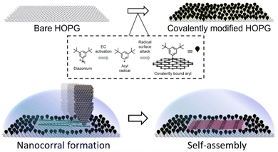 | ||
| Fig. 1 Schematic of the covalent HOPG modification, the nanoshaving process applied to create confined spaces, and the self-assembly in the nanocorrals. Top: the chemical modification process to modify HOPG involves the covalent attachment of aryl radicals using aryl diazonium salt as a precursor. Bottom: the use of a metallic STM tip to remove grafted molecules from a surface, creating a nanocorral, and facilitating self-assembly within the nanocorrals. Self-assembly may begin while the nanocorral is still being formed. Adapted with permission from ref. 30. Copyright 2016 American Chemical Society. | ||
In this work, we aim to further explore the impact of the kinetic contribution to the observed selection, obtained using corrals, by taking two alkoxylated isophthalic acid molecules, ISA-OC14 and ISA-OC22 (chemical structure in Fig. 3), having chains containing 14 and 22 carbon atoms, respectively. Because of this difference in length between the two molecules, the adsorption, nucleation and growth rate are expected to be different. By comparing the results obtained by studying the two SAMNs in corrals, we aim at gaining useful insights to understand the role of such parameters in the selection produced by corrals. Furthermore, the choice of these two alkoxylated isophthalic acid molecules is motivated by the previous successful investigation of ISA-OC18 in corrals.31
Experimental
Chemicals
ISA-OC14 was purified by recrystallization from methanol. The synthesis of ISA-OC22 has been previously reported.36 All other chemicals are commercially available and have been used without any further purification.Substrate preparation
All experiments were conducted on bare or modified HOPG. The grafting protocol used to modify HOPG is based on the electrochemical reduction of an in situ generated aryldiazonium salt. A 3 mM solution of 3,5-bis-tert-butylaniline was freshly prepared for each sample to be grafted, using as solvent 5 mL of an aqueous solution of HCl 50 mM. 100 μL of a 0.1 M aqueous NaNO2 solution was added to the aniline solution and the mixture was gently stirred and poured into the custom-made single-compartment electrochemical cell. After 2 minutes from the addition of the nitrile solution, a cyclic voltammetry program consisting of three cycles between 0.6 and −0.35 V with scan rate of 0.1 V was applied. When the program was finished, the HOPG sample was retrieved, rinsed with Milli-Q water a few times (Milli-Q, Millipore, 18.2 MΩ) and dried under a flux of Ar. In the electrochemical setup, the HOPG was mounted as working electrode, the counter electrode was a Pt wire, while the reference electrode used was based on the redox system Ag/AgCl/3 M NaCl. The potentiostat used to carry out the electrochemical measurements is an Autolab PGSTAT101 (Metrohm Autolab BV, The Netherlands).STM and nanoshaving
All STM measurements were performed on a PicoLE system (Keysight) at constant current mode operating at ambient conditions (room temperature between 20 and 24 °C) and using freshly cut tips from a Pt/Ir wire (80/20, 0.25 mm of diameter). One drop of ISA-OCn solution was dropcasted on the basal plane of freshly cleaved or modified HOPG substrate (grade ZYB, Advanced Ceramics Inc., Cleveland, Ohio, USA). The scanning parameters used for imaging are reported in the caption of the pictures, displayed as Vbias, for the bias applied between the tip and the sample, and as Iset, for the tunneling current set point. All the images were processed using Scanning Probe Imaging Processor software (SPIP version 6.5.1, Image Metrology ApS).Nanoshaving was performed always in situ, i.e., in the presence of the ISA-OCn-containing solution, using the PicoLITH software version 2.1 and setting the sample bias to −0.001 V and the current set point to 0.200 nA. The tip moving speed during the nanoshaving process was set to 0.4 μm s−1. All corrals were collected in different sessions; a new session starts whenever either the tip, the sample or both of them are changed. At the beginning of every session a few corrals were produced along a random orientation in order to understand the orientation of the substrate in the sample used. These initial corrals were discarded from analysis. Self-assembly in the corrals was probed by STM imaging immediately after their creation.
Results and discussion
ISA-OCn SAMNs and chiral confinement
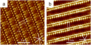
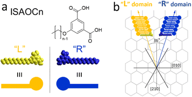
ISA-OC14 and ISA-OC22 (Fig. 2) organize both into a regular SAMN when adsorbed on HOPG. The SAMN has a high-density packing with ISA-OCn molecules arranged with the aromatic part interacting head-to-head (bright spots in the STM images), while the alkoxy chains are interdigitated forming a lamella. This lamellar structure is known and it has been reported36 to be analogous to the one formed by ISA-OC18.37–39 Both ISA-OC14 and ISA-OC22 adsorb on HOPG aligning their alkoxy chains along one of the main symmetry axes of graphite, i.e. the zigzag direction. The long axis of the lamellae that form the SAMNs is defined by the small unit cell vector a (0.97 ± 0.05 nm for ISA-OC14 and 0.96 ± 0.04 nm for ISA-OC22),36 and makes an off-set with a graphite's symmetry axis.ISA-OCn adsorbs with its phenyl group and alkoxy chain parallel to the surface. As it is a prochiral molecule, upon adsorption, a local 2D chiral situation is created. Depending on the face with which it adsorbs on the substrate, two possible chiral motifs are formed, referred to as “R” and “L”, as shown in Fig. 3a. Molecules adsorbed using the same face interact together creating, from the initial two possibilities, two different enantiomorphous SAMNs, which are the mirror image of one another. The two enantiomorphs consist of lamellar structures that tilt to the right or to the left with respect to a graphite's symmetry axis (armchair direction, e.g. [210]), as can be seen in Fig. 3b, depending if they are formed by “R” adsorbed ISA-OCn or by the “L” ones. Despite the alkoxy chains of the molecules forming the two enantiomorphs being aligned along the same main symmetry axis of HOPG, the lamellar axes in the two enantiomorphs form an angle of 36°, mirrored at the normal of one of the main symmetry directions of HOPG (e.g., [210]), as shown in Fig. 3b. Although there are only two enantiomorphs, the threefold symmetry of the HOPG lattice allows the formation of each of them along three equivalent directions. Therefore, on the HOPG substrate, six unique types of domains are formed that can be grouped in two sets; each set is formed by the three possible rotational structures of a certain enantiomorph. On the pristine HOPG, the three rotational domains forming a set are completely equivalent, since there is not a preferential direction. On the other hand, when considering the same rotational structures in corrals, it is possible to differentiate between them by taking the borders of the nanocontainer as a reference point.
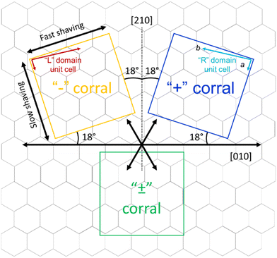
The goal of this study is to investigate the role of kinetic factors on the chiral selectivity observed for corrals. In order to do that, a method to impart chiral character to the corrals is required. Similarly to what was previously done for ISA-OC18,31 corrals were produced with a precise orientation with respect to the symmetry lattice of the substrate. In particular, starting from the top and bottom border aligned with one of the main symmetry axes of HOPG ([010] direction), two series of “chiral” corrals were produced, denoted as “+” and “−” corrals. The corrals were formed by rotating the top border 18° clockwise (“+”) or counterclockwise (“−”) with respect to the [010] direction of the substrate, as shown in Fig. 4. The direction of the top border is the direction along which the STM tip scans and is the same direction used as the fast nanoshaving axis. The lateral borders coincide with the slow nanoshaving direction. In particular, the lateral border of “+” corrals is intended to run parallel with unit cell vector a of “R” domains formed by ISA-OCn, while the lateral borders of “−” corrals are intended to align with the unit cell vector a of “L” domains formed by ISA-OCn. By carefully controlling the orientation of nanocorrals with respect to the symmetry lattice of the substrate, the area of HOPG exposed by corrals has a precise symmetry and this feature has been demonstrated useful in favoring the formation of structures having a precise chirality.31–33 Note though that the unit cell vector a of the targeted domain is not always perfectly parallel to the lateral side of the corral. This is because the shaving direction is determined by taking the self-assembly contained in previously created corrals as a reference point. Due to the thermal drift during the measurements, the determination is not precise and is affected by an error of a few degrees. This error is sometimes visible as a misalignment of the vector a and the lateral border of the affected corrals. Nevertheless, thermal drift does not have a measurable influence on the nanoshaving process itself since the time required to produce a corral, between ten and twenty seconds, is at least one order of magnitude smaller that the time necessary to acquire a full STM image, usually a few minutes. In addition to the “+” and “−” corrals, “±” corrals have been produced as well; the latter category has been created by aligning the fast nanoshaving direction with one of the main ([010]) symmetry axes of graphite.
Chiral selection in corrals: ISA-OC14 vs. ISA-OC22
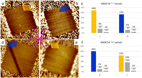
To explore the kinetic effects, the concentration of the solutions used plays a critical role. For this reason we selected concentrations slightly higher than the minimal ones reported to produce a full monolayer coverage on bare HOPG.36 In the case of ISA-OC22, the concentration that satisfied this requirement was still relatively low, therefore allowing also experiments with a higher concentration with the objective to investigate the effect of the concentration on the selection of chiral structures. To prepare all the used solutions, the solvent of choice was heptanoic acid, to remain consistent with what was previously reported.36A 5.3 × 10⁻⁴ M solution of ISA-OC14 in heptanoic acid was tested in more than 300 “+” and “−” corrals, gathered in five experimental sessions. A new experimental session begins when either the tip, the sample, or both are changed. In only two cases the formation of more than one domain was observed and the corresponding two corrals were excluded from the following statistics. The six possible rotational structures, divided in the sets of the two enantiomorphs, have all been observed inside corrals, with a non-homogeneous distribution. In particular, a large preference for one rotational domain for each enantiomorph, out of the three possible, has been observed. Such unbalance was expected, according to the previous structure selection reported for the case of ISA-OC18 in corrals.31 However, the distribution observed in the current case is different. In the current case, the presence of rotational domains is much higher than previously reported for ISA-OC18, while the observation of multiple domains in a single corral is less frequent. In addition, the domain having the unit cell vector a parallel to the slow shaving direction, i.e., the lateral border of the corral, and matching the handedness of the corral (Fig. 5a and d) which was reported for ISA-OC18 to be present in between 58% and 65% of the corrals,31 was in our case observed in only 43% of the corrals. The second most abundant structure for ISA-OC14, visible in Fig. 5b and e, which has opposite handedness with respect to the most abundant one, has been observed in 35% of the corrals. The percentages reported in the main text are calculated as a weighted average of the combined results obtained in “+” and “−” corrals.
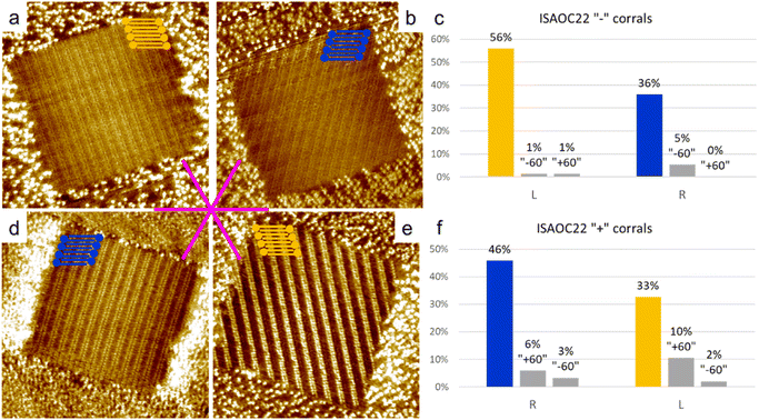
To gather information also on a longer analogue of ISA-OC18, a solution of ISA-OC22 8.3 × 10⁻⁶ M in heptanoic acid was tested in more than 300 “+” and “−” corrals gathered in 5 sessions. 25 corrals contained multiple domains and for this reason they have not been considered for the following statistics. For all the remaining cases, the self-assembled structure having the unit cell vector a parallel to the lateral border of the corral (Fig. 6a and d) was observed in 51% of the analyzed corrals. This frequency is a bit higher than the one observed in the analogous experiments performed with ISA-OC14, but still lower compared with the one previously reported of 58–65% for ISA-OC18. The second most frequent structure, having opposite handedness compared to the most frequently observed domain, visible in Fig. 6b and e, was observed in 34% of the cases. Furthermore, when comparing these results to the ones reported for ISA-OC18 in corrals,31 the trend regarding a higher presence of rotational domains and a lower presence of multiple domains contained in a single corral is similar to the one observed for ISA-OC14. Analogously, the strong preference towards the formation of one of the three possible rotational domains for each of the two enantiomorphs has been observed also in the case of ISA-OC22.
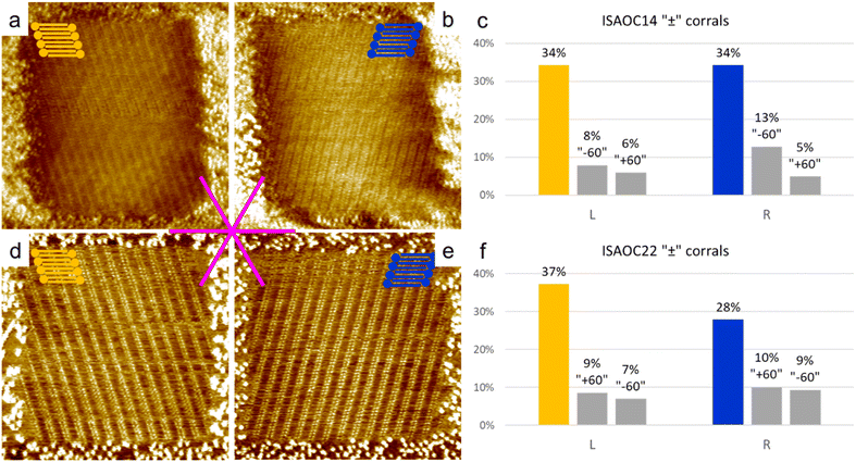
As control experiments, the same solutions of ISA-OC14 and ISA-OC22 were tested in “±” corrals, i.e., with their top border lying along one of the main symmetry axes of the substrate. In corrals having this orientation, none of the two enantiomorphic structures could form a SAMN having the lamellar structure parallel to the lateral border of the nanocontainer. In this case the favored structures observed in corrals, for ISA-OC14 as well as for ISA-OC22, were two domains, having opposite handedness, formed by ISA-OCn molecules adsorbed in corrals with their alkoxy chains parallel to the top border, i.e., the fast-shaving direction. In the more than 100 “±” corrals filled with the SAMN formed by ISA-OC14, all six possible self-assembled structures were observed, the two most frequently observed structures, being enantiomorphous, each for 34% (Fig. 7a and b). Note that if all rotational domains would be equally probable, one would expect each of them to appear in 100/6 = 16.7% of the cases. So, there is a strong preference towards certain rotational domains. As expected, there is no chirality preference. The fraction of corrals filled with “L” (“R”) lamellar structures is 48% (52%). This confirms that in absence of an external bias, the probability to observe the two structures having opposite handedness is identical. Similarly, for ISA-OC22, all six possible structures have been observed in “±” corrals (more than 100 analyzed), with the most frequently observed domain orientation for each of the enantiomorphs (Fig. 7d and e) contributing 28% (“R”) and 37% (“L”), respectively. The difference in those numbers can be attributed to experimental variations and the relatively small dataset. Aggregating the data of all domain orientations for each enantiomorph leads to the expected outcome though. Indeed, considering once again all the three types of rotational domains of the “L” (“R”) lamellar structure, this enantiomorph was observed in 53% (47%) of the total number of corrals. So, also for ISA-OC22, an equiprobability of formation of the two enantiomorphs was obtained, confirming therefore the authenticity of the bias previously observed in “+” and “−” corrals.
The distributions of self-assembled structures formed by ISA-OC14 and ISA-OC22 seem to suggest that the preferential formation of a specific structure is, to a certain extent, influenced by a different length of the alkoxy chain. In particular, a shorter alkoxy chains has a negative impact on the selection of a specific domain, even if it remains overall the one observed more frequently. On the other hand, an increase in the length of the alkoxy chain increases the frequency of observation of the domain which unit cell vector a is aligned with the corral lateral border, which, however, did not reach the previously reported level for ISA-OC18. At this point, the difference in the conditions used in this study and in the one about ISA-OC18 must be taken into account, in order to find an explanation for the differences observed. In the previously reported data, a large number of corrals containing multiple domains was reported, comparable with the number of corrals containing the favored domain. In our case, only in a limited number of corrals containing multiple domains were recorded. The explanation to the difference in the numbers of multiple domains observed is related to the different concentrations of solutions used. In our specific case, we tested two concentrations that were of a similar magnitude to the minimum concentration required for achieving monolayer coverage on bare HOPG. However, for ISA-OC18, the concentration used was approximately one order of magnitude higher than the minimum concentration needed to produce a monolayer on bare HOPG.36 This observation suggests that the nucleation rate has an important role in determining the efficiency of the selection of certain SAMNs obtained using corrals. The role of the solution concentration will be discussed in more detail later.
In the experiments presented above, where ISA-OC14 and ISA-OC22 self-assembled in “chiral” corrals, the solution concentrations were carefully selected following the same principle. For both ISA-OC14 and ISA-OC22 the concentrations used were the same order of magnitude higher than the respective minimal concentrations required to produce a full monolayer coverage on HOPG. Due to this reason, the results can be compared, revealing a minor influence of the length of the alkoxy chain of the ISA-OCn. In fact, a higher efficiency was observed in the selection of a specific SAMN for ISA-OC22. This observation suggests that a longer alkoxy chain produces more favorable conditions for the selection of a specific SAMN using corrals. This could be related to the longer aspect ratio of the molecule, which has been hypothesized previously to be a relevant parameter,33 and/or to the more favorable thermodynamic and kinetic parameters for adsorption, nucleation and growth associated with greater molecule–surface and molecule–molecule interactions caused by longer chains. Anyway, it must be noticed that the effect produced on the selective formation of SAMNs with a precise handedness of the longer alkoxy chain is not dramatic and that the difference could be due also to a statistical variability.
Chiral selection in corrals: the role of concentration
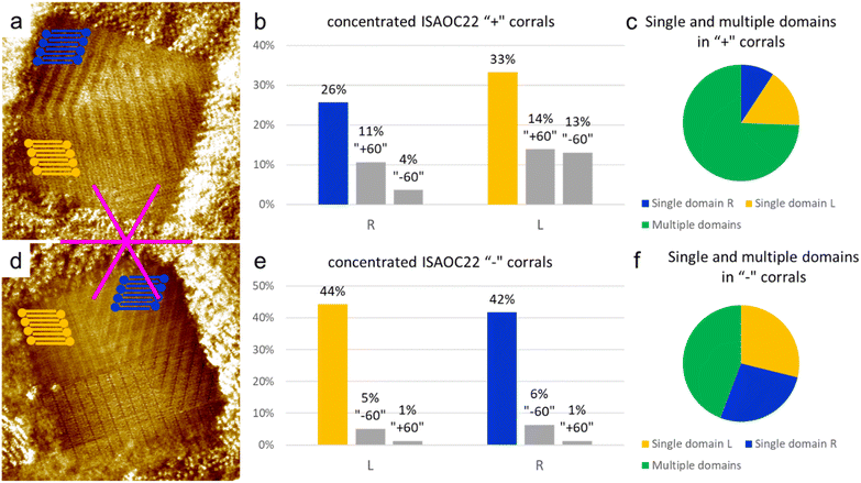
In order to further investigate the role of the concentration, and thus of the nucleation rate, on the preferential formation of specific domains, a solution of ISA-OC22 2.1 × 10⁻⁴ M in heptanoic acid was prepared. This concentration is two orders of magnitude higher than the minimal concentration reported to achieve monolayer coverage on bare HOPG.36 Such solution was used to produce a SAMN in more than 250 “chiral” corrals. In 69% of the corrals analyzed, the formation of multiple domains was observed, while in only the remaining 31% of the cases a single domain covered the whole surface of the nanocontainer. Since in this case the presence of multiple domains inside a molecular corral was the main outcome of the experiment, it could not be dismissed as a rare event that could be neglected. At this point we considered two possible statistical analyses, in order to explore the impact of the high nucleation rate on the selection of a preferential structure obtained with corrals.We first analyzed corrals containing only a single domain. We observed that among the 31% of such corrals, two structures were observed more frequently with equal probability. One was the lamellar structure with the unit cell vector a aligned with the lateral border of the corral, while the other structure corresponded to one of the rotational domains of the opposite enantiomorph. These two structures are the same as those observed as first and second most frequent outcomes in the experiment in “chiral” corrals using the lower concentration 8.3 × 10⁻⁶ M ISA-OC22 solution. Overall, in corrals containing a single domain, the coverage of the two enantiomorphs was observed to be equivalent, which means that no chiral bias was observed. However, it must be highlighted that the observed coverage is based on less than 100 corrals, from the total sample of corrals produced. Due to the statistical nature of the outcome of experiments involving self-assembly in corrals, such observations must be considered with care.
As a second way to analyze the sample of corrals collected, the orientation and handedness of all the domains observed, irrespectively of their size, was considered. In this way it was possible to consider the probability of nucleation of a certain domain, rather than its surface coverage. By comparing the incidence of multiple domains in corrals with different handedness it can be seen that the total number of counted domains is higher for “+” corrals. The probability of nucleation of multiple domains in a corral is not expected to be influenced by its orientation, but it could be influenced by many other factors that cannot be directly controlled, as for example the shape of the STM tip. Therefore, the difference between the number of “+” and “−” corrals containing multiple domains has been attributed to the statistical nature of the measurement. Considering the aggregated results of both “+” and “−” corals, it was observed that the number of domains formed by the structure with the unit cell vector a aligned to the lateral border of the coral was 28% of the total number of domains observed in all the corals. Very close to this structure was a structure of the opposite handedness, whose domains constituted 34% of the total number of domains, as displayed in Fig. 8 separately for the “+” and “−” corals. The two most frequently formed domains were observed in almost the same number of cases. However, when the rotational domains were divided into two groups corresponding to the different enantiomorphs, we observed that the opposite enantiomorph to the one matching the handedness of the considered corral (‘R’ domains matching ‘+’ corrals and ‘L’ domains matching ‘−’ corrals) now held the largest number of domains. This suggests that the nucleation of this enantiomorph is favored, which indicates a disrupting effect from an increase of the nucleation rate.
As a tentative to rationalize the observed preferential formation of a specific SAMN, based on ISA-OCn, in chiral corrals, a special consideration has been given to kinetic effects. In particular, it was hypothesized that nucleation happens simultaneously to the corrals formation and that nuclei of SAMNs whose unit cell matches the shape of the corral in formation would be able to stabilized faster, being therefore favored in the long run. The comparison between the experiments performed in this work and the data previously published31 highlights the delicate role played by the nucleation rate in the preferential formation of a specific SAMN in corrals. In fact, the initial experiments in chiral corrals, where 5.3 × 10⁻⁴ M ISA-OC14 and 8.3 × 10⁻⁶ M ISA-OC22 solution concentrations were used, demonstrated how a relatively lower concentration of ISA-OCn, and hence a lower nucleation rate, contributed in producing a broader distribution of all the possible rotational domains. The competition between the targeted structure to be grown preferentially to all other possible rotational domains in corrals, produced an overall lower selection compared to the one previously reported for a relatively higher concentration of ISA-OC18. On the other hand, when a higher concentration has been tested in chiral corrals, with the 2.1 × 10⁻⁴ M ISA-OC22 solution, a larger number of corrals containing multiple domains has been registered. Particularly important is the fact that the borders between these multiple domains do not preferentially touch the upper border of the corrals, which on the contrary happened in the reported case of ISA-OC18 in chiral corrals. This indicates that the nucleation remained competitive with the growth during the formation of the corrals. For the case of ISA-OC18, with a relative lower concentration, the majority of multiple domains touching the upper border of the corral indicated that two nuclei were stabilized preferentially during the initial stage of the corral formation almost at the same moment.31 Furthermore, considering the handedness of all the (multiple) domains observed, it was noticed that the enantiomorph opposite to the expected favorite one was formed in the largest number of domains. Even if this measure is a pure count of domains which does not tell anything on the total surface coverage, it could indicate a preferential nucleation of previously described type of structure when the nucleation rate is extremely high due to a very high solution concentration. The fact that certain domains have a higher chance to be stabilized at higher nucleation rate might be due to the shear flow created by the tip moving in solution, which can produce anisotropy in the experimental setup. Overall, the experiments reported here seem to indicate a fundamental role of the nucleation rate in determining how effective the selective formation of a preferred structure will work. In particular, when the nucleation rate is too low, the selection is disturbed by the competitive formation of different rotational domains. On the other hand, when the nucleation rate is increased by raising the concentration of the solution used, the formation of multiple domains inside a corral is observed. Additionally, in those instances the higher extent of the opposite enantiomorph compared to the expected one has been registered, showing thus a disturbance in the selection performed using corrals. To maximize the observed selection, we hypothesize that an optimal concentration is required. If the concentration is too low, it would not allow for the exploration of many different structures before one of them gets stabilized and occupies the area of the entire corrals. On the other hand, if the concentration is too high, it promotes the formation of multiple domains within a single corral, disrupting the selection achieved through confinement and nanoshaving.
Conclusions
In this work we explored the impact of several factors on the preferential formation of selected SAMNs induced by using nanocorrals. In particular, the beneficial effects of a longer alkoxy chain in enhancing the preference for the targeted SAMN have been reported. The SAMN produced by ISA-OC22 has shown to be more influenced by the process of selection using nanoconfinement. This behavior has been attributed to the longer aspect ratio of ISA-OC22 compared to ISA-OC14 and/or to the more favorable thermodynamic and kinetic parameters for adsorption, nucleation and growth associated with greater molecule–surface and molecule–molecule interactions caused by longer alkyl chains. Furthermore, the central role of the nucleation rate in determining the efficiency of the SAMNs selection observed has been discussed. It has been hypothesized that an optimal concentration, and hence nucleation rate, is required to maximize the selection of a certain SAMN using nanocorrals. In fact, when a low concentration was used, an increased competition between rotational domains was observed, while for a high concentration the formation of multiple domains in a single corral was promoted. Both these effects contribute towards lowering of the overall preferential formation of SAMNs having targeted handedness. To confirm the findings herein reported and to further expand our knowledge on the selection of SAMNs with specific characteristics by using nanocorrals, future developments are envisioned. In particular, an extensive study of the self-assembly of ISA-OCn in corrals, for solutions having different concentrations, should be carried out. Another interesting consideration is the potential impact of the molecular size-to-corral size ratio. In other words, given that the corral size is the same, does the difference in size of the molecule, irrespective of structural differences, have an impact?This work contributed to gaining new insights into the field of chiral SAMN formation. The knowledge gained in this direction will help us to direct and control chiral self-assembly with the aim of obtaining homochirality from racemic or achiral materials, thus enhancing our control over molecular chirality. While these studies do not aim to have practical applications, the impact of confinement is relevant, for instance, in nanoelectronics, where top-down lithography processes complement bottom-up self-assembly-based nanopatterning approaches. Spatial nanoconfinement is likely to impact the latter.
Author contributions
Z. T. performed all experiments involving nanoconfinement and wrote the manuscript with contributions from S. D. F. T. R. synthesized both isophthalic acid derivatives and provided the STM data on bare HOPG for comparison. All authors have given approval to the final version of the manuscript.Conflicts of interest
There are no conflicts to declare.Acknowledgements
The authors would like to acknowledge Demian Kalebić and Prof. Wim Dehaen for their help with the synthesis of ISA-OCns. Z. T. and T. R. acknowledge the FWO for the PhD fellowship for fundamental research received (fellowship numbers: 1182620N & 11F2422N). S. D. F. thanks FWO (G0E3422N, G0H2122N), KU Leuven (C14/23/090, C14/19/079), and FWO and F.R.S.– FNRS under the excellence of science (EOS) program (grant 40007495) for generous support.Notes and references
- Z. Li, Q. Fan and Y. Yin, Chem. Rev., 2022, 122, 4976–5067 CrossRef CAS PubMed.
- E. V. Amadi, A. Venkataraman and C. Papadopoulos, Nanotechnology, 2022, 33, 132001 CrossRef.
- A. Hacohen, I. Hanniel, Y. Nikulshin, S. Wolfus, A. Abu-Horowitz and I. Bachelet, Sci. Rep., 2015, 5, 12257 CrossRef CAS PubMed.
- V. A. Sontakke and Y. Yokobayashi, J. Am. Chem. Soc., 2022, 144, 2149–2155 CrossRef CAS PubMed.
- T. Mallat, E. Orglmeister and A. Baiker, Chem. Rev., 2007, 107, 4863–4890 CrossRef CAS PubMed.
- L. Pérez-García and D. B. Amabilino, Chem. Soc. Rev., 2007, 36, 941–967 RSC.
- Z. Wang, H. N. Fernández-Escamilla, J. Guerrero-Sánchez, N. Takeuchi and F. Zaera, ACS Catal., 2022, 12, 10514–10521 CrossRef CAS.
- H. Lorenz and A. Seidel-Morgenstern, Angew. Chem., Int. Ed., 2014, 53, 1218–1250 CrossRef CAS PubMed.
- B. Shen, Y. Kim and M. Lee, Adv. Mater., 2020, 32, 1905669 CrossRef CAS PubMed.
- C. B. France and B. A. Parkinson, J. Am. Chem. Soc., 2003, 125, 12712–12713 CrossRef CAS PubMed.
- M. Schöck, R. Otero, S. Stojkovic, F. Hümmelink, A. Gourdon, I. Stensgaard, C. Joachim and F. Besenbacher, J. Phys. Chem. B, 2006, 110, 12835–12838 CrossRef PubMed.
- K.-H. Ernst, Phys. Status Solidi B, 2012, 249, 2057–2088 CrossRef CAS.
- R. Raval, Chem. Soc. Rev., 2009, 38, 707–721 RSC.
- T. Chen, D. Wang and L.-J. Wan, Natl. Sci. Rev., 2015, 2, 205–216 CrossRef CAS.
- S. Dutta and A. J. Gellman, Chem. Soc. Rev., 2017, 46, 7787–7839 RSC.
- F. Zaera, Chem. Soc. Rev., 2017, 46, 7374–7398 RSC.
- Y. Xu, J.-J. Duan, Z.-Y. Yi, K.-X. Zhang, T. Chen and D. Wang, Surf. Sci. Rep., 2021, 76, 100531 CrossRef CAS.
- S. M. Barlow and R. Raval, Surf. Sci. Rep., 2003, 50, 201–341 CrossRef CAS.
- M. M. Green, M. P. Reidy, R. D. Johnson, G. Darling, D. J. O'Leary and G. Willson, J. Am. Chem. Soc., 1989, 111, 6452–6454 CrossRef.
- M. M. Green, B. A. Garetz, B. Munoz, H. Chang, S. Hoke and R. G. Cooks, J. Am. Chem. Soc., 1995, 117, 4181–4182 CrossRef CAS.
- S. Haq, N. Liu, V. Humblot, A. P. J. Jansen and R. Raval, Nat. Chem., 2009, 1, 409–414 CrossRef CAS PubMed.
- K. Tahara, H. Yamaga, E. Ghijsens, K. Inukai, J. Adisoejoso, M. O. Blunt, S. De Feyter and Y. Tobe, Nat. Chem., 2011, 3, 714–719 CrossRef CAS PubMed.
- M. Parschau, S. Romer and K.-H. Ernst, J. Am. Chem. Soc., 2004, 126, 15398–15399 CrossRef CAS PubMed.
- Y. Fang, E. Ghijsens, O. Ivasenko, H. Cao, A. Noguchi, K. S. Mali, K. Tahara, Y. Tobe and S. De Feyter, Nat. Chem., 2016, 8, 711–717 CrossRef CAS PubMed.
- I. Destoop, A. Minoia, O. Ivasenko, A. Noguchi, K. Tahara, Y. Tobe, R. Lazzaroni and S. D. Feyter, Faraday Discuss., 2017, 204, 215–231 RSC.
- N. Katsonis, H. Xu, R. M. Haak, T. Kudernac, Ž. Tomović, S. George, M. Van der Auweraer, A. P. H. J. Schenning, E. W. Meijer, B. L. Feringa and S. De Feyter, Angew. Chem., Int. Ed., 2008, 47, 4997–5001 CrossRef CAS.
- J. D. Mougous, A. J. Brackley, K. Foland, R. T. Baker and D. L. Patrick, Phys. Rev. Lett., 2000, 84, 2742–2745 CrossRef CAS PubMed.
- A. M. Berg and D. L. Patrick, Angew. Chem., Int. Ed., 2005, 44, 1821–1823 CrossRef CAS PubMed.
- J. Greenwood, T. H. Phan, Y. Fujita, Z. Li, O. Ivasenko, W. Vanderlinden, H. Van Gorp, W. Frederickx, G. Lu, K. Tahara, Y. Tobe, H. Uji-i, S. F. L. Mertens and S. De Feyter, ACS Nano, 2015, 9, 5520–5535 CrossRef CAS PubMed.
- L. Verstraete, J. Greenwood, B. E. Hirsch and S. De Feyter, ACS Nano, 2016, 10, 10706–10715 CrossRef CAS PubMed.
- J. Seibel, L. Verstraete, B. E. Hirsch, A. M. Bragança and S. De Feyter, J. Am. Chem. Soc., 2018, 140, 11565–11568 CrossRef CAS PubMed.
- Z. Tessari, K. Tahara and S. De Feyter, J. Phys. Chem. C, 2023, 127(19), 9248–9256 CrossRef CAS.
- J. Seibel, Z. Tessari, D. B. Amabilino and S. D. Feyter, Chem. Commun., 2021, 57, 61–64 RSC.
- Y. Hu, A. M. Bragança, L. Verstraete, O. Ivasenko, B. E. Hirsch, K. Tahara, Y. Tobe and S. D. Feyter, Chem. Commun., 2019, 55, 2226–2229 RSC.
- L. Verstraete, J. Smart, B. E. Hirsch and S. D. Feyter, Phys. Chem. Chem. Phys., 2018, 20, 27482–27489 RSC.
- T. Rinkovec, D. Kalebic, M. Van der Auweraer, W. Dehaen, J. N. Harvey and S. De Feyter, J. Phys. Chem. C, 2023, 127, 2025–2034 CrossRef CAS.
- S. De Feyter, A. Gesquière, M. Klapper, K. Müllen and F. C. De Schryver, Nano Lett., 2003, 3, 1485–1488 CrossRef CAS.
- F. Tao and S. L. Bernasek, Surf. Sci., 2007, 601, 2284–2290 CrossRef CAS.
- P. N. Dickerson, A. M. Hibberd, N. Oncel and S. L. Bernasek, Langmuir, 2010, 26, 18155–18161 CrossRef CAS PubMed.
| This journal is © The Royal Society of Chemistry 2024 |

