
Photoelectrochemical detection performance and mechanism discussion of Bi2O3 modified TiO2 nanotube arrays
Yajun Panga,
Guangqing Xu*a,
Chengkong Fana,
Jun Lva,
Jiaqin Liua and
Yucheng Wu*ab
aSchool of Materials Science and Engineering, Hefei University of Technology, Hefei 230009, China. E-mail: gqxu1979@hfut.edu.cn; ycwu@hfut.edu.cn; Tel: +86 551 62901372
bAnhui Provincial Key Laboratory of Advanced Functional Materials and Devices, Hefei University of Technology, Hefei 230009, China
First published on 20th June 2016
Abstract
Bi2O3 were deposited on anodized TiO2 nanotube arrays by chemical bath deposition combined with calcination. The structures, elemental compositions and morphologies of the products were investigated by X-ray diffraction, X-ray photoelectron spectroscopy, field-emission scanning electron microscopy and high resolution transmission electron microscopy respectively. The photoelectrochemical behaviors of TiO2 and Bi2O3/TiO2 NTAs were measured by cyclic votammetry and amperometry combined with a UV LED source. Modification of Bi2O3 on TiO2 nanotube arrays was found to decrease the photocurrent in buffer solution and increase the current response to organics addition at the same time, both of which are benefit for photoelectrochemical detection of organic compounds with high sensitivities. The mechanisms of Bi2O3 modification were further studied by analyzing the whole photoelectrochemical processes, including the optical absorption, charges transfer and surface electrochemical reactions. The photoelectrochemical COD sensor based on the optimized Bi2O3/TiO2 NTAs can achieve the detection performances with sensitivity of 1.8033 μA (mg L−1)−1 and COD range of 0–288 mg L−1.
1 Introduction
TiO2 nanotube arrays (NTAs) have received extraordinary attention since 2001 when the research group of Grimes fabricated them by anodic oxidation for the first time.1 TiO2 NTAs have been successfully applied to photocatalysis, solar cell, gas sensing, super capacitor and other environmental applications2–7 due to their chemical stability, thermal stability, non-toxicity, bio-compatibility, photocatalytic performance and low cost.8In recent years, the organic pollution in the water is a major concern worldwide. Many works have been endeavored to enhance the organic pollutants detection in the water. As we know, the main methods of the determination are chemical oxygen demand (COD), biochemical oxygen demand (BOD), gas chromatography (GC), and high performance liquid chromatography (HPLC).9–14 Those detection methods possess many shortcomings, such as a long period of time, consuming of expensive (Ag2SO4), corrosive (concentrated H2SO4) and highly toxic (Cr6+) chemicals and so on. TiO2 NTAs possess excellent photocatalytic activities under illumination, which can degrade the organic compounds completely. And the photoelectrochemical determination sensor based on TiO2 NTAs have been obtained by constructing the relationship among the photocurrent, holes consuming velocity and organics concentration in the solution.15
During the photoelectrochemical detection process, the photocatalytic oxygen evolution reaction on the surface of TiO2 nanotubes produces high background photocurrent, which is adverse for the determination of organic pollutants. Many efforts have been endeavored for enhancing the photoelectrochemical and photocatalytic performance of TiO2 NTAs, such as broadening optical absorption, enlarging surface area and restricting the recombination of photogenerated electron–hole pairs.16–19 However, simply enhancing the photoelectrochemical performance does not necessarily enhance the photoelectrochemical determination performance due to the complicated electrochemical reactions on the surface of TiO2 NTAs during the photoelectrochemical determination process. BiOCl nanosheets20 have been successfully deposited on TiO2 NTAs for enhancing the photoelectrochemical determination performance by controlling the holes transfer and realizing the direct oxidation of organics, which can decrease the background photocurrent and increase the current response to organics at the same time.
Here, a p-type semiconductor of Bi2O3 21 was introduced in the photoelectrochemical determination system for controlling the electrons transfer due to the appropriate coordination between the conduction bands of Bi2O3 and TiO2. Also the Bi2O3 modification on TiO2 NTAs can decrease the background photocurrent and increase the current response to organics at the same time, of course enhancing the photoelectrochemical determination performance. The different mechanisms from BiOCl modification have been deeply discussed through analyzing optical absorption, chargers transfer and surface electrochemical reactions.
2 Experimental
2.1 Chemicals and instruments
Titanium sheets with purity of 99.7% were purchased from Beijing Cuibolin Non-Ferrous Technology Developing Co., Ltd. Other chemicals, such as ammonium fluoride, ethylene glycol, bismuth nitrate, nitric acid, disodium hydrogen phosphate (Na2HPO4), sodium dihydrogen phosphate (NaH2PO4), and glucose in analytical grade were purchased from Enterprise Group Chemical Reagent Co., Ltd. Deionized water was used in all synthesis process and electrochemical tests. The supporting electrolyte used in electrochemical measurement was 0.05 M phosphate buffer solution (pH = 7) obtained by adjusting the ratio of Na2HPO4 to NaH2PO4 in the solution.TiO2 NTAs were anodized in a self-made electrolytic cell with a DC power supply (DH1722A-3) containing a Ti sheet working electrode and a graphite counter electrode. The annealing crystallization of TiO2 NTAs was performed in a muffle furnace (OTF-1200X). The photoelectrochemical performances were measured using an electrochemical workstation (CHI660D, Chenhua Instrumental Co., Ltd., Shanghai, China) combined with a UV LED light source with a maximum optical power of 1200 mW cm−2, wavelength of 365 nm and spot diameter of 10 mm. The optical power can be adjusted by controlling the electric power from 0 to 100%. X-ray diffraction patterns of the samples were recorded at room temperature with a D/MAX2500 V X-ray diffractometer using Cu Kα radiation with 2θ ranging from 10° to 90°. Morphologies of the samples were observed by a SU8020 field-emission scanning electron microscope and a JEM-2100F high resolution transmission electron microscope. The chemical compositions of Bi2O3/TiO2 NTAs were investigated by X-ray photoelectron spectroscopy (CALAB250) using Al Kα monochromatized radiation. The binding energies of the spectra were calibrated to C1s line at 284.7 eV.
2.2 Synthesis
Highly ordered TiO2 NTAs were grown from Ti sheet via electrochemical anode oxidation method in ethylene glycol solution containing 0.15 M NH4F and 5% H2O at the voltage of 60 V for 6 h. After being rinsed, the as-prepared TiO2 NTAs were ultrasonically vibrated in ethylene glycol to remove the broken nanotubes covering on the top surface of TiO2 NTAs, and then annealed in a muffle furnace at 500 °C for 2 h to get the anatase TiO2.Bi2O3 were modified on TiO2 NTAs by chemical bath deposition combined with calcination. TiO2 NTAs were immersed in beaker containing a fixed concentration of Bi(NO3)3 solution for 5 min. After that, the immersed TiO2 NTAs was calcined in a muffle furnace at 500 °C for 3 min to transform Bi(NO3)3 to Bi2O3. This process was repeated certain cycles for adjusting the depositing amount.
2.3 Photoelectrochemical performances
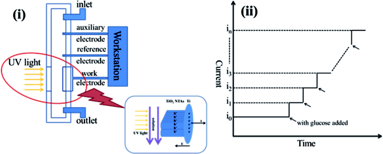
All photoelectrochemical performances and detection tests were studied in a self-made flow-injection photoelectrochemical cell based on TiO2 NTAs, comprising a photocatalytic reactor, a sampling system and a data collection system. The photocatalytic system is a thin reactor combined with a UV LED source with fixed wavelength at 365 nm, adjustable optical powers ranging from 0 to 1200 mW cm−2 and spot diameter of 10 mm. Modified TiO2 NTAs were put on a copper plate as working electrode, Ag/AgCl electrode as reference electrode and a Pt wire as auxiliary electrode. Glucose was used as target organic compound for photoelectrochemical oxidation test.Cyclic voltammograms were measured to characterize the electrochemical activity of TiO2 NTAs with sweeping potentials ranging from 0 to 1 V and a sweeping rate of 10 mV s−1. Photocurrents of Bi2O3/TiO2 NTAs were measured by amperometric method with an applied potential of 0.2 V in phosphate buffer solution. The increment of current before and after the UV light illumination gave the photocurrent response. Effect of optical power on photocurrent was measured with successively increasing the optical powers.
Organic compound detection was also performed by the amperometric method. Phosphate buffer solution was pumped into the thin cell first, and once a steady-state current was reached, glucose solution with fixed concentration was injected into the thin cell to get an increment of photocurrent, and this step was repeated as many times as possible in purpose to get the relationship between current increment and glucose concentration. Besides, it also can indicate detection limit and sensitivity of the sample.
3 Result and discussion
3.1 Characterizations
Fig. 1 shows the X-ray diffraction (XRD) patterns of as-prepared TiO2 NTAs and Bi2O3/TiO2 NTAs prepared in different conditions. It's well known that the as-anodized TiO2 NTAs are amorphous and require following annealing crystallization. Curve (a) shows the XRD pattern of annealed TiO2 NTAs with two characteristic diffraction peaks at 25.28° and 37.8°, corresponding to the (101) and (004) lattice plane of anatase phase (PDF#21-1272). There are small peaks at 40.17° and 53.004° originated from metal Ti substrate. Curve (b) shows the diffraction pattern of Bi2O3/TiO2 NTAs prepared in 20 mM Bi(NO3)3 solution for 1 cycle. The diffraction peaks are almost same with that in annealed TiO2 NTAs, and no additional diffraction peaks of Bi-containing compounds can be observed, which may be ascribed to the low amount of deposition products. For confirming the existence state of Bi-containing compounds, TiO2 NTAs were deposited in 50 mM Bi(NO3)3 solution for 10 cycles, and the phase structures of the composite were tested, as shown in curve (c). An additional diffraction peak can be observed at 30.17°, corresponding to (004) lattice plane of Bi2O3 (PDF#51-1161), indicating that Bi2O3 modified TiO2 NTAs can be obtained by this method.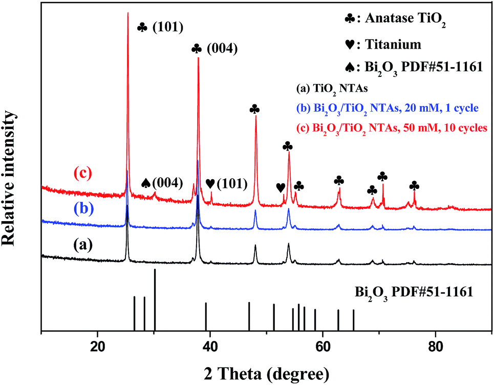 | ||
| Fig. 1 XRD patterns of as-prepared TiO2 NTAs and Bi2O3/TiO2 NTAs prepared in different conditions. | ||
X-ray photoelectron spectroscopy (XPS) analysis was conducted for investigating the surface chemical compositions and oxidation states of TiO2 and Bi2O3/TiO2 NTAs. Fig. 2 shows the XPS spectra of (a) TiO2 NTAs and (b) Bi2O3/TiO2 NTAs. The modification parameters of Bi2O3/TiO2 NTAs are Bi(NO3)3 concentration of 20 mM and deposition cycle of 1. Curve (a) shows that the main compositions of TiO2 NTAs are O and Ti with the sharp peaks of O1s and Ti2p at approximate 530.2 and 458.2 eV respectively. Peak of C1s at 284.7 eV, existing in all the samples, is originated from the testing process. Curve (b) shows the XPS spectrum of Bi2O3/TiO2 NTAs. In addition to the sharp peaks of O1s, Ti2p and C1s, the double spectra peaks at about 162 eV can be ascribed to Bi4f, comparing with curve (a). The XPS spectrum in a small energy window with high resolution was measured and shown in the inset of Fig. 2. The Bi4f electron patterns of Bi2O3/TiO2 NTAs can be divided into two binding energy peaks at 164.78 and 159.48 eV respectively. The double peaks are corresponding to 4f5/2 and 4f7/2 of Bi3+ 4f electrons, which are characteristic of Bi3+ in Bi2O3.22
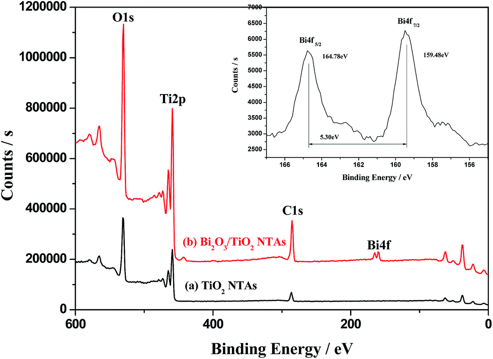 | ||
| Fig. 2 XPS spectra of TiO2 NTAs and Bi2O3/TiO2 NTAs, inset is the XPS spectra of Bi4f with high resolution. | ||
Fig. 3 shows the scanning electron microscopy (SEM) morphologies of TiO2 and Bi2O3/TiO2 NTAs. Fig. 3(i) and (ii) are top view and cross-sectional view of TiO2 NTAs. The nanotube arrays can be observed in Fig. 3(i), from which the nanotubes are tightly aligned. Fig. 3(ii) shows the profile morphology of the as-prepared TiO2 TNAs with the smooth tube walls. Fig. 3(iii) and (iv) are top view and cross-sectional view of Bi2O3/TiO2 NTAs. The Bi2O3 modified on TiO2 NTAs possesses no influence on the size and shape of TiO2 nanotubes. Although there are some irregular particles on the tube mouth and tube walls, it's difficult to differentiate the existence of Bi2O3. The EDS spectrum of Bi2O3/TiO2 NTAs is shown in Fig. 3(v), from which the existence of Bi component can be confirmed in the nanotube arrays in addition to the main components of Ti and O.
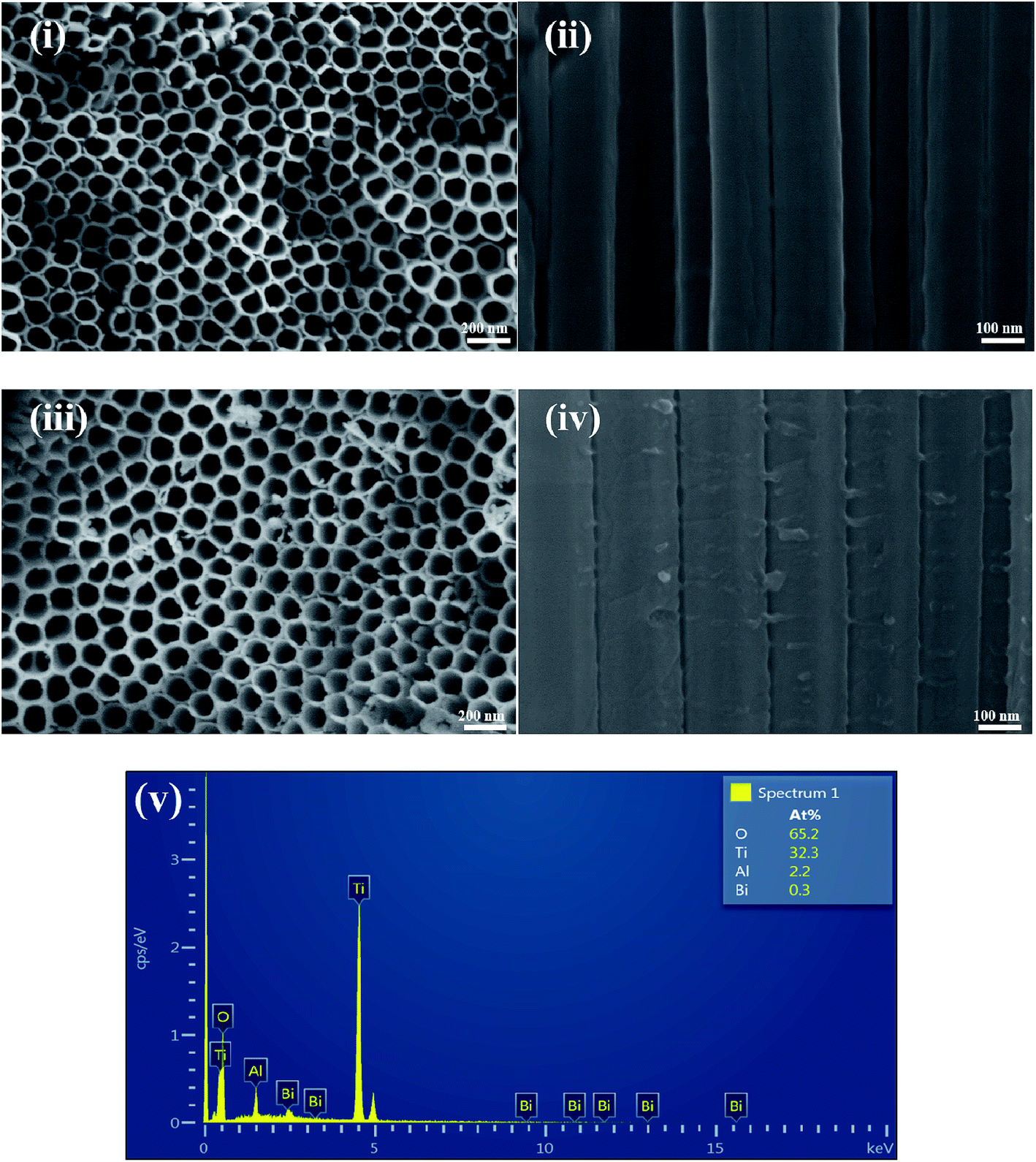 | ||
| Fig. 3 SEM morphologies of TiO2 and Bi2O3/TiO2 NTAs, top view (i) and cross-sectional view (ii) of TiO2 NTAs, top view (iii) and cross-sectional view (iv) of Bi2O3/TiO2 NTAs, (v) EDS spectrum of Bi2O3/TiO2 NTAs. Bi2O3 were deposited in 20 mM Bi(NO3)3 solution for 1 cycle. | ||
Fig. 4 shows the high resolution transmission electron microscope (HRTEM) morphologies of Bi2O3/TiO2 NTAs, the EDS pattern and the EDS elemental mapping of O, Ti and Bi. Fig. 4(i) shows the morphology of Bi2O3/TiO2 NTAs, from which the tube diameter of the nanotubes is 156 nm. It's difficult to differentiate Bi2O3 on the nanotubes due to the low amount of Bi2O3 and uneven surface of the nanotubes. The EDS pattern in Fig. 4(ii) shows the elemental composition of O, Ti, and Bi with Bi concentration of 1.4 at%. The EDS elemental mapping of O, Ti, and Bi are shown in Fig. 4(iv)–(vi), respectively. Well distribution of Bi on TiO2 nanotubes can be obtained, indicating no big aggregation of Bi2O3.
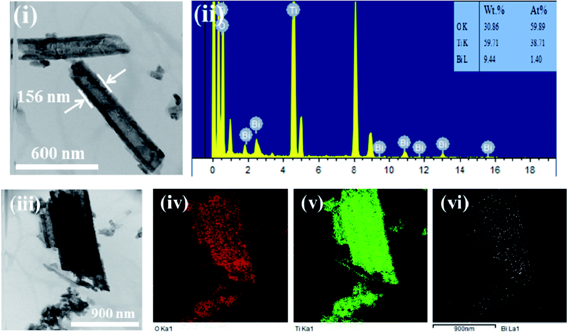 | ||
| Fig. 4 HRTEM morphologies of (i) Bi2O3/TiO2 NTAs, (ii) EDS pattern and EDS elemental mapping of (iv) O, (v) Ti and (vi) Bi, Bi2O3 were deposited in 20 mM Bi(NO3)3 solution for 1 cycle. | ||
Hence, from the discussion above, the Bi2O3 modified TiO2 NTAs were achieved by chemical bath deposition combined with calcination. When TiO2 NTAs are immersed in Bi(NO3)3 solution, the solution will be physically adsorbed on TiO2 NTAs. TiO2 NTAs contains a small amount of source solution due to the limited by the nanotubes structure during the process of immersion. And then the immersed TiO2 NTAs are calcined in a muffle furnace, which will decompose the Bi(NO3)3 into Bi2O3 on the surface of TiO2 nanotubes. Therefore, a little amount of Bi2O3 well distribute on TiO2 NTAs which can obtained from the results of the characterizations above.
3.2 Photoelectrochemical performances
Fig. 5 shows the photocurrents and current responses of TiO2 NTAs and Bi2O3/TiO2 NTAs prepared in Bi(NO3)3 solutions with different concentrations. The Bi(NO3)3 concentrations are 10 mM, 20 mM, 30 mM and 50 mM and the increment of glucose is 0.1 mM. Fig. 5(i) shows the current–time curves of TiO2 and Bi2O3/TiO2 NTAs. For unmodified TiO2 NTAs, as shown in curve (a), the sharp increase and decrease of current with light on and light off, indicating the excellent photoelectrochemical properties. The photocurrent goes up quickly when 0.1 mM glucose is added in the buffer solution, indicating the current response of TiO2 NTAs to glucose concentration. When the Bi2O3 were modified on TiO2 NTAs, as shown in curve (b–e), the photocurrents in buffer solution decrease compared with that of unmodified TiO2 NTAs, which is the background photocurrent for photoelectrochemical detection due to the photocatalytic water splitting. However, the current responses to glucose of Bi2O3/TiO2 NTAs are much higher than that of TiO2 NTAs. Both of the low background photocurrent and high current response are benefit for enhancing the detecting performances of organic compounds. Fig. 5(ii) shows the plots of photocurrent and current response vs. Bi(NO3)3 concentration. Compared with unmodified TiO2 NTAs, photocurrent decreases with the increase of modification concentration, from 114.00 μA to 83.07 μA, 42.96 μA, 40.47 μA and 16.56 μA, respectively. However, the current response increases firstly and then decreases with the modification concentration addition, the current response achieves the maximum value of 16.34 μA at 20 mM, as shown in Fig. 5(ii). Hence, the optimized modification concentration is 20 mM, which can decrease the background photocurrent and increase the current response at the same time.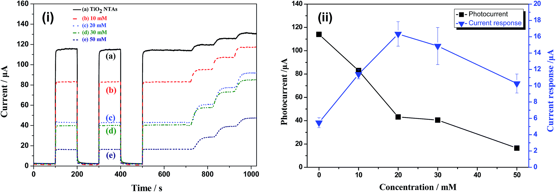 | ||
| Fig. 5 Photocurrents and current responses of TiO2 NTAs and Bi2O3/TiO2 NTAs prepared in Bi(NO3)3 solutions with different concentrations, (i) current–time curves, (ii) plots of photocurrent and current response vs. Bi(NO3)3 concentration, the deposition cycle is 1. | ||
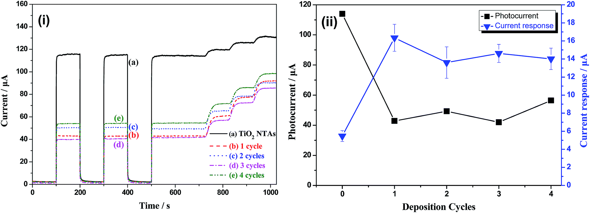
Fig. 6 shows photocurrent and current response of TiO2 NTAs and Bi2O3/TiO2 NTAs prepared in 20 mM Bi(NO3)3 solutions with different deposition cycles. Fig. 6(i) is the current–time curves of TiO2 NTAs and Bi2O3/TiO2 NTAs, confirming the decrease of background photocurrent and the increase of current response after Bi2O3 modification with different cycles. Fig. 6(ii) shows the plots of photocurrent and current response vs. deposition cycles. All the photocurrents of Bi2O3/TiO2 NTAs are much lower than that of unmodified TiO2 NTAs. Further increase of deposition cycle cannot decrease the background photocurrent anymore, and even increase a little. Besides, the current response (16.34 μA) to 0.1 mM glucose of Bi2O3/TiO2 NTAs at 1 cycle is much higher than that of unmodified TiO2 NTAs. When the deposition cycle added one by one, the current response decreases from 16.34 μA to 13.61 μA, 14.62 μA and 14.01 μA, respectively. Therefore, 1 cycle deposition of Bi2O3 is enough for enhancing the detection performances of Bi2O3/TiO2 NTAs, and further increase of deposition cycle cannot enhance the detection performance anymore.
 | ||
| Fig. 6 Photocurrents and current responses of TiO2 NTAs and Bi2O3/TiO2 NTAs prepared with different deposition cycles: (i) current–time curves, (ii) plots of photocurrent and current response vs. deposition cycles, the Bi(NO3)3 concentration is 20 mM. | ||
Cyclic voltammograms (CVs) were obtained in different conditions to study the influence of potential on electrochemical and photoelectrochemical reaction. Fig. 7 shows the CVs of TiO2 and Bi2O3/TiO2 NTAs under different conditions including in dark or under illumination, and in buffer or in 0.1 mM glucose. Fig. 7(i) shows the CVs of TiO2 NTAs in buffer solution without and with 0.1 mM glucose in dark and under illumination, respectively. Curve (a) and (b) compare CVs of TiO2 NTAs in the buffer solution without and with 0.1 mM glucose in dark. Anodic currents increase when 0.1 mM glucose is added in the buffer solution in the whole potential. The current increment increases from 1.25 μA at 0.2 V to 5.96 μA at 1.0 V, indicating that high potential promotes the electrochemical oxidation of glucose on the surface of TiO2 NTAs. Curve (a) and (c) compare the photocurrent in buffer solution in dark and under illumination respectively. Current increases in whole potential region under illumination of UV light, indicating the excellent optical response of TiO2 NTAs. The increment of the currents between in dark and under illumination shows the photocurrent, which increases with the increase of potential due to the charges separation by bias potential. The comparison of curve (c) and (d) indicates the current response to glucose of TiO2 NTAs under illumination. Current responses to glucose of TiO2 NTAs are 4.63 μA at 0.2 V and 5.7 μA at 1.0 V respectively. The difference of current responses (only 1.03 μA) between potential of 0.2 V and 1.0 V under illumination is lower than that in dark condition (4.71 μA), confirming that the change of potential possesses no effect on enhancing the photocatalytic oxidation of glucose. Fig. 7(ii) shows the CVs of Bi2O3/TiO2 NTAs under different conditions. Curve (a) shows the CV of Bi2O3/TiO2 NTAs in dark in buffer solution, from which the anodic current (16.15 μA at 1 V) is a little lower than that of TiO2 NTAs (18.34 μA at 1 V). In consideration that the current in buffer solution originates from the electrochemical water splitting, the decrease of the currents indicates lower electrochemical activity of Bi2O3/TiO2 NTAs in oxygen evolution reaction than that of TiO2 NTAs. By comparing the curve (a) and (b), it can be confirmed that the anodic current of Bi2O3/TiO2 NTAs decrease with the addition of glucose with the current increment of −2.33 μA at 1 V. The comparison of curve (a) and (c) shows the photocurrent of Bi2O3/TiO2 NTAs, which is much lower than that of TiO2 NTAs in the whole potential range. Curve (c) and (d) compare the CVs of Bi2O3/TiO2 NTAs in buffer solution in absence and presences of 0.1 mM glucose, indicating the current response of Bi2O3/TiO2 NTAs to glucose, which is much higher than that of TiO2 NTAs (from 4.63 μA to 17.97 μA at 0.2 V, 5.7 μA to 18.41 μA at 1 V). And the different potentials possess no evident effect on enhancing the current responses of Bi2O3/TiO2 NTAs, for instance, 17.97 μA at 0.2 V and 18.41 μA at 1.0 V, which confirms that potential does not enhance the photocatalytic oxidation of glucose on Bi2O3/TiO2 NTAs.
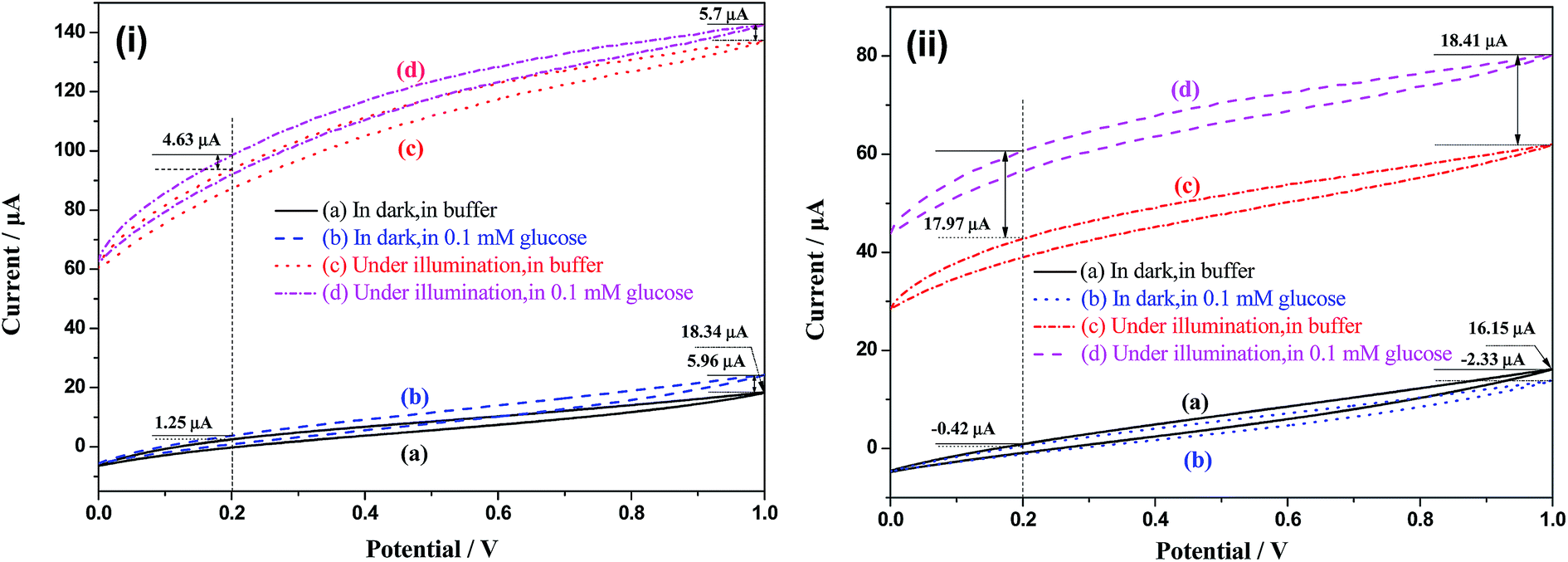 | ||
| Fig. 7 Cyclic voltammograms of (i) TiO2 and (ii) Bi2O3/TiO2 NTAs under different conditions. | ||
Fig. 8 shows the photocurrents of TiO2 and Bi2O3/TiO2 NTAs under UV light illumination with different power outputs ranging from 3% to 42% in buffer solution without and with 0.1 mM glucose. Fig. 8(i) shows the current–time curves of TiO2 and Bi2O3/TiO2 NTAs in different conditions. Photocurrent of TiO2 NTAs goes up step by step with the increase of optical power outputs, as shown in curve (a) in Fig. 8(i), indicating excellent electrochemical activity. The comparison of curve (b) and curve (a) shows that photocurrents of every step in 0.1 mM glucose solution are higher than that in buffer solution, the increments give the current response of TiO2 NTAs to 0.1 mM glucose at different optical powers. However, when the photocurrents reach about 630 μA, they no longer increase with further increase of optical power, which may be due to the limitation of electrochemical reactions on working electrode and auxiliary electrode. Limited reaction sites of the working electrode and auxiliary electrode determine the consumption velocity of photogenerated chargers. Hence, the extra electron–hole pairs will be consumed by recombination, and the photocurrents stop increasing with the further increase of optical powers.
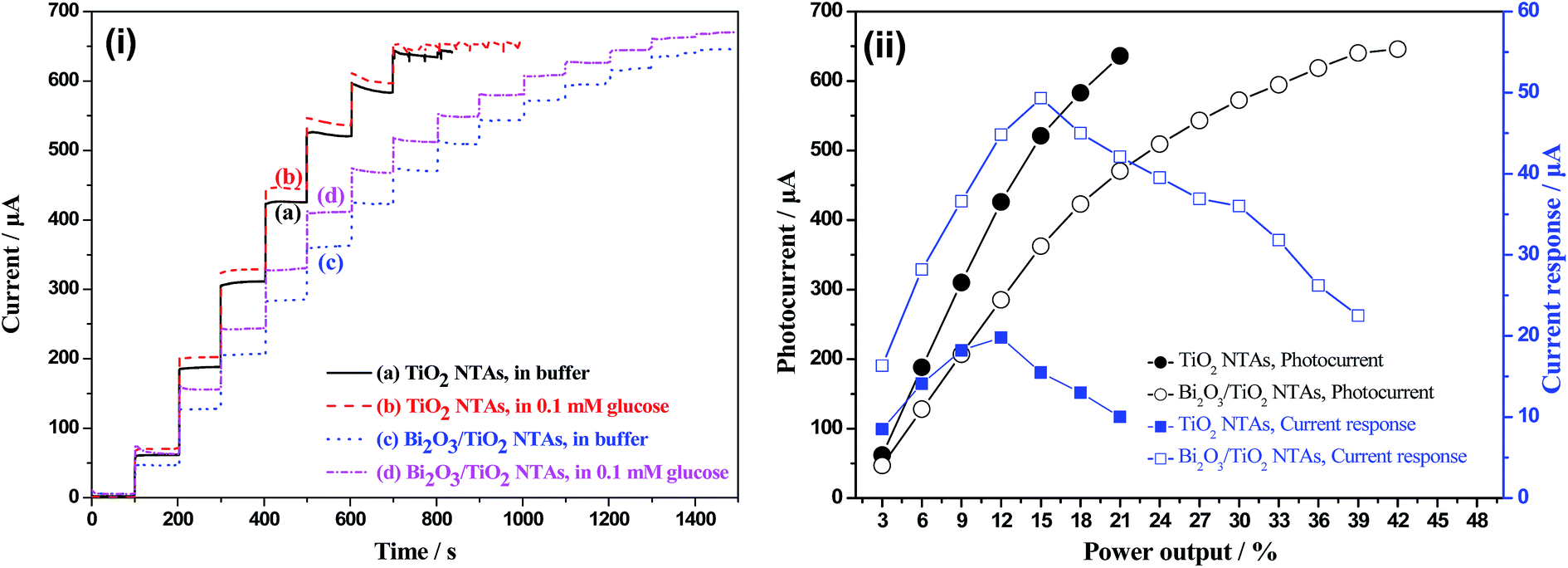 | ||
| Fig. 8 Photocurrents of TiO2 and Bi2O3/TiO2 NTAs under UV light illumination with different optical power outputs ranging from 3% to 42% in buffer and in 0.1 mM glucose, respectively: (i) current–time curves, (ii) plots of photocurrent and current response vs. power outputs. | ||
Curve (c) and (d) show the current–time curves of Bi2O3/TiO2 NTAs in buffer solutions without and with 0.1 mM glucose. All the photocurrents are lower than that of TiO2 NTAs when illuminated with the same optical powers, when the photocurrent of Bi2O3/TiO2 NTAs reach 646 μA, they no longer increase with further increase of optical power, which just as the photocurrent results of TiO2 NTAs like. And the current responses to 0.1 mM glucose obtained from curve (c) and (d) are evidently higher than that of TiO2 NTAs. Fig. 8(ii) shows the plots of photocurrent and current response vs. optical power output, from which the variation trends of photocurrent and current response to optical power can be obtained. Current response of TiO2 NTAs increase with the increase of optical power. The current responses of Bi2O3/TiO2 NTAs at all optical powers are higher than that of TiO2 NTAs, and achieve the maximum at 15% with data of 49.30 μA. However, the current response of Bi2O3/TiO2 NTAs no longer increase with further increase of optical power, which may due to the limitation of the surface reactions.
3.3 Mechanism discussion
 | ||
| Fig. 9 Schematic diagram for the photoelectrochemical progress of TiO2 and Bi2O3/TiO2 NTAs. | ||
The mechanism of photoelectrochemical determination of TiO2 NTAs is shown in Fig. 10. The photoelectrochemical determination tests were measured in a flow-injection photoelectrochemical cell,15 as shown in Fig. 10(i). Photogenerated electrons and holes of TiO2 NTAs are separated by applied potential under illumination. The photogenerated electrons transfer to Ti substrate, forming current in external circuit. The photogenerated holes transfer to surface of TiO2 NTAs, which are captured by reductive agents in the solution. The reaction of photocatalytic water splitting on TiO2 NTAs surface (oxygen evolution) produces background photocurrent as the current i0 shown in Fig. 10(ii). When organic compounds are added in the buffer solution, the anodic reaction rate increase due to the additional photocatalytic oxidation of organic compounds, which is linear to the concentration of organic compounds. The consumption rate of holes on TiO2 NTAs surface corresponds to the external currents. The relationship among organic compounds concentration, holes consuming velocity and photocurrent can be obtained.
 | ||
| Fig. 10 Schematic diagram for the mechanism of photoelectrochemical determination. | ||
3.3.2.1 Optical absorption. It is universally known that the optical absorption of materials is an important factor to its photoelectrochemical properties. Hence, the absorption patterns of TiO2 and Bi2O3/TiO2 NTAs were tested and shown in Fig. 11. Curve (a) shows the absorption pattern of TiO2 NTAs. TiO2 NTAs show excellent optical absorption performance in the UV range, fitting well with the band gap of TiO2 nanomaterials. When Bi2O3 modified on TiO2 NTAs, as shown in curve (b), the optical absorption pattern possess no much change with that of TiO2 NTAs, and also no evident absorption of visible light, it's due to the low amount of Bi2O3 on TiO2 NTAs. Especially, the optical absorption possesses almost no change at the wavelength of 365 nm used in the photoelectrochemical tests above, indicating that the optical absorption is not the main reason for the changes of photoelectrochemical performances before and after the modification of Bi2O3.
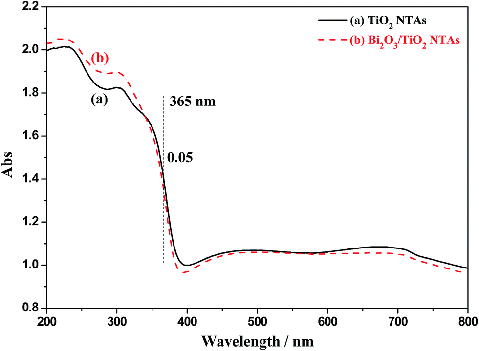 | ||
| Fig. 11 Absorption patterns of TiO2 and Bi2O3/TiO2 NTAs, Bi2O3 were deposited in 20 mM Bi(NO3)3 solution for 1 cycle. | ||
3.3.2.2 Electrons transfer. In the photoelectrochemical process, only the electrons transferring along the nanotubes to the Ti substrate can form the photocurrent in the external circuit under the effect of applied potential. Therefore, the transfer of electrons will influence the photocurrent directly. The CB of Bi2O3 is at 0.33 eV,30,31 which is more positive than that of TiO2 NTAs. When coupling TiO2 with Bi2O3, the photogenerated electrons will flow from CB of TiO2 to CB of Bi2O3, and react with dissolved oxygen to form active ·O2−. This process possesses no much adverse influence on the photocatalytic performance of TiO2 NTAs due to the photocatalytic activity of ·O2− to organic compounds. However, when used in photoelectrochemical application, as an electron trap, Bi2O3 block the electron transfer from TiO2 nanotubes to Ti substrate, resulting in the decrease of photocurrent in buffer solution.
3.3.2.3 Holes transfer. TiO2 is the main photocapture agent in the Bi2O3/TiO2 NTAs due to the low amount of Bi2O3, which can be confirmed by the similar absorption pattern of TiO2 and Bi2O3/TiO2 in Fig. 11. And the valence band (VB) of Bi2O3 is at 3.13 eV,30,31 which is more positive than that of TiO2 NTAs. Hence, when Bi2O3/TiO2 NTAs are illuminated by UV light, the generated holes on TiO2 NTAs won't transfer to the VB of Bi2O3. And small amount of photogenerated holes on Bi2O3 will transfer to VB of TiO2, which won't decrease the photocurrent. Hence, the holes transfer between TiO2 and Bi2O3 is not the reason of the decrease of photocurrent by Bi2O3 modification.
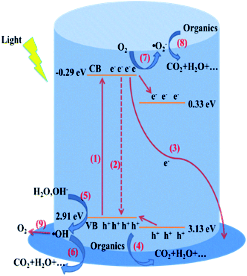
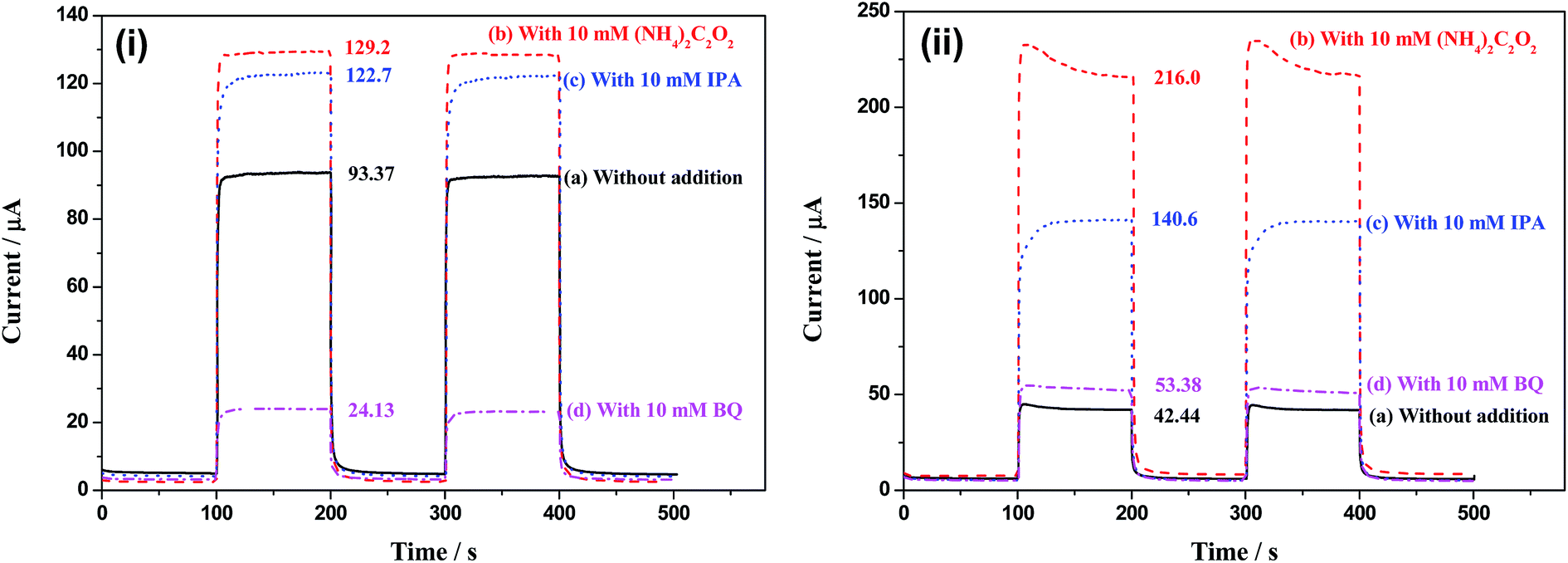
The surface electrochemical reactions have been listed in Fig. 9, containing direct oxidation of organic compounds and water splitting by holes, and indirect oxidation of organic compounds by forming ·OH and ·O2− radicals. In our previous work, we found that direct oxidation of organic compounds by holes was benefit for enhancing the photoelectrochemical determination performance.32 And BiOCl and Bi2WO6 nanosheets were modified on TiO2 NTAs promoting the holes transfer from VB of TiO2 to that of BiOCl and Bi2WO6, which can district the formation of ·OH and enhance the detection performance.20,32 However, it's much different for Bi2O3/TiO2 NTAs due to the more positive VB of Bi2O3 than that of TiO2, resulting that the holes transfer from TiO2 to Bi2O3 won't take place any more. Hence it's essential to study the effect of the different active species in the photoelectrochemical process by adding the relative trapping agents, such as ammonium oxalate ((NH4)2C2O2) for h+, isopropyl alcohol (IPA) for ·OH and benzoquinone (BQ) for ·O2−.
Fig. 12 shows the photocurrents of TiO2 and Bi2O3/TiO2 NTAs in buffer solution with additions of (NH4)2C2O2, IPA and BQ, respectively. Fig. 12(i) shows the photocurrents of TiO2 NTAs in buffer solution with additions of (NH4)2C2O2, IPA and BQ, respectively. The photocurrent of TiO2 NTAs in buffer solution is 93.37 μA. When (NH4)2C2O2 is added in the solution, the photocurrent increases to 129.2 μA, indicating that consuming holes quickly is benefit for restricting the recombination of electrons and holes, hence increase the photocurrent. When IPA is added in the solution, ·OH radicals are captured by IPA and the reaction rate of forming ·OH radicals is improved. Hence, photocurrent increases from 93.37 to 122.7 μA. It should be noted that the increment of photocurrent with addition of IPA (29.3 μA) is a little low than that with addition of (NH4)2C2O2 (35.8 μA), indicating that the indirect oxidation by forming ·OH is the main oxidation style of holes. When BQ is added in the solution, the photocurrent decreases form 93.37 to 24.13 μA. BQ is the capture agent of ·O2−, which will accelerate the reaction shown in process (7). More electrons are captured by dissolved O2 forming ·O2− radicals. Hence, the reduction of the electrons in the external circuit results in the decrease of photocurrent.
 | ||
| Fig. 12 Photocurrents of (i) TiO2 and (ii) Bi2O3/TiO2 NTAs in buffer solution with additions of (NH4)2C2O2, IPA and BQ, respectively. | ||
However, the Bi2O3/TiO2 NTAs show much different in current change with that of TiO2 NTAs with the trapping agents addition. The photocurrent of Bi2O3/TiO2 NTAs in buffer solution is only 42.44 μA, due to the electron trap effect of modified Bi2O3. The photocurrent in 10 mM (NH4)2C2O2 solution is 216.0 μA, which almost 5 times than that in buffer solution (42.44 μA), indicating that holes play key role in the photoelectrochemical oxidation process. With 10 mM IPA addition, the photocurrent increases to 140.6 μA. The increment is 98.2 μA, which is only half than induced by (NH4)2C2O2 (173.6 μA), indicating that only half holes take part in the oxidation reactions in the indirect oxidation style by forming ·OH radicals. More holes take part in the oxidation reactions by direct oxidation style, which is benefit for the organic compounds detection. With 10 mM BQ addition, the photocurrent increases a little instead of decreasing, which is much different with that in TiO2 NTAs, as shown in Fig. 12(i). BQ is the ·O2− radicals capture agent, which can accelerate of process (7) and decrease the photocurrent by consuming more electrons. No decrease and even increase of the photocurrent in Bi2O3/TiO2 NTAs with BQ addition indicates that forming ·O2− radicals is not the major method of consuming electrons due to the transfer of electrons from TiO2 to Bi2O3. The electrons on Bi2O3 surface may be captured by ·OH, forming the “external recombination” of photogenerated electrons and holes, which can explain the difference of current changes with BQ addition between TiO2 and Bi2O3/TiO2 NTAs and the decrease of indirect oxidation in the whole oxidation process.
For further discussion of the effect of ·OH radicals in the photoelectrochemical process, ·OH concentrations of TiO2 and Bi2O3/TiO2 TNAs in the solution during photoelectrochemical processes are compared by terephthalic acid oxidation method. Fig. 13 shows the photoluminescence patterns of terephthalic acid after being illuminated under UV light with (a) TiO2 and (b) Bi2O3/TiO2 NTAs. When terephthalic acid solution containing photocatalyst is illuminated under UV light, terephthalic acid can react with ·OH and the product of dihydroxy terephthalic acid shows excellent photoluminescence properties with emission peak wavelength at around 420 nm when excited by UV light at 315 nm. The emission peak intensity corresponds to ·OH concentration in solution. After being illuminated with TiO2 and Bi2O3/TiO2 NTAs, emission peak at 420 nm appears due to the product of dihydroxy terephthalic acid by the reaction between terephthalic acid and ·OH. The emission intensity of terephthalic acid treated with Bi2O3/TiO2 NTAs is a bit lower than that treated with TiO2 NTAs, which means lower ·OH concentration of Bi2O3/TiO2 NTAs than that of TiO2 NTAs in the photoelectrochemical processes. This decrement (32.3%) is much lower than that of BiOCl modification (79%)20 due to the different mechanisms. BiOCl modification transfers the holes from TiO2 to BiOCl, which possesses low productivity of ·OH. Electrons transfer from TiO2 to Bi2O3 by Bi2O3 modification and react with ·OH radicals by “external recombination” method. On the whole, the decrease of ·OH concentrations in the photoelectrochemical processes is benefit for enhancing the detection performances.
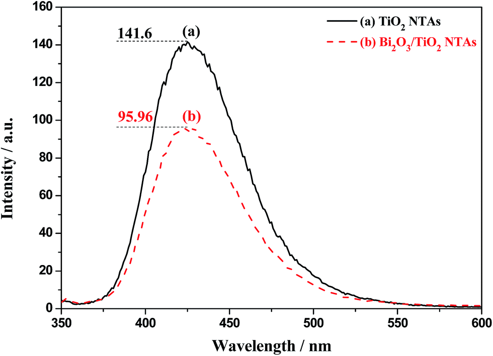 | ||
| Fig. 13 Photoluminescence patterns of terephthalic acid after being illuminated under UV light with TiO2 and Bi2O3/TiO2 NTAs, Bi2O3 were deposited in 20 mM Bi(NO3)3 solution for 1 cycle. | ||
3.4 Organics determination
Bi2O3/TiO2 NTAs possess low background photocurrent and high current response to glucose, both of which are benefit for enhancing the organics determination as a photoelectrochemical sensor. Therefore, glucose is also used as target organics for further investigating the determination performances of Bi2O3/TiO2 NTAs photoelectrochemical sensor. The amperometric response of Bi2O3/TiO2 NTAs to successive addition of glucose is shown in Fig. 14, from which the sensitivity and COD range can be obtained. Fig. 14(i) shows the current–time curves of Bi2O3/TiO2 NTAs with successive injection of glucose when illuminated with different optical powers from 3% to 12%. The sequence of glucose injections is 10 μM twice, 20 μM twice, 40 μM once, 50 μM twice and then 100 μM repeated as many times as possible. The background photocurrents of Bi2O3/TiO2 NTAs illuminated at different optical powers are much different from each other, which can be obtained from Fig. 8. Bi2O3/TiO2 NTAs possess excellent responses to glucose injection, and the current increases step by step with each glucose injection. Part of the curves are amplified for checking the current noises of the sample illuminated at different optical powers, as shown in the inset. The current noises increase a little from 0.19 to 0.30, 0.40 and 0.39 μA with the increase of optical power outputs ranging from 3% to 6%, 9% and 12%, respectively.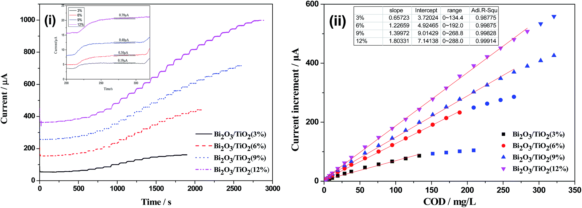 | ||
| Fig. 14 Amperometric response of Bi2O3/TiO2 NTAs photoelectrochemical sensor to successive additions of glucose in 0.05 M phosphate buffer solution: (i) current–time curve, (ii) plot of current increment vs. COD. | ||
The plots of current increment vs. COD are shown in Fig. 14(ii). These plots are linear fitted by Origin software, from which the determination performances of the photoelectrochemical sensor, such as sensitivity, COD range and detection limit (dl), can be obtained. The COD can be obtained by the decomposition reaction of glucose, and the quality of reaction glucose can be calculated accurately by the changes of glucose and solution volume. The detection limit (dl) of sensors can be calculated by dl = 3σ/m, where σ is the noise of the background current, and m is the slope of the linear part of the calibration curve. The sensitivity (slope) of Bi2O3/TiO2 NTAs (optical power output of 3%) is 0.6572 μA (mg L−1)−1, and with the increase of the optical power output, the sensitivity increase from 0.6572 to 1.2267, 1.3997 and 1.8033 μA (mg L−1)−1, respectively. Also, higher optical power can achieve wider COD range from 0 to 288 mg L−1 (12%), which much wider than that at the optical power of 3% (COD range from 0 to 134.4 mg L−1). The detection limit can be calculated based on the sensitivity of 1.8033 μA (mg L−1)−1 and current noise of 0.39 μA to be 0.2163 mg L−1.
Although high optical power is benefit for getting high sensitivity to organics determination, the influence of high optical power on background photocurrent should also be considered, as shown in Fig. 8. Macroscopic instability caused by the high background photocurrent will be adverse to the photoelectrochemical determination.
4 Conclusions
Bi2O3 are modified on TiO2 NTAs by chemical bath deposition combined with calcination method, which successfully decreases the background photocurrent and increases the current response to organics at the same time. Mechanisms of the Bi2O3 modification have been discussed by analyzing the photoelectrochemical process. The electron transfer from TiO2 to Bi2O3 play key roles on the changes of photoelectrochemical behaviors of Bi2O3/TiO2 NTAs. Electron transfer from CB of TiO2 to that of Bi2O3 decrease the photocurrent due to the electron trapping effect. The electrons on Bi2O3 possess low activity of producing ·O2− radicals, but react with ·OH radicals, which decrease the concentration of ·OH in the solution. The direct oxidation of organic compounds by holes plays key role on enhancing the current response. Both the decrease of background photocurrent and increase of current response are benefit for enhancing the photoelectrochemical detection performance. Photoelectrochemical sensor based on the Bi2O3/TiO2 NTAs achieves the optimum detection sensitivity of 1.8033 μA (mg L−1) with the COD range of 0–288 mg L−1 and the detection limit of 0.2163 mg L−1.Acknowledgements
This work was supported by Nature Science Foundation of China (51402078, 51172059 and 51272063), Fundamental Research Funds for the Central Universities (2013HGQC0005), and Nature Science Foundation of Anhui Province (1408085QE86, 1408085QE85).References
- D. Gong, C. A. Grimes, O. K. Varghese, W. C. Hu, R. S. Singh, Z. Chen and E. C. Dickey, J. Mater. Res., 2001, 16, 3331 CrossRef CAS
.
- A. Fujishima, T. N. Rao and D. A. Tryk, J. Photochem. Photobiol., C, 2000, 1, 1 CrossRef CAS
- T. Ochiai and A. Fujishima, J. Photochem. Photobiol., C, 2012, 13, 247 CrossRef CAS
- B. O'Regan and M. Grätzel, Nature, 1991, 353, 737 CrossRef
- S. A. Akbar, L. B. Younkman and P. K. Dutta, ACS Symp. Ser., 1998, 690, 161 CrossRef CAS
- H. F. Lu, F. Li, G. Liu, Z. G. Chen, D. W. Wang, H. T. Fang, G. Q. Lu, Z. H. Jiang and H. M. Cheng, Nanotechnology, 2008, 19, 405504 CrossRef PubMed
- X. Lu, G. Wang, T. Zhai, M. Yu, J. Gan, Y. Tong and Y. Li, Nano Lett., 2012, 12, 1690 CrossRef CAS PubMed
- A. Ghicov and P. Schmuki, Chem. Commun., 2009, 2791 RSC
- A. E. Greenberg, L. S. Clescent and A. D. Eaton, Standard Methods for the Examination of Water and Wastewater, American Public Health Association, Washington, DC, 18th edn, 1992 Search PubMed
- C. Preininger, I. Klimant and O. S. Wolfbeis, Anal. Chem., 1994, 66, 1841 CrossRef CAS
- J. Liu and B. Mattiasson, Water Res., 2002, 36, 3786 CrossRef CAS PubMed
- M. Rompa, E. Kremer and B. Zygmunt, Anal. Bioanal. Chem., 2003, 377, 590 CrossRef CAS PubMed
- T. R. Steinheimer, J. Agric. Food Chem., 1993, 41, 588 CrossRef CAS
- A. diCorcia and M. Marchetti, Environ. Sci. Technol., 1992, 26, 66 CrossRef CAS
- C. X. Feng, G. Q. Xu, H. P. Liu, J. Lv, Z. X. Zheng and Y. C. Wu, J. Electrochem. Soc., 2014, 161, H57 CrossRef CAS
- J. H. Park, S. Kim and A. J. Bard, Nano Lett., 2006, 6, 24 CrossRef CAS PubMed
- X. Zhang, F. Wang, H. Huang, H. Li, X. Han, Y. Liu and Z. Kang, Nanoscale, 2013, 5, 2274 RSC
- S. P. Albu, D. Kim and P. Schmuki, Angew. Chem., Int. Ed., 2008, 47, 1916 CrossRef CAS PubMed
- M. Ye, J. Gong, Y. Lai, C. Lin and Z. Lin, J. Am. Chem. Soc., 2012, 134, 15720 CrossRef CAS PubMed
- H. P. Liu, G. Q. Xu, J. W. Wang, J. Lv, Z. X. Zheng and Y. C. Wu, Electrochim. Acta, 2014, 130, 213 CrossRef CAS
- T. Xie, C. Liu, L. Xu, J. Yang and W. Zhou, J. Phys. Chem. C, 2013, 117, 24601 CrossRef CAS
- W. E. Morgan, W. J. Stec and J. R. van Wazer, Inorg. Chem., 1973, 12, 953 CrossRef CAS
- D. Bahnemann, Sol. Energy, 2004, 77, 445 CrossRef CAS
- N. M. Mahmoodi, M. Arami, N. Y. Limaee and N. S. Tabrizi, J. Colloid Interface Sci., 2006, 295, 159 CrossRef CAS PubMed
- A. Ajmal, I. Majeed, R. N. Malik, H. Idriss and M. A. Nadeem, RSC Adv., 2014, 4, 37003 RSC
- H. Park, H. I. Kim, G. H. Moon and W. Choi, Energy Environ. Sci., 2016, 9, 411 Search PubMed
- Y. Y. Zhang, Z. L. Jiang, J. Y. Huang, L. Y. Lim, W. L. Li, D. G. Gong, Y. X. Tang, Y. K. Lai and Z. Chen, RSC Adv., 2015, 5, 79479 RSC
- A. L. Linsebigle, G. Lu and J. T. Yates, Chem. Rev., 1995, 95, 735 CrossRef
- J. Bai and B. X. Zhou, Chem. Rev., 2014, 114, 10131 CrossRef CAS PubMed
- A. Hameed, T. Montini, V. Gombac and P. Fornasiero, J. Am. Chem. Soc., 2008, 130, 9658 CrossRef CAS PubMed
- J. L. Hu, H. Li, C. J. Huang, M. Liu and X. Q. Qiu, Appl. Catal., B, 2013, 142, 598 CrossRef
- Y. J. Pang, G. Q. Xu, X. Zhang, J. Lv, K. Shi, P. B. Zhai, Q. Y. Xue, X. D. Wang and Y. C. Wu, Dalton Trans., 2015, 44, 17784 RSC
| This journal is © The Royal Society of Chemistry 2016 |