 Open Access Article
Pt17 nanocluster electrocatalysts: preparation and origin of high oxygen reduction reaction activity†
Tokuhisa
Kawawaki‡
 abc,
Yusuke
Mitomi‡
a,
Naoki
Nishi
a,
Ryuki
Kurosaki
a,
Kazutaka
Oiwa
a,
Tomoya
Tanaka
a,
Hinoki
Hirase
d,
Sayuri
Miyajima
a,
Yoshiki
Niihori
 b,
D. J.
Osborn
f,
Takanori
Koitaya
ce,
Gregory F.
Metha
 f,
Toshihiko
Yokoyama
 ce,
Kenji
Iida
 *d and
Yuichi
Negishi
 *ab
*ab
aDepartment of Applied Chemistry, Faculty of Science, Tokyo University of Science, Kagurazaka, Shinjuku-ku, Tokyo 162-8601, Japan. E-mail: Kawawaki@rs.tus.ac.jp; negishi@rs.tus.ac.jp; Fax: +81-3-5261-4631; Tel: +81-3-5228-9145
bResearch Institute for Science & Technology, Tokyo University of Science, Kagurazaka, Shinjuku-ku, Tokyo 162-8601, Japan
cPhysical and Chemical Research Infrastructure Group, RIKEN SPring-8 Center, RIKEN, Sayo, Hyogo 679-5198, Japan
dInstitute for Catalysis, Hokkaido University, Sapporo, Hokkaido 001-0021, Japan
eInstitute for Molecular Science, Okazaki, Aichi 444-8585, Japan
fDepartment of Chemistry, University of Adelaide, Adelaide, South Australia 5005, Australia
First published on 24th March 2023
Abstract
We recently found that [Pt17(CO)12(PPh3)8]z (Pt = platinum; CO = carbon monoxide; PPh3 = triphenylphosphine; z = 1+ or 2+) is a Pt nanocluster (Pt NC) that can be synthesized with atomic precision in air. The present study demonstrates that it is possible to prepare a Pt17-supported carbon black (CB) catalyst (Pt17/CB) with 2.1 times higher oxygen reduction reaction (ORR) activity than commercial Pt nanoparticles/CB by the adsorption of [Pt17(CO)12(PPh3)8]z onto CB and subsequent calcination of the catalyst. Density functional theory calculation strongly suggests that the high ORR activity of Pt17/CB originates from the surface Pt atoms that have an electronic structure appropriate for the progress of ORR. These results are expected to provide design guidelines for the fabrication of highly active ORR catalysts using Pt NCs with a diameter of about 1 nm and thereby enabling the use of reduced amounts of Pt in polymer electrolyte fuel cells.
Introduction
As an option to tackle the issues of the depletion of fossil resources and global warming, our society is expected to shift from using fossil resources to using alternative sustainable energy sources such as hydrogen (H2) (Fig. S1†). The energy conversion system based on H2 involves a polymer electrolyte fuel cell (PEFC; Fig. S2†), a power generation device that produces electricity from H2 and oxygen (O2). However, current PEFCs use a large amount of platinum (Pt), which makes them expensive to manufacture and run. Though cost reduction can be achieved by improving parts other than the Pt catalyst, the continuous use of large amounts of Pt would result in a shortage of Pt. Therefore, for a sustainable hydrogen energy society, it is essential to reduce the amount of Pt used in PEFC electrocatalysts (Fig. S2†).In PEFCs, the oxygen reduction reaction (ORR) at the cathode is the rate-determining reaction, and catalysts with Pt nanoparticles (Pt NPs) of 2–3 nm in diameter supported on carbon black (Pt NPs/CB) are widely used for such cathode catalysts. However, studies by Yamamoto and co-workers,1,2 Nakajima and co-workers,3 and Fischer and co-workers4 have shown that Pt nanoclusters (NCs) of ∼1 nm in size exhibit higher ORR activity than Pt NPs of 2–3 nm in size. It is thus expected that the use of precisely synthesized Pt NCs of ∼1 nm in size as ORR electrocatalysts would afford reduced amounts of Pt to be used in PEFCs.
Pt NCs and their alloy NCs of ∼1 nm in size can be synthesized with atomic precision when carbon monoxide (CO)5,6 and phosphine (PR3) are used as ligands (Ptn(CO)m(PR3)l; n, m, l = the number of Pt atom, CO ligand, and PR3 ligand, respectively).7–9 However, most of the Ptn(CO)m(PR3)l NCs reported to date face stability issues under atmospheric conditions,7–9 and consequently few studies have been conducted on their application as ORR electrocatalysts. We recently found that [Pt17(CO)12(PPh3)8]z (z = 1+ or 2+; PPh3 = triphenylphosphine; Fig. 1(a), S3(a) and (b)†) is a Ptn(CO)m(PR3)l NC that can be synthesized and stable in air.10–12 This NC has a Pt core of ∼1 nm and can be isolated with atomic precision by a combination of simple operations: mixing reagents in air, heating the solvent, and washing the by-products. Furthermore, Pt17 is located in the size region showing the highest ORR activity.1,2 Using [Pt17(CO)12(PPh3)8]z as a precursor is expected to enable the preparation of highly active ORR electrocatalysts with Pt17 (∼1 nm in size) supported on CB (Pt17/CB). As only 17 Pt atoms are included in Pt17/CB, it is expected that density functional theory (DFT) calculations13 of Pt17/CB can be used to elucidate the origin of the high activity of the catalyst.
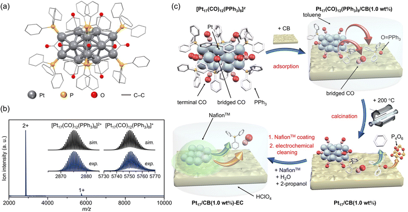 | ||
| Fig. 1 Preparation of Pt17/CB. (a) Geometric structure and (b) ESI-MS spectrum of precursor [Pt17(CO)12(PPh3)8]z. (c) Schematic of the preparation procedure: adsorption of [Pt17(CO)12(PPh3)8]z onto CB, calcination of the catalyst at 200 °C, and slurry preparation. In (c), the states of the ligand at each stage are estimated based on the results of the FT-IR spectroscopy (Fig. 3 and S10†), HAX-PES (Fig. S11†), FT-EXAFS (Fig. 4(a)), XANES (Fig. 4(b)), and TGA (Fig. S18†) analyses. | ||
In the present study, we aim to (1) engineer ORR electrocatalysts with a higher activity than that of commercial Pt NPs/CB loaded with Pt NPs of 2–3 nm in size using [Pt17(CO)12(PPh3)8]z as a precursor, and (2) elucidate the origin of the high ORR shown by Pt NCs of ∼1 nm in size by DFT calculations. As a result, we have succeeded in fabricating Pt17/CB catalyst with an ORR activity 2.1 times higher than that of commercial Pt NPs/CB. The DFT calculations strongly suggest the origin of the high activity to be attributed to the surface Pt atoms which have an electronic structure appropriate for ORR.
Results and discussion
Preparation of Pt17/CB ORR electrocatalyst using atomically precise [Pt17(CO)12(PPh3)8]Cln
The [Pt17(CO)12(PPh3)8]z ([Pt17(CO)12(PPh3)8]Cln; n = 1 or 2) precursor was synthesized by polyol reduction14–20 as in our previous reports.11 In the synthesis, an ethylene glycol solution containing Pt salts and sodium hydroxide was first heated in air. The temperature of the solution was then cooled to room temperature, and a mixture of Ptn(CO)m(PR3)l NCs was prepared by adding PPh3 to the solution. From the resulting mixture, only [Pt17(CO)12(PPh3)8]z (z = 1+ or 2+) was separated by solvent extraction. In the present study, [Pt17(CO)12(PPh3)8]z was successfully obtained with 3.8 times higher yield than that in our previous report11 by optimizing each parameter (Fig. S4;†e.g., Pt salt concentration, stirring time, amount of added PPh3) in a series of operations (Fig. S5†). The obtained product contained [Pt17(CO)12(PPh3)8]z with atomic precision, as confirmed by electrospray ionization mass spectrometry (ESI-MS; Fig. 1(b)).According to recent DFT studies,21 Ptn(CO)m(PR3)l NCs can be stabilized and isolated when the total number of valence electrons satisfies the closed shell electronic structure. In the case of Pt17(CO)12(PR3)8, [Pt17(CO)12(PR3)8]0 has been isolated in anaerobic synthetic studies because it satisfies the closed shell electronic structure (1s21p6) of the superatom at neutral state (Fig. S3(c)†).9 Our results demonstrate that (1) [Pt17(CO)12(PR3)8]0 could be oxidized in atmosphere similarly to other Ptn(CO)m(PR3)l NCs,7–9 and (2) unlike other Ptn(CO)m(PR3)l NCs, [Pt17(CO)12(PR3)8]z (z = 1+ or 2+), which does not satisfy the closed shell electronic structure, was isolated. [Pt17(CO)12(PR3)8]0 is also geometrically stabilized by the inclusion of an icosahedral metal core in the framework structure, which is a common feature in stable NCs.22–32 This seems to be the reason why [Pt17(CO)12(PPh3)8]0 could maintain its framework structure even when oxidized in air, unlike the case of other Ptn(CO)m(PR3)l NCs, and [Pt17(CO)12(PPh3)8]z (z = 1+ or 2+) selectively formed during operation in air. The high framework stability against oxidation is similar to that of [Au25(SR)18]z (Au = gold; SR = thiolate; z = 1−, 0 or 1+), which also has an icosahedral metal core.23–25
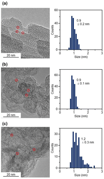
The resulting [Pt17(CO)12(PPh3)8]z NC (see Fig. 2(a) and S6† for transmission electron microscopy (TEM) images and S7† for high-angle annular dark field scanning TEM (HAADF-STEM) images) was used as a precursor to prepare the Pt17/CB catalysts. In the commercial Pt NPs/CB (TEC10E50E) used as a comparison for activity, Ketjen black, which is known as a highly conductive CB, is used as support.33 Therefore, in this study, we used Ketjen black (EC300J; hereafter described simply as CB) as a support for Pt17, unlike our previous report on ORR.34
In the catalyst preparation, CB was first added to a toluene solution of [Pt17(CO)12(PPh3)8]Cln and the solution was stirred for 24 h (Fig. 1(c)). The weight ratio of Pt to CB was set to 1.0 wt%. Analysis of the supernatant solution by inductively coupled plasma (ICP)-MS confirmed that [Pt17(CO)12(PPh3)8]z was adsorbed on CB with an adsorption rate of 98.6%. The CB (Ketjen black) contains hydroxyl and carboxyl groups,33 and hydrogen bonds are expected to form between these polar functional groups and CO. This seems to be the reason why [Pt17(CO)12(PPh3)8]z adsorbed on CB at a high adsorption rate when they were mixed at a weight ratio of 1.0 wt% Pt. In contrast, when [Pt17(CO)12(PPh3)8]z was mixed with CB at a higher weight ratio, such as 5.0 wt% Pt, [Pt17(CO)12(PPh3)8]z adsorbed on CB at a lower adsorption rate (66.6%). Under such an adsorption condition, it is difficult to control the amount of Pt loaded on the CB, and therefore, the obtained experimental data are not reproducible or reliable. Accordingly, in subsequent experiments, Pt17(CO)12(PPh3)8/CB with 1.0 wt% Pt (hereafter, Pt17(CO)12(PPh3)8/CB(1.0 wt% Pt)) was used for catalyst preparation (Fig. 2(b) and S8† for TEM images and S9† for HAADF-STEM images).
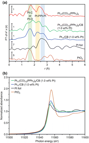
In general, the presence of ligands covering the NCs on the support prevents the approach of reactants and induces a change in the charge state of the NCs, which leads to a decrease in catalytic activity.35 Therefore, in many cases, ligands have been removed from NCs by calcination36,37 or other processes during catalyst preparation. The calcination process also plays a role in immobilizing NCs on the support. However, based on the results of the Fourier transform infrared spectroscopy (FT-IR; Fig. 3, S10 and Table S1†) and P 1s hard X-ray photoelectron spectroscopy (HAX-PES; Fig. S11†) analyses, it is assumed that in the present catalyst preparation, part of the PPh3 is oxidized to O![[double bond, length as m-dash]](https://www.rsc.org/images/entities/char_e001.gif) PPh3 during adsorption, which is then stripped from the Pt NC surface and transferred onto CB.38,39 According to the results of the FT-IR spectroscopy analysis (Fig. 3) and Pt L3-edge FT extended X-ray absorption fine structure (FT-EXAFS; Fig. 4(a)) analysis, it appears that the remaining unoxidized PPh3 migrated to the interface between Pt17 and CB (Fig. 1(c) and S12†) and thereby most of the Pt17 surface became bare after the adsorption of Pt17(CO)12(PPh3)8 onto CB. Therefore, Pt17(CO)12(PPh3)8/CB(1.0 wt% Pt) was calcined under a relatively mild condition (200 °C) in this study (Fig. 1(c) and S13†).
PPh3 during adsorption, which is then stripped from the Pt NC surface and transferred onto CB.38,39 According to the results of the FT-IR spectroscopy analysis (Fig. 3) and Pt L3-edge FT extended X-ray absorption fine structure (FT-EXAFS; Fig. 4(a)) analysis, it appears that the remaining unoxidized PPh3 migrated to the interface between Pt17 and CB (Fig. 1(c) and S12†) and thereby most of the Pt17 surface became bare after the adsorption of Pt17(CO)12(PPh3)8 onto CB. Therefore, Pt17(CO)12(PPh3)8/CB(1.0 wt% Pt) was calcined under a relatively mild condition (200 °C) in this study (Fig. 1(c) and S13†).
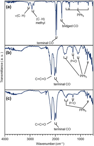 | ||
| Fig. 3 FT-IR results of each sample. (a) [Pt17(CO)12(PPh3)8]z. (b) Pt17(CO)12(PPh3)8/CB(1.0 wt% Pt). (c) Pt17/CB(1.0 wt% Pt). In (a), the peaks around 3000 cm−1 are due to 2-methyl-2-butene, which was included in the solvent (dichloromethane) as a stabilizer. Details of the peak assignments are shown in Fig. S10.† | ||
The Pt L3-edge FT-EXAFS spectra of the catalysts after calcination (Fig. 4(a) and Table S2†) displayed distinct peaks in the Pt–Pt (∼2.7 Å) and Pt–C (∼1.7 Å) bond regions (Fig. S14†), indicating that the calcination conditions employed caused immobilization of Pt17 on the CB (Fig. 1(a)). Calcination under the mild condition employed caused minimal increase in the particle size of the Pt NCs (Fig. 2(c) and S15–S17†). However, as indicated by the results in Fig. 3 and 4(a), under these mild conditions, some ligands (CO, PPh3, O![[double bond, length as m-dash]](https://www.rsc.org/images/entities/char_e001.gif) PPh3) remained in the catalyst (interface between Pt17 and CB or on CB) (Fig. 1(c) and S12†). Nevertheless, given that a higher calcination temperature of 400 °C caused a significant increase in the particle size of the Pt NCs (Fig. S18–S20†), a temperature of 200 °C was considered to be a moderate calcination temperature to prepare the fine Pt NCs-supported CB catalysts using [Pt17(CO)12(PPh3)8]z as a precursor. Pt L3-edge X-ray absorption near-edge structure (XANES; Fig. 4(b)) measurements showed that the charge state of Pt is near to Pt(0) in the resulting Pt17/CB(1.0 wt% Pt).
PPh3) remained in the catalyst (interface between Pt17 and CB or on CB) (Fig. 1(c) and S12†). Nevertheless, given that a higher calcination temperature of 400 °C caused a significant increase in the particle size of the Pt NCs (Fig. S18–S20†), a temperature of 200 °C was considered to be a moderate calcination temperature to prepare the fine Pt NCs-supported CB catalysts using [Pt17(CO)12(PPh3)8]z as a precursor. Pt L3-edge X-ray absorption near-edge structure (XANES; Fig. 4(b)) measurements showed that the charge state of Pt is near to Pt(0) in the resulting Pt17/CB(1.0 wt% Pt).
ORR activity of Pt17/CB
As described above, calcination at 200 °C allows Pt NCs to be loaded on CB while maintaining the particle size of the Pt NCs (Fig. S16†). However, it is assumed that some ligands remain adsorbed on the Pt NC surface when calcined at such a temperature. Therefore, electrochemical cleaning40,41 of Pt17/CB(1.0 wt% Pt) was performed after slurry preparation to remove remaining ligands from the catalyst (Pt17/CB(1.0 wt% Pt)-EC; Fig. 1(c) and S21†). Only negligible aggregation of Pt17 was observed after this operation (Fig. S22†), indicating that most of the Pt NCs in Pt17/CB(1.0 wt% Pt)-EC were Pt17.The ORR activity of the catalyst was evaluated by linear sweep voltammetry (LSV).42–44 In our previous report,34 we could not obtain the same mass activity for commercial Pt NPs/CB(46.9 wt% Pt) (Fig. S23†) as that reported in the literature (170–180 A g−1 for 0.9 V vs. reversible hydrogen electrode (RHE)).45 Therefore, in the present study, LSV was conducted under experimental conditions that conform to the Japanese unified standard.46 As a result, we succeeded in obtaining a mass activity (182 A g−1 for 0.9 V) close to that reported in the literature for commercial Pt NPs/CB(46.9 wt% Pt) (Fig. S24†).
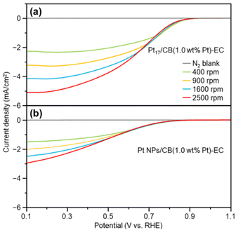
Fig. 5 shows the LSV curves of Pt17/CB(1.0 wt% Pt)-EC and Pt NPs/CB(1.0 wt% Pt)-EC (prepared by mixing Pt NPs/CB(46.9 wt% Pt) and CB). Pt17/CB(1.0 wt% Pt)-EC begins to generate a current at a lower overvoltage than Pt NPs/CB (1.0 wt% Pt)-EC and shows a higher current value at the same overvoltage (Tables S3 and S4†). These results indicate that Pt17/CB(1.0 wt% Pt)-EC has higher ORR activity than Pt NPs/CB(1.0 wt% Pt)-EC. A comparison of the mass activity at 0.9 V showed that the former had 2.1 times higher mass activity than the latter (145 vs. 68 A g−1 at 0.9 V).
In the above experiment, the Pt loading was set at 1.0 wt% to control the loading amount. This small amount of Pt on the catalyst results in fewer contacts between Pt NPs/CB and O2, leading to a lower mass activity when compared with those displayed by catalysts with higher loadings of Pt.47 Therefore, we have also prepared the Pt17/CB(20.0 wt% Pt)-EC on which 20.0 wt% Pt was loaded on CB (Fig. S25†). The electrochemical experiments on this catalyst confirmed that (1) the increase of Pt loading actually leads to the increase of the mass activity (Fig. S26(a);† 518 A g−1 for 0.9 V), (2) 4-electron reduction occurs in Pt17/CB(20.0 wt% Pt)-EC (Fig. S26(b) and (c)†), similar to the case of Pt NPs/CB(46.9 wt% Pt) (Fig. S24†), and (3) Pt17/CB(20.0 wt% Pt)-EC exhibits higher durability than commercial Pt NPs/CB (46.9 wt% Pt) (Fig. S27†).
Origin of high activity of Pt17/CB
We also investigated the origin of the high ORR activity exhibited by Pt17/CB(1.0 wt% Pt). In elucidating the factor responsible for the increase in ORR activity due to the miniaturization of Pt NPs, generally, the electrochemical surface area (ECSA) is first estimated and then the specific activity (SA) is calculated based on the value of ECSA.48 Using these two values (ECSA and SA), the main factor causing the difference in activity has been investigated: the increase in the percentage of surface Pt atoms or the improvement in the activity of each surface Pt atom. However, in such ECSA estimation, there is an assumption that the same charge flows regardless of the adsorption sites of H2 on Pt NPs. In reality, the charge flowing through the adsorption sites of H2 depends on the surface Pt atoms.49 In addition, the surface of the Pt NCs supported on CB does not necessarily consist of only one type of surface structure.50 Therefore, a discussion on the factors contributing to the differences in activity shown by the catalysts based solely on ECSA and SA calculated on the basis of these assumptions may not necessarily lead to a correct interpretation.Literature studies have reported that (1) miniaturization induces the generation of surface Pt atoms with various charge/electronic states, and (2) high ORR activity is induced when the generated surface Pt atoms contain Pt atoms suitable for ORR progression.51,52 Based on these facts, it is essential to clarify the charge and electronic states of each surface Pt atom involved in the reaction to gain a deeper understanding of the origin of the high ORR activity shown by Pt17/CB. XANES (Fig. 4(b)) and XPS experiments can reveal the overall charge state of Pt NCs, but it is difficult to reveal the charge and electronic state of each surface Pt atom using these experiments. Therefore, in the present study, we estimated the charge and electronic states of each surface Pt atom in Pt17/CB by DFT calculations. To reduce computational cost, a graphite structure,53 which is well understood, was used for the carbon support structure instead of CB structure. We obtained the optimized structure of Pt17/graphite by structural optimization using the structure of supported Pt17 observed by HAADF-STEM in our previous study14 as the initial structure (Fig. S28†).
Fig. 6(a) shows the optimized structure obtained for Pt17/graphite (Fig. S29†). In this geometry, 15 Pt atoms are located on the surface and two Pt atoms (i = 6 and 12) are in contact with graphite. Fig. 6(b) shows the charge of each Pt atom. Pt in contact with graphite (i = 6 and 12) is positively charged. This positive charging is slightly enhanced by the charge transfer from Pt to graphite (Fig. S30†).13 The Pt atoms located on the terrace (i = 1, 4, 7, and 17) are also positively charged. In contrast, the Pt atoms (i = 2, 3, 5, 8–11 and 13–16) located at the steps and corners are negatively charged. Thus, each Pt atom in Pt17/graphite has a different charge depending on its position in Pt17. Analysis of the local density of electronic states (LDOS) also revealed that each Pt atom has a different LDOS (Fig. S31†). These results indicate that Pt atoms with various charges and LDOS are present in Pt17/carbon support.4,54 We also considered the possibility of residual CO being on Pt17 and thereby performed the same structural optimization and charge and LDOS estimation at each Pt atom (CO/Pt17/graphite) in Pt17/graphite with one CO adsorbed on the Pt17 surface. The results suggest that Pt atoms of various charges and LDOS are also present in CO/Pt17/graphite, similar to the case of Pt17/graphite (Fig. S32 and S33†).
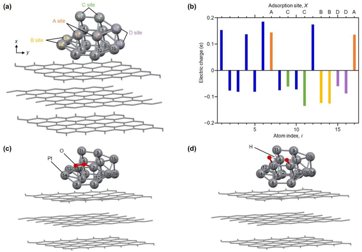 | ||
| Fig. 6 Results of DFT calculations. (a) Optimized structure of each Pt atom in Pt17/graphite. The atom index (i) of each Pt atom and site (A–D) involved in reaction with O2 are also described. (b) Electric charge of each Pt atom in Pt17/graphite. (c) Intermediate structure optimized for O2/Pt17/graphite(A). (d) Intermediate structure optimized for (O + OH)/Pt17/graphite(A). The other intermediate structures, O2/Pt17/graphite(X) and (O + OH)/Pt17/graphite(X), obtained from Pt17/graphite(X) (X = B, C, or D), are shown in Fig. S32 and S33.† | ||
To gain insight into the ORR on Pt17 NC surfaces consisting of Pt with various charges and LDOS, we performed structural optimization for the reaction intermediates in the ORR. For the adsorption sites of O2, four pairs of Pt atoms were selected as shown in Fig. 6(a) (Pt17/graphite(X); X = A, B, C, or D; Fig. S34†). The structure of the subsequent reaction intermediate was estimated by adsorbing H on the obtained structure (Fig. S35†). The results suggest the following: (1) when O2 is adsorbed on Pt17/graphite(X) (X = A, B, C, or D) (O2/Pt17/graphite(X)), the O–O bond of the adsorbed O2 is elongated regardless of the adsorption sites (Fig. 6(c) and S34 and Table S5†); (2) when H is adsorbed on such structures, the O–O bond of the adsorbed O2 dissociates readily (Fig. 6(d) and S35 and Table S6†); and (3) therefore, unlike the Pt(111) surface, the adsorption of O and OH, but not OOH, occurs on the Pt17 surface (Fig. 6(d) and Fig. S35;† (O + OH)/Pt17/graphite(X); X = A, B, C, or D). Overall, these results are in good agreement with the results of the DFT calculations on Pt13/graphite reported by Lim and Wilcox.13
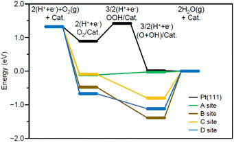
Fig. 7 shows the energy diagram55 of the ORR when a voltage of 0.9 V is applied. For comparison, Fig. 7 also shows the energy diagram of ORR on Pt(111) surface, which is included in Pt NPs/CB(46.9 wt% Pt)56 (each intermediate is O2/Pt(111), OOH/Pt(111), and (O + OH)/Pt(111)). All O2/Pt17/graphite(X) are more energetically stable than O2/Pt(111) because Pt in the Pt NCs forms stronger bonds with O than Pt on the Pt(111) surface.13 However, comparison of the four O2/Pt17/graphite(X) reveals that such stabilization is not so large for O2/Pt17/graphite(X) (X = A or C). The (O + OH)/Pt17/graphite(A) generated upon reaction at site A had the same potential as (O + OH)/Pt(111)/graphite(A). These results imply that the ORR proceeds at site A under an applied voltage of 0.9 V, similarly to Pt(111).
Further investigation of the results also revealed some differences between Pt17/graphite(A) and Pt(111). The most striking difference is that the process from O2/Pt17/graphite(A) to (O + OH)/Pt17/graphite(A) involves a moderate uphill reaction, whereas the process from O2/Pt(111) to (O + OH)/Pt(111) involves sharp uphill reactions (O2/Pt(111) → OOH/Pt(111)). This means that ORR progresses more readily on Pt17/graphite(A) than on Pt(111) surface. This is considered to be a reason why Pt17/CB(1.0 wt% Pt) shows higher ORR activity than Pt NPs/CB(1.0 wt% Pt).
Conclusions
In this study, we reported the fabrication of highly active Pt17/CB ORR catalysts using atomically precise [Pt17(CO)12(PPh3)8]z as a precursor and determined the origin of the high ORR activity shown by Pt NCs of ∼1 nm in size. Specifically, the highlights of the study are as follows:(1) Pt17/CB with 2.1 times higher ORR activity than commercial Pt NPs/CB can be obtained by the adsorption of [Pt17(CO)12(PPh3)8]z onto CB and subsequent calcination of the catalyst.
(2) Pt17 on the carbon support is composed of Pt atoms of various charges and LDOS.
(3) Dissociation into O and OH occurs on Pt17 surface in Pt17/CB without forming OOH, which is different from the case of Pt NPs/CB.
(4) Pt17/CB(1.0 wt% Pt) shows higher mass activity than Pt NPs/CB(1.0 wt% Pt) because Pt17/CB can generate surface Pt atoms that are more suitable for ORR than the Pt atoms generated on Pt(111) surface, which is included in Pt NPs/CB, due to (3) and (4).
These findings are expected to provide design guidelines for the engineering of highly active practical ORR catalysts using fine Pt NCs and thereby reducing Pt usage in PEFCs. At present, the Pt loading weight in Pt17/CB is not sufficiently controlled except the Pt17/CB(1.0 wt% Pt). Therefore, in future work, we will conduct ligand exchange57 of the precursor Pt17 NC from hydrophobic PR3 to hydrophilic PR358 to obtain Pt17/CB with higher loading amounts of Pt.
Author contributions
T. Kawawaki and Y. Negishi conceived the research and designed the experiments. T. Kawawaki, Y. M., N. N., R. K., K. O., T. T., S. M., Y. Niihori, D. J. O., T. Koitaya, G. F. M. and T. Y. performed the synthesis, characterization, and the measurements of the ORR activity. H. H. and K. I. performed DFT calculation. K. I. and Y. Negishi wrote the manuscript.Conflicts of interest
There are no conflicts to declare.Acknowledgements
We would like to thank the staff of Spring-8 BL36XU, especially Dr Tomoya Uruga, for their technical support in the HAX-PES measurements and Dr Arpan Samanta (Tokyo University of Science) for technical assistance in the early stage of the study. This study is based on results obtained from a project commissioned by the New Energy and Industrial Technology Development Organization (NEDO). This work was also supported by the Japan Society for the Promotion of Science (JSPS) KAKENHI (grant numbers 20H02698, 20H02552, and 21H04677) and Scientific Research on Innovative Areas “Hydrogenomics” (grant number 21H00027). The University of Adelaide, for scientific and technical assistance, the facilities of and scientific and technical assistance of Dr Ashley Slattery from Microscopy Australia (formerly known as AMMRF).References
- T. Imaoka, H. Kitazawa, W.-J. Chun, S. Omura, K. Albrecht and K. Yamamoto, J. Am. Chem. Soc., 2013, 135, 13089–13095 CrossRef CAS PubMed.
- T. Imaoka, H. Kitazawa, W.-J. Chun and K. Yamamoto, Angew. Chem., Int. Ed., 2015, 54, 9810–9815 CrossRef CAS PubMed.
- H. Tsunoyama, A. Ohnuma, K. Takahashi, A. Velloth, M. Ehara, N. Ichikuni, M. Tabuchi and A. Nakajima, Chem. Commun., 2019, 55, 12603–12606 RSC.
- B. Garlyyev, K. Kratzl, M. Rück, J. Michalička, J. Fichtner, J. M. Macak, T. Kratky, S. Günther, M. Cokoja, A. S. Bandarenka, A. Gagliardi and R. A. Fischer, Angew. Chem., Int. Ed., 2019, 58, 9596–9600 CrossRef CAS PubMed.
- I. Ciabatti, C. Femoni, M. C. Iapalucci, G. Longoni and S. Zacchini, J. Cluster Sci., 2014, 25, 115–146 CrossRef CAS.
- M. Paolieri, I. Ciabatti and M. Fontani, J. Cluster Sci., 2019, 30, 1623–1631 CrossRef CAS.
- I. Ciabatti, C. Femoni, M. C. Iapalucci, G. Longoni, T. Lovato and S. Zacchini, Inorg. Chem., 2013, 52, 4384–4395 CrossRef CAS PubMed.
- N. de Silva and L. F. Dahl, Inorg. Chem., 2005, 44, 9604–9606 CrossRef CAS PubMed.
- S. S. Kurasov, N. K. Eremenko, Y. L. Slovokhotov and Y. T. Struchkov, J. Organomet. Chem., 1989, 361, 405–408 CrossRef CAS.
- Y. Negishi, Phys. Chem. Chem. Phys., 2022, 24, 7569–7594 RSC.
- L. V. Nair, S. Hossain, S. Wakayama, S. Takagi, M. Yoshioka, J. Maekawa, A. Harasawa, B. Kumar, Y. Niihori, W. Kurashige and Y. Negishi, J. Phys. Chem. C, 2017, 121, 11002–11009 CrossRef CAS.
- T. Kawawaki, N. Shimizu, Y. Mitomi, D. Yazaki, S. Hossain and Y. Negishi, Bull. Chem. Soc. Jpn., 2021, 94, 2853–2870 CrossRef CAS.
- D.-H. Lim and J. Wilcox, J. Phys. Chem. C, 2012, 116, 3653–3660 CrossRef CAS.
- Y. Negishi, N. Shimizu, K. Funai, R. Kaneko, K. Wakamatsu, A. Harasawa, S. Hossain, M. E. Schuster, D. Ozkaya and W. Kurashige, Nanoscale Adv., 2020, 2, 669–678 RSC.
- H. Dong, Y. C. Chen and C. Feldmann, Green Chem., 2015, 17, 4107–4132 RSC.
- F. Fievet, J. P. Lagier and M. Figlarz, MRS Bull., 1989, 14, 29–34 CrossRef CAS.
- C. Bock, C. Paquet, M. Couillard, G. A. Botton and B. R. MacDougall, J. Am. Chem. Soc., 2004, 126, 8028–8037 CrossRef CAS PubMed.
- C. M. Pelicano, M. Saruyama, R. Takahata, R. Sato, Y. Kitahama, H. Matsuzaki, T. Yamada, T. Hisatomi, K. Domen and T. Teranishi, Adv. Funct. Mater., 2022, 32, 2202987 CrossRef CAS.
- B.-J. Hwang, L. S. Sarma, C.-H. Chen, C. Bock, F.-J. Lai, S.-H. Chang, S.-C. Yen, D.-G. Liu, H.-S. Sheu and J.-F. Lee, J. Phys. Chem. C, 2008, 112, 19922–19929 CrossRef CAS.
- I. Schrader, J. Warneke, S. Neumann, S. Grotheer, A. A. Swane, J. J. K. Kirkensgaard, M. Arenz and S. Kunz, J. Phys. Chem. C, 2015, 119, 17655–17661 CrossRef CAS.
- J. Wei, R. Marchal, D. Astruc, S. Kahlal, J.-F. Halet and J.-Y. Saillard, Nanoscale, 2022, 14, 3946–3957 RSC.
- C. Femoni, M. C. Iapalucci, G. Longoni, S. Zacchini and S. Zarra, J. Am. Chem. Soc., 2011, 133, 2406–2409 CrossRef CAS PubMed.
- S. Antonello, N. V. Perera, M. Ruzzi, J. A. Gascón and F. Maran, J. Am. Chem. Soc., 2013, 135, 15585–15594 CrossRef CAS PubMed.
- M. Zhu, C. M. Aikens, M. P. Hendrich, R. Gupta, H. Qian, G. C. Schatz and R. Jin, J. Am. Chem. Soc., 2009, 131, 2490–2492 CrossRef CAS PubMed.
- M. A. Tofanelli, K. Salorinne, T. W. Ni, S. Malola, B. Newell, B. Phillips, H. Häkkinen and C. J. Ackerson, Chem. Sci., 2016, 7, 1882–1890 RSC.
- Y. Shichibu and K. Konishi, Small, 2010, 6, 1216–1220 CrossRef CAS.
- B. K. Teo and H. Zhang, Coord. Chem. Rev., 1995, 143, 611–636 CrossRef CAS.
- N. Yan, N. Xia, L. Liao, M. Zhu, F. Jin, R. Jin and Z. Wu, Sci. Adv., 2018, 4, eaat7259 CrossRef CAS PubMed.
- Y. Negishi, W. Kurashige, Y. Niihori, T. Iwasa and K. Nobusada, Phys. Chem. Chem. Phys., 2010, 12, 6219–6225 RSC.
- E. Ito, S. Takano, T. Nakamura and T. Tsukuda, Angew. Chem., Int. Ed., 2021, 60, 645–649 CrossRef CAS PubMed.
- M. Laupp and J. Strähle, Angew. Chem., Int. Ed. Engl., 1994, 33, 207–209 CrossRef.
- M. Akutsu, K. Koyasu, J. Atobe, N. Hosoya, K. Miyajima, M. Mitsui and A. Nakajima, J. Phys. Chem. A, 2006, 110, 12073–12076 CrossRef CAS PubMed.
- D. Tashima, H. Yoshitama, M. Otsubo, S. Maeno and Y. Nagasawa, Electrochim. Acta, 2011, 56, 8941–8946 CrossRef CAS.
- T. Kawawaki, N. Shimizu, K. Funai, Y. Mitomi, S. Hossain, S. Kikkawa, D. J. Osborn, S. Yamazoe, G. F. Metha and Y. Negishi, Nanoscale, 2021, 13, 14679–14687 RSC.
- T. Kawawaki, Y. Kataoka, M. Hirata, Y. Iwamatsu, S. Hossain and Y. Negishi, Nanoscale Horiz., 2021, 6, 409–448 RSC.
- T. Kawawaki, Y. Kataoka, M. Hirata, Y. Akinaga, R. Takahata, K. Wakamatsu, Y. Fujiki, M. Kataoka, S. Kikkawa, A. S. Alotabi, S. Hossain, D. J. Osborn, T. Teranishi, G. G. Andersson, G. F. Metha, S. Yamazoe and Y. Negishi, Angew. Chem., Int. Ed., 2021, 60, 21340–21350 CrossRef CAS PubMed.
- T. Kawawaki, Y. Kataoka, S. Ozaki, M. Kawachi, M. Hirata and Y. Negishi, Chem. Commun., 2021, 57, 417–440 RSC.
- D. P. Anderson, J. F. Alvino, A. Gentleman, H. Al Qahtani, L. Thomsen, M. I. J. Polson, G. F. Metha, V. B. Golovko and G. G. Andersson, Phys. Chem. Chem. Phys., 2013, 15, 3917–3929 RSC.
- D. P. Anderson, R. H. Adnan, J. F. Alvino, O. Shipper, B. Donoeva, J.-Y. Ruzicka, H. Al Qahtani, H. H. Harris, B. Cowie, J. B. Aitken, V. B. Golovko, G. F. Metha and G. G. Andersson, Phys. Chem. Chem. Phys., 2013, 15, 14806–14813 RSC.
- Y. Lu, Y. Jiang, X. Gao and W. Chen, Chem. Commun., 2014, 50, 8464–8467 RSC.
- L. Lu, S. Zou, Y. Zhou, J. Liu, R. Li, Z. Xu, L. Xiao and J. Fan, Catal. Sci. Technol., 2018, 8, 746–754 RSC.
- Z. Peng and H. Yang, J. Am. Chem. Soc., 2009, 131, 7542–7543 CrossRef CAS PubMed.
- L. Wang, Z. Tang, W. Yan, H. Yang, Q. Wang and S. Chen, ACS Appl. Mater. Interfaces, 2016, 8, 20635–20641 CrossRef CAS PubMed.
- L. Sumner, N. A. Sakthivel, H. Schrock, K. Artyushkova, A. Dass and S. Chakraborty, J. Phys. Chem. C, 2018, 122, 24809–24817 CrossRef CAS.
- G. Samjeské, S.-i. Nagamatsu, S. Takao, K. Nagasawa, Y. Imaizumi, O. Sekizawa, T. Yamamoto, Y. Uemura, T. Uruga and Y. Iwasawa, Phys. Chem. Chem. Phys., 2013, 15, 17208–17218 RSC.
- M. Mench, E. C. Kumbur and T. N. Veziroglu, Polymer electrolyte fuel cell degradation, Academic Press, Cambridge, 2011 Search PubMed.
- S. H. Joo, K. Kwon, D. J. You, C. Pak, H. Chang and J. M. Kim, Electrochim. Acta, 2009, 54, 5746–5753 CrossRef CAS.
- M. Shao, A. Peles and K. Shoemaker, Nano Lett., 2011, 11, 3714–3719 CrossRef CAS PubMed.
- H. Ogasawara and M. Ito, Chem. Phys. Lett., 1994, 221, 213–218 CrossRef CAS.
- R. K. Bera, H. Park, S. H. Ko and R. Ryoo, RSC Adv., 2020, 10, 32290–32295 RSC.
- F. Calle-Vallejo, J. Tymoczko, V. Colic, Q. H. Vu, M. D. Pohl, K. Morgenstern, D. Loffreda, P. Sautet, W. Schuhmann and A. S. Bandarenka, Science, 2015, 350, 185–189 CrossRef CAS PubMed.
- B. Garlyyev, J. Fichtner, O. Piqué, O. Schneider, A. S. Bandarenka and F. Calle-Vallejo, Chem. Sci., 2019, 10, 8060–8075 RSC.
- D. Tománek and S. G. Louie, Phys. Rev. B: Condens. Matter Mater. Phys., 1988, 37, 8327–8336 CrossRef PubMed.
- G. Ramos-Sanchez and P. B. Balbuena, Phys. Chem. Chem. Phys., 2013, 15, 11950–11959 RSC.
- H. A. Hansen, J. Rossmeisl and J. K. Nørskov, Phys. Chem. Chem. Phys., 2008, 10, 3722–3730 RSC.
- K. i. Miyazawa, S. Shimomura, M. Yoshitake and Y. Tanaka, Int. J. Eng. Res. Ind. Appl., 2018, 8, 13–21 Search PubMed.
- W. Kurashige, R. Hayashi, K. Wakamatsu, Y. Kataoka, S. Hossain, A. Iwase, A. Kudo, S. Yamazoe and Y. Negishi, ACS Appl. Energy Mater., 2019, 2, 4175–4187 CrossRef CAS.
- L. K. Batchelor, B. Berti, C. Cesari, I. Ciabatti, P. J. Dyson, C. Femoni, M. C. Iapalucci, M. Mor, S. Ruggieri and S. Zacchini, Dalton Trans., 2018, 47, 4467–4477 RSC.
Footnotes |
| † Electronic supplementary information (ESI) available: Experimental section (Fig. S36–S39), calculation method, additional tables, additional figures, additional MALDI-MS, FT-IR, XPS, EXAFS spectra, TEM images, TG curves, CV, LSV curves, and optimized structures. See DOI: https://doi.org/10.1039/d3nr01152f |
| ‡ These authors contributed equally. |
| This journal is © The Royal Society of Chemistry 2023 |

