Improving the electrochemical performance of a lithium–sulfur battery with a conductive polymer-coated sulfur cathode†
Yanrong Li,
Lixia Yuan*,
Zhen Li,
Yizi Qi,
Chao Wu,
Jing Liu and
Yunhui Huang*
State Key Laboratory of Material Processing and Die & Mould Technology, School of Materials Science and Engineering, Huazhong University of Science and Technology, Wuhan, Hubei 430074, China. E-mail: yuanlixia@hust.edu.cn; huangyh@hust.edu.cn; Fax: +86 2787558241; Tel: +86 2787558241
First published on 8th May 2015
Abstract
Low sulfur utilization, poor cycle life, and the security problems caused by a Li metal anode are the main drawbacks hindering the practical application of lithium–sulfur batteries. Here we report a facile modification of the traditional sulfur cathode to achieve a high capacity and considerably improved cycle life. By coating a commercially-purchased conductive polymer PEDOT:PSS onto the surface of a pristine sulfur electrode, a significant enhancement is achieved in both sulfur utilization and capacity retention. With this strategy, gravimetric energy densities of the cell with the modified S cathode are estimated to 1113 W h kg−1 based on the total composition of the electrode. The PEDOT:PSS film not only serves as a soft buffer to restrict the polysulfides immigrating to the lithium anode, suppresses mechanical stress and sustains a stable electrode, but also provides more active surfaces to capture and reutilize the polysulfides.
Introduction
An urgent demand for electric vehicles (EVs) has arisen with the increasingly serious energy and environmental issues, which promotes the rapid development of rechargeable batteries with high energy density worldwide.1 Among all the redox couples of rechargeable batteries, a lithium–sulfur couple has a very high theoretical energy density of 2600 W h kg−1 or 2800 W h L−1 based on a two-electron complete reaction: S8 + 16Li+ + 16e ⇄ 8Li2S,2,3 much higher than those of traditional lithium-ion batteries (LIBs). In addition, sulfur has advantages of low cost, environmental benignity and nontoxicity.4–6 Thus, a lithium–sulfur battery is considered as a promising candidate for next-generation high energy storage systems.Although there are many advantages of lithium–sulfur battery, successful application is still hindered by low sulfur utilization and rapid capacity fading.7 The problems are mainly caused by the insulating nature of sulfur and the final discharge product (Li2S), and the dissolution of long-chain polysulfides generated during discharge–charge process.8,9 In addition, the volume expansion of sulfur during the lithiation process is as large as 80% due to the density difference between sulfur and Li2S,10–12 which also results in structure collapse of the cathode and degradation of battery performance. Besides, the safety and engineering difficulties related to Li metal anode are also tough challenges.13,14
Lots of efforts have been devoted to overcoming above problems, especially with the influx of nanotechnologies, great progress has been achieved in the field of lithium–sulfur battery in recent years. One of the most important strategies is to impregnate sulfur into various carbon structures.15–18 By constraining the growth of sulfur nanofiller within the pores of the conductive porous carbon matrix, the conductivity of sulfur electrode can be greatly improved, and the dissoluble loss of sulfur in the liquid electrolyte can also be restrained, leading to a remarkably improved electrochemical performance. In this way, some nano-architectured sulfur composites have been reported to exhibit specific capacity over 1000 mA h g−1 (ref. 9, 19 and 20) or show excellent cyclability up to hundreds of times.21–23
However, almost all the capacity data reported in lithium–sulfur batteries were calculated only based on the mass of sulfur. In fact, a large fraction of carbon is used to enhance the conductivity and suppress the dissolution of polysulfides, thus the S content in the whole cathode is always less than 50%.24–27 Since the carbon matrix can hardly contribute capacity to the sulfur cathode, the volumetric energy density for lithium–sulfur batteries is difficult to exceed the traditional LIBs except on the condition that S loading is high enough (>70%).28 However, little attention has been paid to this point. On the other hand, fabrication of the nano-architectured sulfur composites usually requires complicated procedures, involving high-temperature process and corrosive acid for template removal. Such procedures may greatly limit the manufacturability of S cathode. Therefore, it is highly desirable to develop a simple and scalable approach to fabricate S cathode with high overall capacity over long-term cycling.
Polymers also have been used to couple with S for their abundant controllable morphologies and physical and chemical properties.29–31 But unlike carbon materials which are widely used as sulfur supporters, polymers have been used mostly as coating layers for S31–33 or S/C materials.34,35 For example, with a simple PEG-coating, Ji et al.15 reported that a stable capacity of CMK-3/S composite can be improved from 900 mA h g−1 to over 1100 mA h g−1. Cui et al.36 has also reported a conductive polymer wrapped CMK-3/S composite. With PEDOT:PSS coating, the CMK-3/S composite showed a high initial reversible capacity of 1140 mA h g−1 and a good cyclability with a decay of 15% per 100 cycles. While in these two unique designs, the preparation of CMK-3 is elaborate, and the subsequent combination with sulfur needs to melt and infuse S into the carbon matrix, which are not suitable for large-scale production.
Here we proposed a modified S cathode prepared via a very simple method. Commercially-purchased poly(3,4-ethylenedioxythiophene):poly(styrenesulfonate) (PEDOT:PSS) aqueous solution was pasted onto a pristine S electrode prepared by a traditional process. Then, a thin but dense and stable film was formed after drying. In this system, the PEDOT:PSS film not only serves as a soft buffer to restrict polysulfides immigrating to lithium anode, suppress mechanical stress and sustain a stable electrode, but also provides abundant active surfaces to capture and reutilize the polysulfides, as shown in Fig. 1. Such a super-simple modification for sulfur cathode can give a largely improved stability for the lithiation–delithiation process. Since the PEDOT:PSS layer is very thin and light, which occupies less than 5 wt% of the total electrode, there is no obvious negative effect on the total gravimetric or volumetric capacities of sulfur cathode. Moreover, unlike the previous reports in which the polymers are coated on S31–33 or S/C15,34–36 particles, here the conductive PEDOT:PSS is coated on the S electrode, which successfully avoid the widely-used top-down route to melt and infuse S into the matrix. Therefore the PEDOT:PSS-modified sulfur cathode can be directly prepared by the present Li-ion battery production line.
 | ||
| Fig. 1 Illustration of lithium–sulfur battery configuration: (a) conventional lithium–sulfur battery, (b) lithium–PEDOT:PSS-modified sulfur battery. | ||
Experimental
Preparation of pristine S cathode and PEODT:PSS-coated S cathode
The pristine sulfur cathode was prepared by mixing 0.06 g sublimed sulfur, 0.03 g carbon black (Super-P), 0.005 g styrene butadiene rubber (SBR) and 0.005 g carboxyl methyl cellulose sodium salt (NaCMC) in deionized water to form homogeneous slurry. The slurry was coated onto Al foil by doctor blade method with an active material loading of about 0.75–0.98 mg cm−2, and dried at 80 °C overnight in an oven. Then 500 μL PEDOT:PSS aqueous solution (1.3 wt%, Sigma-Aldrich) was coated on the as-prepared S cathode by doctor blade method, followed by drying at 80 °C for 24 h. The dried electrode film was then roll-pressed, and cut into round disks with diameter of 8 mm. According to the quality changes before and after coating, the weight ratio of PEDOT:PSS in the electrode (excluding the current collector) can be determined as ∼4.5 wt%.Characterizations
The morphologies of cathodes were observed by scanning electron microscopy (SEM, FEI, SIRION200). X-ray photoelectron spectroscopy (XPS) measurement was carried out on a Kratos Analytical spectrometer (AXIS ULTRA DLD-600W) with X-ray source of Al Kα (1486.6 eV).Electrochemical measurements
CR2032 coin cells were assembled and well sealed in Ar-filled glove box for electrochemical tests. The electrolyte was 1 mol L−1 LiTFSI (1,1,1-trifluoro-n-[(trifluoromethyl)sulfonyl]-methanesulfonamide-lithium salt) in a mixture of 1,3-dioxolane (DOL) and dimethoxymethane (DME) (1/1, v/v) with 0.2 mol L−1 LiNO3 as an addictive. Lithium metal was used as anode and Celgard 2300 membrane was used as separator. Cyclic voltammogram (CV) curves were recorded on an electrochemical workstation (CHI614b) at a scanning rate of 0.1 mV s−1 in the voltage range between 3.0 and 1.7 V vs. Li/Li+ at room temperature. Galvanostatic discharge–charge tests were carried out at various current densities of 0.1–2 C at room temperature on a Battery Measurement System (Land, China). The specific capacity was calculated based on the mass of sulfur, and the rate was calculated according to the theoretical capacity of sulfur (1675 mA h g−1).Results and discussion
The SEM images in Fig. 2 reveal the morphology change of the S electrode before and after PEDOT:PSS coating. The pristine S cathode displays a rough surface with well-dispersed S particles (Fig. 2a). After PEDOT:PSS coating, the electrode surface becomes smooth and dense (Fig. 2b). From Fig. S1,† we can see that the surface of PEDOT:PSS-coated S cathode is also pretty uniform in low magnification. Fig. 2c gives a contrast from a sulfur electrode partly covered by PEDOT:PSS film, which clearly shows that the PEDOT:PSS film is tightly coated on the S cathode surface. XPS measurement was carried out to further confirm the existence of PEDOT:PSS film. Fig. 3 shows the S 2p peak of pristine S cathode, pure PEDOT:PSS film and the PEDOT:PSS-coated S cathode. The pristine S cathode shows two characteristic peaks of element sulfur at 164.0 and 165.2 eV. For pure PEDOT:PSS, four peaks can be fitted: the two peaks located at higher binding energy of 168.7 and 167.5 eV are assigned to PSS, and the other two at 165.3 and 163.8 eV are attributed to PEDOT.36 The PEDOT:PSS-coated S cathode exhibits similar characteristic peaks to the pure PEDOT:PSS, but the two peaks located at lower binding energy displays higher relative intensity due to the overlap of elemental S and S in PEDOT. As XPS is a surface detective method with a detective depth around 10 nm, it can be speculated that this additional PEDOT:PSS layer is quite thin. It can be inferred that negative effect on gravimetric and volumetric capacities of the sulfur cathode should be very small.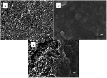 | ||
| Fig. 2 SEM images of (a) pristine S cathode, (b) PEDOT:PSS-coated S cathode, and (c) PEDOT:PSS partly-coated S cathode. | ||
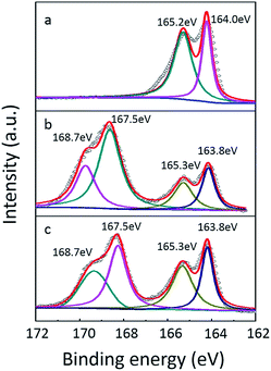 | ||
| Fig. 3 XPS spectra of (a) pristine S cathode, (b) pure PEDOT:PSS and (c) PEDOT:PSS-coated S cathode. | ||
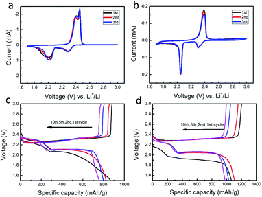
The electrochemical properties of sulfur cathodes with and without PEDOT:PSS coating were investigated with coin cells. All the cells were assembled and sealed in the same condition. Fig. 4a and b shows CV curves of the first 3 cycles for the sulfur cathodes without and with PEDOT:PSS coating. Both curves show two distinct reduction peaks and one oxidation peak, which agrees well with the typical CV characteristics of sulfur cathode. The two peaks at 2.25 and 2.05 V correspond to the reduction of S8 to higher-order polysulfides (Li2Sx, 4 < x < 8), and then to Li2Sx (x = 1, 2). The intense oxidation peak at about 2.5 V should be assigned to the oxidation of Li2Sx (x = 1, 2) to high-order lithium polysulfides or elemental sulfur.16,18,31 After PEDOT:PSS coating, the position of two reduction peaks are virtually unchanged, indicating that PEDOT:PSS makes no difference with the redox reactions of sulfur. Fig. 4c and d show the discharge–charge profiles at different cycles. All the profiles display two discharge plateaus. For the PEDOT:PSS-coated S cathode, a capacity increase and a discharge plateau rise occur at the second discharge compared with the initial one, indicative of a remarkable activation process, which is due to the penetration of electrolyte through the additional PEDOT:PSS film. In the following cycles, the two discharge plateaus stabilize at 2.25 and 2.05 V, which agrees with the cathode without PEDOT:PSS coating, demonstrating that the inhibition effect only exists in the initial discharge process.
Fig. 5a shows their cycling performances at 0.2 C. The PEDOT:PSS-coated S cathode delivers a reversible specific capacity as high as 1061 mA h g−1, while the pristine S cathode is only 867 mA h g−1. After 100 cycles, the coated cathode still maintains a capacity up to 638 mA h g−1, whereas the pristine one only keeps 275 mA h g−1. As shown in Fig. 5b, the PEDOT:PSS-coated S cathode also exhibits a greatly enhanced rate capability. Its discharge capacities are 1189, 891, 768, 646 and 585 mA h g−1 at 0.1, 0.2, 0.5, 1 and 2 C, respectively. Even the current density is tuned back to 0.1 C after 50 cycles, a capacity of 790 mA h g−1 is still attained. As a comparison, the pristine S cathode exhibits a much poorer rate capability, whose capacities are 747, 514, 405, 264 and 194 mA h g−1 at 0.1, 0.2, 0.5, 1 and 2 C, respectively.
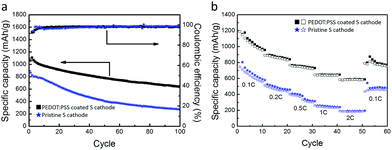 | ||
| Fig. 5 Comparison in (a) cycling stability (0.2 C) and (b) rate performance between pristine S cathode and PEDOT:PSS-coated S cathode. | ||
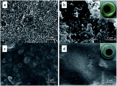
The significant improvement in the electrochemical performance confirms the “trap and reutilization” effect of the PEDOT:PSS film (Fig. 1). For the pristine S cathode, during the repeated lithiation–delithiation process, the dissolved polysulfides may mostly transfer between cathode and anode (Fig. 1a), leading to shuttle effect, active material loss and capacity decay. After coating, the PEDOT:PSS film serves as a soft buffer to restrict the diffusion of polysufides into the electrolyte, so the shuttle effect can be largely alleviated. Meanwhile, the trapped polysufides can be further reduced/oxidized due to the electric conductivity of PEDOT:PSS. In addition, this ductile film can also relieve the volume change and strengthen the connection between the insulated S/Li2S particles and Super-P conductor. All these factors help the PEDOT:PSS-coated S cathode to achieve a much higher discharge capacity and considerably improved cyclability. To gain insight into the protection mechanism of PEDOT:PSS coating, the morphology evolution of the electrodes before and after cycling was investigated, as shown in Fig. 6. For the pristine S electrode, clear S particles are observed in the fresh cathode (Fig. 6a), but after 50 cycles the particles greatly aggregate (Fig. 6b), implying a serious redistribution of active materials upon cycling. For the PEDOT:PSS-coated S cathode, it still keeps a smooth and dense surface after 50 cycles (Fig. 6d), which is quite similar to the fresh one (Fig. 6c). The “trap” effect of PEDOT:PSS can be also visually proved by checking the disassembled cells after 100 cycles (the insets of Fig. 6b and d). The inside of the pristine sulfur cell became yellow in the ether electrolyte, but no color change was observed in the PEDOT:PSS-coated S cathode.
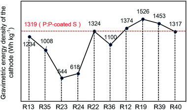
In order to provide more valuable data for practical application, the capacity density and energy density were calculated based on the total composition of sulfur cathode and the corresponding lithium–sulfur batteries with the model proposed by Gao et al.28 For the purpose of simplicity, only the mass and volume of active material, carbon, binder and conductive polymer were considered. The detailed calculation process is described in the ESI.† The energy densities of the typical LiCoO2 cathode and LiCoO2–graphite battery were also calculated based on the same model to get a quick understanding of the general situation. As shown in Fig. 7a, the PEDOT:PSS-coated S cathode displays a gravimetric energy density of 1319 W h kg−1, much higher than that of the pristine S cathode (1004 W h kg−1) and the LiCoO2 cathode (521 W h kg−1). When it couples with lithium anode, the corresponding battery demonstrates gravimetric energy densities of 1113 W h kg−1, much higher than those of the traditional LiCoO2–graphite battery (362 W h kg−1). But, the lithium–sulfur system does not show advantage in the volumetric energy density, the PEDOT:PSS-coated S cathode displays a volumetric energy density of 739 W h L−1, which is much lower than that of the LiCoO2 cathode (1669 W h L−1). When coupled with lithium anode, the gap narrowed, but the volumetric energy density is still lower than that of the LiCoO2–graphite battery. Obviously, the main advantage of lithium–sulfur system is its high gravimetric energy density. Fig. 8 and Table S1† also give a rough comparison of specific capacity and energy density (calculated based on the overall cathode) between the PEDOT:PSS-coated S cathode and some typical nano-architectured sulfur-based composite cathodes (based on mesoporous carbon,15,37 microporous carbon,25,26 graphene,24,38 hollow structured sulfur12,21 and polysulfide mediator materials39,40). Through this feasible method, the PEDOT:PSS-coated S cathode achieves a high gravimetric energy density of the cathodes (1319 W h kg−1), which is much better than the cathodes based on the micro/meso porous carbon and comparable to those of the cathodes based on graphene, hollow structured sulfur and polysulfide mediator materials.
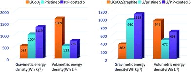 | ||
| Fig. 7 Energy densities of the pristine S cathode, the PEDOT:PSS-coated S cathode (P:P-coated S) and LiCoO2 cathode: (a) the cathodes, (b) the corresponding batteries. | ||
Conclusions
A great and repeatable improvement of electrochemical performance of lithium–sulfur battery has been achieved by coating a conductive PEDOT:PSS film on the surface of pristine sulfur electrode. Due to the “trapping and reutilization” effect of PEDOT:PSS film, the cathode delivers a specific capacity as high as 1061 mA h g−1. After 100 cycles, the PEDOT:PSS-coated S cathode can still maintain a specific discharge capacity of 638 mA h g−1, much higher than those of the pristine S cathode (275 mA h g−1). The gravimetric energy densities of the cell with the modified S cathode are estimated to 1113 W h kg−1 based on the total composition of electrode. It is noted that the polymer layer is coated on the S electrode rather than the S particles, which is meaningful for industrial operability. With this strategy, we believe that we can further improve the electrochemical performance of lithium–sulfur battery by addressing the thickness of coating layer and employing different polymer layers.Acknowledgements
This work was supported by the 973 program (Grant no. 2015CB258400), the National Science Foundation of China (Grant nos 21273087, 21271078 and 51361130151). The authors acknowledge the Analytical and Testing Center of HUST for FESEM, XPS measurements.Notes and references
- B. Scrosati, J. Hassoun and Y. K. Sun, Energy Environ. Sci., 2011, 4, 3287 CAS.
- P. G. Bruce, S. A. Freunberger, L. J. Hardwick and J. M. Tarascon, Nat. Mater., 2012, 11, 19 CrossRef CAS PubMed.
- A. Manthiram, Y. Z. Fu and Y. S. Su, Acc. Chem. Res., 2012, 10, 1125 Search PubMed.
- X. Ji and L. F. Nazar, J. Mater. Chem., 2010, 20, 9821 RSC.
- K. Junghoon, D. J. Lee, H. G. Jung, Y. K. Sun, J. Hassoun and B. Scrosati, Adv. Funct. Mater., 2013, 23, 1076 CrossRef PubMed.
- L. Chen and L. L. Shaw, J. Power Sources, 2014, 267, 770 CrossRef CAS PubMed.
- V. S. Kolosnitsyn and E. V. Karaseva, Russ. J. Electrochem., 2008, 44, 506 CrossRef CAS.
- C. Wang, W. Wan, J. T. Chen, H. H. Zhou, X. X. Zhang, L. X. Yuan and Y. H. Huang, J. Mater. Chem. A, 2013, 1, 1716 CAS.
- G. Zheng, Y. Yang, J. J. Cha, S. S. Hong and Y. Cui, Nano Lett., 2011, 11, 4462 CrossRef CAS PubMed.
- Z. W. Seh, W. Li, J. J. Cha, G. Zheng, Y. Yang, M. T. McDowell, P. C. Hsu and Y. Cui, Nat. Commun., 2012, 4, 1331 CrossRef PubMed.
- W. Li, Q. Zhang, G. Zheng, Z. W. Seh, H. Yao and Y. Cui, Nano Lett., 2013, 13, 5534 CrossRef CAS PubMed.
- W. Zhou, Y. Yu, H. Chen, F. J. DiSalvo and H. D. Abruna, J. Am. Chem. Soc., 2013, 135, 16736 CrossRef CAS PubMed.
- X. Zhang, W. Wang, A. Wang, Y. Huang, K. Yuan, Z. Yu, J. Qiu and Y. Yang, J. Mater. Chem. A, 2014, 2, 11660 CAS.
- G. Ma, Z. Wen, Q. Wang, C. Shen, J. Jin and X. Wu, J. Mater. Chem. A, 2014, 2, 19355 CAS.
- X. Ji, K. T. Lee and L. F. Nazar, Nat. Mater., 2009, 8, 500 CrossRef CAS PubMed.
- J. Schuster, G. He, B. Mandlmeier, T. Yim, K. T. Lee, T. Bein and L. F. Nazar, Angew. Chem., Int. Ed., 2012, 51, 3591 CrossRef CAS PubMed.
- Z. Li, L. Yuan, Z. Yi, Y. Liu, Y. Xin, Z. Zhao and Y. Huang, Nanoscale, 2014, 6, 1653 RSC.
- J. Jin, Z. Wen, G. Ma, Y. Lu, Y. Cui, M. Wu, X. Liang and X. Wu, RSC Adv., 2013, 3, 2558 RSC.
- B. Zhang, X. Qin, G. R. Li and X. P. Gao, Energy Environ. Sci., 2010, 3, 1531 CAS.
- L. Ji, M. Rao, S. Aloni, L. Wang, E. J. Cairns and Y. Zhang, Energy Environ. Sci., 2011, 4, 5053 CAS.
- W. Li, G. Zheng, Y. Yang, Z. W. Seh, N. Liu and Y. Cui, Proc. Natl. Acad. Sci. U. S. A., 2013, 110, 7148 CrossRef CAS PubMed.
- S. Chen, X. Huang, H. Liu, B. Sun, W. Yeoh, K. Li, J. Zhang and G. Wang, Adv. Energy Mater., 2014, 4, 1301761 Search PubMed.
- G. Zheng, Q. Zhang, J. J. Cha, Y. Yang, W. Li, Z. W. Seh and Y. Cui, Nano Lett., 2013, 13, 1265 CrossRef CAS PubMed.
- X. Huang, B. Sun, K. Li, S. Chen and G. Wang, J. Mater. Chem. A, 2013, 1, 13484 CAS.
- Z. Li, L. Yuan, Z. Yi, Y. Sun, L. Liu, Y. Jiang, Y. Shen, Y. Xin, Z. Zhang and Y. Huang, Adv. Energy Mater., 2014, 4, 1301473 Search PubMed.
- D. W. Wang, G. Zhou, F. Li, K. H. Wu, G. Q. Lu, H. M. Cheng and I. R. Gentle, Phys. Chem. Chem. Phys., 2012, 14, 8703 RSC.
- S. Xin, L. Gu, N. H. Zhao, Y. X. Yin, L. J. Zhou, Y. G. Guo and L. J. Wan, J. Am. Chem. Soc., 2012, 134, 18510 CrossRef CAS PubMed.
- J. Gao and H. D. Abruña, J. Phys. Chem. Lett., 2014, 5, 882 CrossRef CAS.
- Z. Dong, J. Zhang, X. Zhao, J. Tu, Q. Su and G. Du, RSC Adv., 2013, 3, 24914 RSC.
- L. Xiao, Y. Cao, J. Xiao, B. Schwenzer, M. H. Engelhard, L. V. Saraf, Z. Nie, G. J. Exarhos and J. Liu, Adv. Mater., 2012, 24, 1176 CrossRef CAS PubMed.
- G. Ma, Z. Wen, J. Jin, Y. Lu, X. Wu, C. Liu and C. Chen, RSC Adv., 2014, 4, 21612 RSC.
- F. Wu, J. Chen, R. Chen, S. Wu, L. Li, S. Chen and T. Zhao, J. Phys. Chem. C, 2011, 115, 6057 CAS.
- J. Shao, X. Li, L. Zhang, Q. Qu and H. Zheng, Nanoscale, 2013, 5, 1460 RSC.
- G. C. Li, G. R. Li, S. H. Ye and X. P. Gao, Adv. Energy Mater., 2012, 2, 1238 CrossRef CAS PubMed.
- L. X. Miao, W. K. Wang, A. B. Wang, K. G. Yuan and Y. S. Yang, J. Mater. Chem. A, 2013, 1, 11659 CAS.
- Y. Yang, G. Yu, J. J. Cha, H. Wu, M. Vosgueritchian, Y. Yao, Z. Bao and Y. Cui, ACS Nano, 2011, 5, 9187 CrossRef CAS PubMed.
- X. Tao, X. Chen, Y. Xia, H. Huang, Y. Gan, R. Wu, F. Chen and W. Zhang, J. Mater. Chem. A, 2013, 1, 3295 CAS.
- B. Ding, C. Yuan, L. Shen, G. Xu, P. Nie, Q. Lai and X. Zhang, J. Mater. Chem. A, 2013, 1, 1096 CAS.
- Q. Pang, D. Kundu, M. Cuisinier and L. F. Nazar, Nat. Commun., 2014, 5, 4759 CrossRef CAS PubMed.
- X. Liang, C. Hart, Q. Pang, A. Garsuch, T. Weiss and L. F. Nazar, Nat. Commun., 2015, 6, 5682 CrossRef PubMed.
Footnote |
| † Electronic supplementary information (ESI) available. See DOI: 10.1039/c5ra05481h |
| This journal is © The Royal Society of Chemistry 2015 |

