 Open Access Article
Advancement of sorption-based heat transformation by a metal coating of highly-stable, hydrophilic aluminium fumarate MOF†
Felix Jeremiasab,
Dominik Fröhlichab,
Christoph Janiak*a and
Stefan K. Henninger*b
aInstitut für Anorganische Chemie und Strukturchemie, Universität Düsseldorf, 40204 Düsseldorf, Germany. E-mail: janiak@uni-duesseldorf.de
bDepartment of Thermally Active Materials and Solar Cooling, Fraunhofer Institute for Solar Energy Systems (ISE), Heidenhofstr. 2, 79110 Freiburg, Germany
First published on 13th May 2014
Abstract
The distinctive water sorption properties of microporous aluminium fumarate (s-shaped isotherm, narrow hysteresis, loading >0.3 g g−1 at a relative pressure as low as p/p0 = 0.3 under realistic working conditions) permit a large advancement of MOF-based sorption heat transformation processes, especially as we demonstrate that the favourable sorption properties are accompanied by an unprecedented cyclic hydrothermal stability. With regard to the application of heat transformation, where unhindered heat and mass transfer are crucial for fast ad-/desorption cycles and a high power density, the question of proper shaping was also addressed. A 300 μm thick, polycrystalline, thermally well coupled and highly accessible coating of microporous aluminium fumarate was deposited on a metal substrate via the thermal gradient approach, and found to be stable for the first 4500 ad-/desorption cycles with water vapour.
1 Introduction
Metal–organic frameworks (MOFs) receive continuous attention due to their unsurpassed porosity and chemical variability, which both originate from the inherent, molecular cluster-linker concept.1 Substantial progress can be expected from their introduction into the fields of gas storage,2,3 gas4 and liquid5 separation processes, drug delivery,6 heterogeneous catalysis7 and other applications,8 but especially for sorption-based heat transformation purposes.Thermally driven adsorption chillers (TDCs) or adsorption heat pumps (AHPs) pose an alternative to traditional air conditioners, heat pumps or condensing boilers operating on electricity or fossil fuels. Driven by solar or waste heat, TDCs/AHPs can help to minimize primary energy consumption. They are based on the evaporation of coolants, preferably water, and consecutive adsorption at a microporous material under specific conditions.
This technology has gained more and more interest during the last years, because it allows waste heat, which would otherwise be simply released to the environment, to be used for cooling applications, or stored, e.g., for heating in winter. Additionally, the process can be operated in heat-pump mode: as additional thermal energy from the environment can be used for heating, less fuel is required.9–11 It is clear that the performance, efficiency and range of use of a sorption-based heat pump, or chiller, drastically depend on the performance of the applied sorption material. MOFs are of high interest for the use as adsorbents, as they can surpass classical materials like silica gels or zeolites in terms of fluid uptake capacity and also offer the potential for tuning the microporosity and hydrophilicity through their variable building blocks depending on the specific heat transformation application. MOFs are being increasingly investigated for this purpose because of their high porosities, tunable hydrophilicities, and inherent, narrow pore size distributions which result in a sharp loading step. However, low hydrophilicity, insufficient hydrothermal stability and a pricey production still impede their commercial success in this and related fields.9,12–18
While the chemical properties of a MOF material can be tailored to meet the specifications of a particular task,19 harsh environmental conditions and especially the presence of water vapour often result in irreversible structural transformations and rapid loss of porosity especially in well-established and examined materials: copper trimesate HKUST-1 (although it is synthesized in aqueous solution), zinc terephthalate MOF-5, and even zirconium aminoterephthalate H2N-UiO-66 show framework disintegration under humid working conditions.15,20,21 The decomposition process has been found to commence at the metal-linker coordination bond in most cases.21 The collection of better water-stable MOFs includes many zeolitic imidazolate frameworks (ZIFs)22 and a few other azolate-derived compounds,16,23 MOFs based on Cr(III) (such as MIL-101),14 or use 4th group metal clusters,15,24 some MOFs that employ phosphonates as linkers,25 and so on. However, hydrothermal stability is often achieved by hydrophobicity, which can easily be deduced from the comparatively late rise of the water sorption isotherm. This is the case, e.g., for many ZIFs, metal azolate–carboxylate MOFs,26 and to some extent also MIL-101.
Suitable equilibrium sorption characteristics are a necessary requirement for any MOF application, but when it comes to fast, cyclic adsorption processes, unhindered heat and mass transfer have to be ensured as well. Hence, the MOF cannot be used as a powder, but must be fabricated into a device. While elaborate procedures are available for the production of custom-made, yet low-capacity μm-films, e.g., by means of direct or seeded growth,27 electrochemical synthesis,28 microwave-induced29 or self-assembled monolayer (SAM-) assisted deposition,30 results are scarce when it comes to high-capacity, sturdy, firmly adhering films or membranes which are at the same time highly accessible and thermally well coupled to the substrate. Such films are necessary for high-turnover applications in the field of gas sorption, catalysis etc., where substantial amounts of heat have to be delivered or dissipated, with sorption-based heat transformation being an especially challenging task for the material because of the recurring ad- and desorption cycles (Fig. 1).
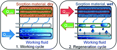 | ||
| Fig. 1 Working principle of a sorption heat pump/chiller. (1) Working cycle: a working fluid (typically H2O due to the high evaporation enthalpy of 44 kJ mol−1) is evaporated at low pressure by application of evaporation heat Qevap, and adsorbed at a microporous material, releasing adsorption heat Qads. (2) Regeneration cycle: when the adsorbent is saturated, driving heat Qdes is applied for desorption of the working fluid. The vapour then condenses at a cooler, and condensation heat Qdes is released. Energy is now stored until reinitiation of the working cycle. Note: low temperature (T) heat is depicted in blue, medium T heat in green and high T heat in red. Copyright by the Royal Society of Chemistry, reproduced by permission of the authors of ref. 13. | ||
Microporous aluminium fumarate (abbreviated as μp-AF in this publication) keeps appearing in the patent literature since 2007,31,32 and it distinguishes from other MOFs especially by the fact that it can be easily prepared from inexpensive reagents via a water-based precipitation approach. This also means that at least some water stability can be anticipated. Gas separation, H2 or methane storage, and storage and release of liquid agents have been named as possible applications for μp-AF, for which it may be marketed by BASF as Basolite™ A520.31,33 These facts all point out that μp-AF can become one of the commercially most important MOFs, but, curiously enough, publications in scientific journals remain scarce.33,34
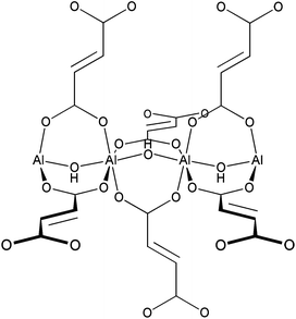
Structurally, μp-AF resembles MIL-53, as it also consists of infinite Al–OH–Al chains connected by fumarate linkers (Scheme 1).35 From this comparison, a 3D structure consisting of [Al(OH)(O2C–CH![[double bond, length as m-dash]](https://www.rsc.org/images/entities/char_e001.gif) CH–CO2)] with rhombohedral channels is probably formed (see Fig. S8 in ESI†).31
CH–CO2)] with rhombohedral channels is probably formed (see Fig. S8 in ESI†).31
Here, a MOF-based material with promising properties (capacity, sorption behaviour, multi-cycle stability), and also a method for the production of a coating on a metallic substrate are presented. In this contribution, we demonstrate the unprecedented water-stability and hydrophilicity of μp-AF and fabricate this MOF into a thermally well coupled coating on aluminium metal sheets, e.g., for use on heat exchangers in sorption-based heat transformation applications.
2 Experimental
2.1 Synthesis of bulk-μp-AF
Although a convenient water-based precipitation approach for the synthesis of microporous aluminium fumarate, μp-AF is known, a different patent procedure using dimethyl formamide as the solvent was chosen because of the alleged better reaction control, and adaptability towards the fabrication of MOF coatings.31 In a 1000 mL round bottom flask, 26.9 g (108 mmol) of aluminium chloride hexahydrate (p.a., Merck) and 15.4 g (133 mmol) of fumaric acid (≥99.5%, Carl Roth) were dissolved in 550 mL of freshly distilled dimethyl formamide (≥99.5%, Carl Roth). The turbid, yellowish mixture was stirred at 130 °C for 4 days. After cooling, the snow-white precipitate was filtered off and stirred twice in redist. acetone (1 h and 24 h, 200 mL each), and twice in redist. ethanol (1 h and 24 h, 200 mL each). The solid was then dried in air at 80 °C. Yield: 15.4 g (90% based on Al). IR, neat (ATR), 3385, 1593, 1471, 1419, 1212, 1152, 1005, 985, 804, 713, 694, 646, 483 cm−1 (see Fig. S4†). C4H3O5Al (158.04) calc. C 30.40, H 1.91%; found C 30.91, H 2.82.2.2 Thermal gradient coating
2.3 Analytics: procedure and instrumentation
N2 adsorption isotherms were obtained on a Quantachrome® Nova @ 77 K, after vac. degassing (120 °C/24 h). H2O adsorption isotherms: obtained on a Quantachrome® Hydrosorb, after vac. degassing (120 °C/24 h). H2O adsorption isobars and powder cycle stability were examined in a Setaram™ TGA-DSC-111. A humidified argon gas flow (40 °C, 76.3% relative humidity) was generated by a Setaram™ WetSys humidity controller and passed through the sample chamber, while the temperature of the sample chamber itself was varied. For multi-cycle ad-/desorption experiments, the temperature of the sample chamber was varied between 40 °C and 140 °C with a cycle time of 5 h. X-ray diffractograms were acquired on a Bruker D8 Advance with DaVinci™, using a Cu anode tube at 40 kV/40 mA, with a Ni filter and constant sample illumination spot size (broadness: 12 mm); step size 0.02°, 1.0 s per step, Cu-Kα radiation. A rotating sample holder was used for powders. A MRI humidity chamber was used for controlled humidity experiments (Fig. 2d), where a humidified N2 gas flow was passed over the sample at atmospheric pressure. Before each scan, the sample was allowed to equilibrate for 90 min. A Newport stage with three axes was used for coated sheets. IR spectra were obtained on a PerkinElmer™ SpectrumTwo FTIR equipped with a diamond ATR unit. Multi-cycle stability tests of coated samples: in order to investigate the adsorption/desorption cycle stability of μp-AF over 1500 and another 3000 adsorption/desorption cycles, multi-cycle experiments were conducted in a special apparatus under pure water vapour atmosphere (1300 Pa), where the samples were clamped to a heating/cooling plate, with the temperature alternating between 125 °C and 20 °C for 90 seconds each. Hence, relative vapour pressure values of p/p0 = 0.006 or, respectively, p/p0 = 0.55, are generated and the main loading lift of μp-AF is covered. Microscopic images were obtained on a Keyence® VHX reflected-light microscope. Scanning electron microscope images were obtained on a FEI™ QUANTA 400 MK-II (25 kV, ET-detector). Heat capacity of bulk aluminium fumarate was determined using a SETARAM™ SenSys evo DSC calorimeter. Heat conductivity and contact resistance were obtained on a NETZSCH LFA 457 laser flash analysis apparatus under vacuum. For the investigation of bulk aluminium fumarate, a pellet (Ø = 12.7 mm, forming pressure = 13 kN) was prepared. For investigation of the coating, a 10 × 10 mm2 cut was used. Samples were coated with graphite on both sides and dehumidified at 120 °C prior to measurement. A Cowan 2-layer approach with regard to heat loss and pulse correction was applied. Heat capacity and thermal conductivity of the Al substrate were obtained from the Netzsch database, the heat capacity of the coating was calculated from the regression function given in the ESI.† For each temperature step, three values were taken, the given values are calculated as the arithmetic average. The calculation of the thermal conductivity was performed using the Netzsch software algorithm, which is based on the work by Hartmann et al.36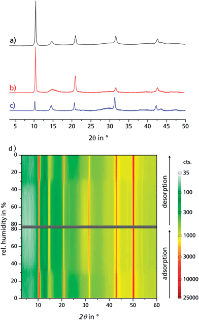 | ||
| Fig. 2 PXRD of bulk μp-AF as extracted from patent literature (a), dried μp-AF (stored at 120 °C under vacuum for 24 h (b)) and hydrated μp-AF (stored under 100% water vapour atmosphere overnight, (c)). (d) Reversible structural transition observed by in situ PXRD in a humidity chamber at 313 K. See Fig. S5 in the ESI† for the individual diffractograms. | ||
3 Results and discussion
3.1 Bulk μP-AF
Aluminium chloride hexahydrate reacts with fumaric acid in dimethyl formamide (DMF) at 130 °C under formation of aluminium fumarate, [Al(OH)(O2C–CH![[double bond, length as m-dash]](https://www.rsc.org/images/entities/char_e001.gif) CH–CO2)] in high yield. The product was verified by positively matching the powder X-ray diffractograms of both dried and rehydrated μp AF with the pattern given for genuine Basolite™ A520 in the literature (Fig. 2a–c).31
CH–CO2)] in high yield. The product was verified by positively matching the powder X-ray diffractograms of both dried and rehydrated μp AF with the pattern given for genuine Basolite™ A520 in the literature (Fig. 2a–c).31
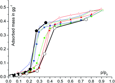
Water adsorption isotherms were acquired in a temperature range between 298 K and 333 K, leading to a maximum water vapour uptake of approx. 0.45 g g−1. The isotherms show a very favorable s-shape, with a steep increase in a narrow pressure range (p/p0 = 0.2–0.3) (Fig. 3). The desorption hysteresis is small compared to other, comparably hydrophilic MOFs like iron or aluminium trimesate, MIL-100 (Fe, Al)13 or zirconium aminoterephthalate H2N-UiO-66.15 The H2O loading of 0.45 g g−1 correlates well to the micropore volume of 0.48 cm3 g−1 determined from N2 sorption experiments for a solvent of density 1 g cm−3, so that the micropores are filled at high p/p0. This points to a high uniformity and hydrophilicity of the inner pore surface, without particularly hydrophobic sites. However, the conditions inside a thermally driven chiller can be considered to be isobaric rather than isothermal, due to the cyclic heating and cooling process. With the intent to simulate conditions close to reality, adsorption isobars were acquired at a partial water vapour pressure of 1.2 kPa (corresponding to an evaporator temperature of 10 °C), while desorption was examined at 5.6 kPa (corresponding to a condenser temperature of 35 °C) (see Fig. 3). During adsorption, the main loading lift of μp-AF occurs at p/p0 < 0.3, permitting a medium temperature level of approx. 30 °C. The main desorption step occurs already between a relative pressure range of 0.4 > p/p0 > 0.25, corresponding to a desorption (“driving”) temperature of as low as 65 °C – a level which can be easily produced from solar or (surplus) district heat. These properties fit excellently to the demands typically anticipated for a thermally driven chiller.12,37 From in situ ad-/desorption PXRD analysis of μp-AF (Fig. 2d and S5 in ESI†), we could find evidence that the structure is reversibly deformed during the transition. Based on the structural analogy between μp-AF (Basolite™ A520) and MIL-53, the aluminium fumarate framework can also be assumed to be a flexible, ‘breathing’-type network adapting to guest molecules, that is, it can assume different shapes and porosities depending on the guest's presence or absence.35,38 In the case of water as a guest molecule, however, the observed structural change in μp-AF was minor (see Fig. 2).
 | (1) |
 | (2) |
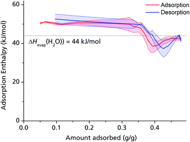
The adsorption enthalpy for a specific amount of adsorbate can now be calculated from a dataset of different temperatures T1, T2, …, Tn, required to obtain adsorption of this amount, and the corresponding absolute pressures p1, p2, …, pn, as the points Pn(ln(pn/p0)|1/Tn) will describe a straight line with the slope −ΔHads/R. Values between isotherm data points were interpolated by straight lines, and ΔHads was calculated over the whole adsorption range (Fig. 4).
For the largest part of the adsorbed amount, the differential adsorption enthalpy ΔHads remains constantly about 10% above the evaporation enthalpy of water, which is a value in the range typically found for medium hydrophilic zeolites or silica gels.11,40 This points to a uniform, comparatively hydrophilic internal surface, with water molecules accumulating homogeneously along the channel walls. This behaviour differs considerably from that of, e.g., MIL-100 or MIL-101, where strong coordinative bonds are established between the first adsorbed H2O molecules and the highly polar, hydrophilic metal ion clusters,13 but makes sense given that μP-AF does not contain metal ion clusters, but infinite Al–O–Al–O chains running along the channel walls.
ΔHads drops substantially below the evaporation enthalpy of water when the pores are almost completely filled, which means that a simultaneous, endothermic process must take place at this point, such as the reversible deformation of the framework that can be deducted from the in situ PXRD measurements (Fig. 2). Another possible endothermic process, which may be responsible for the drop of adsorption enthalpy at high adsorbed amounts, which is not easy to detect, is the rearrangement of already adsorbed water molecules towards a closer, yet energetically less favourable configuration upon pore filling.
For the pressed pellet, the thermal conductivity in this temperature range lies around 0.12 W m−1 K−1.
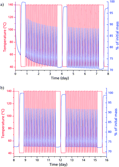
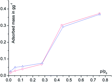
Judged from the longer analysis cycles during the multi-cycle ad-/desorption experiments in Fig. 5, the adsorption capacity remains within the range to be expected from the volumetric measurements: 0.37 g g−1 after 20, 0.38 g g−1 after 40, 0.37 g g−1 after 60 and 0.37 g g−1 after 80 cycles. While the framework seems to lose approx. 6% of its weight during the first 20 cycles, this seems to have no impact on the sorption capacity itself. The decrease in dry mass indicates a further activation effect due to water sorption cycles. This post-activation phenomenon can be explained by stepwise removing of fumaric acid, which apparently could not be fully cleaved from the narrow and highly polar channels of μp-AF by the initial washing procedure. During cycling however, the desorbing water vapour is likely to entrain the high-boiling, yet poorly water-soluble fumaric acid in a way similar to steam distillation.
3.2 μp-AF@Al coating
Replacement of the Al3+-source. As chloride anions are known to provoke corrosion of the most common metallic substrates, e.g., copper, aluminium, and also stainless steel alloys, the aluminium chloride used in the original synthesis procedure31 was replaced by an equimolar amount of aluminium nitrate nonahydrate.
Increase of reactant concentration. In order to speed up layer growth and obtain sufficiently thick layers, we doubled the concentrations of reactants (aluminium nitrate nonahydrate and fumaric acid) for a second run, compared to the original procedure.
Protective lacquer. For increased mechanical stability, one sample was additionally furnished with a protective lacquer. An industry-standard, highly water vapour permeable silicone-resin varnish was chosen for this purpose (Evonik Silikophen® P50/300).
Reaction temperature. We found that it was necessary to set the temperature of the substrate to 145 °C compared to 130 °C for the batch synthesis in order to obtain an evenly distributed coating. The temperature of the cooling jacket was set to 30 °C.
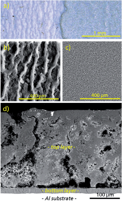
Under the conditions given above, a uniform coating of μp-AF could be deposited on pretreated aluminium sheets (Fig. 6 and 7). As can be seen from the polished cross-section (see Fig. 7d), the coating consists of a macroporous and structured top layer with a thickness of approx. 280 μm (top-down view in Fig. 7b). Applying moderate force, the top layer can be removed with a spatula, exposing a denser and firmly adhering bottom layer with a thickness of only 20 μm (Fig. 7c). Both layers consist of crystalline μp-AF, as proven by PXRD (see Fig. S6 in ESI†).
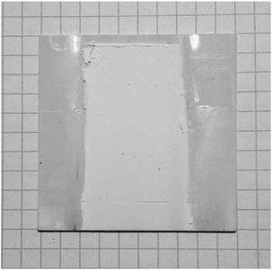 | ||
| Fig. 6 Representative image of an μp-AF@Al coated aluminium sheet. Edges were covered by mounting clamps during coating synthesis. | ||
The gravimetric density of the μp-AF coating (determined by measuring and weighing a flake removed from the substrate) is ρcoating = 0.61 g cm−3.
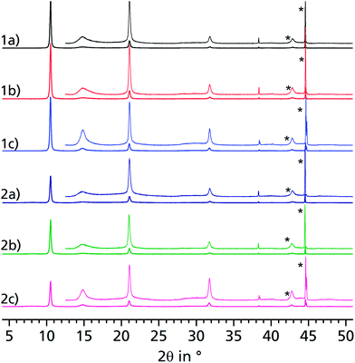
When comparing the diffractograms of the coated sheets before cycling, after 1500 and after 4500 cycles, no weakening or broadening of the reflections can be seen in both cases. In fact, the intensity and sharpness of the reflections at 2θ = 14.9° and 31.8° increases. This can be explained by recrystallization/rearrangement phenomena during cycling, and also by a post-activation procedure as described above for bulk μp-AF.
After 1500 and 4500 cycles, the desorption isobar for the μp-AF coating in Fig. 9 corresponds well to the isobar acquired for bulk μp-AF (Fig. 3). Also, the H2O capacity of 0.37 g g−1 from the desorption isobar corresponds to the equilibrium loading in the multi-cycle experiments of bulk μp-AF (Fig. 5). This is an excellent water uptake value as to the best of our knowledge, so far, no other MOF has shown such a stability towards the first 4500 ad/desorption cycles with water vapor (cf. Fig. 8).
Sheet 2 was additionally covered with silicone resin and features the same shape of the isotherm after 4500 cycles, but with a smaller relative load, due to the additional weight added to the coating by the silicone resin (see Fig. S7 in ESI†).
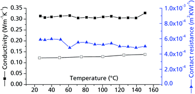 | ||
| Fig. 10 Thermal conductivity of μp-AF. Measurements were conducted on bulk μp-AF (pellet, Ø = 12.68 mm, h = 1.71 mm, forming pressure = 13 kN; ρ = 0.714 g cm−3, empty symbols) and a μp-AF@Al coated sheet with protective layer (filled symbols). For the cp values, the curve determined for bulk μp-AF was used in both cases (see Fig. S3 in ESI†). | ||
The contact resistance between the MOF layer and the resin coating is about 5.1 × 10⁻⁴ m2 K W−1 in the examined temperature range (Fig. 10). For comparison, this value equals the contact resistance between a similar combination of materials (activated carbon pressed to an aluminium bronze surface, but with a pressure of 1.0 MPa) and is hence a very acceptable value for a MOF–metal interface.48
4 Conclusions
The thorough investigation of the water sorption properties of μp-AF show that this remarkable MOF may be employed as a promising adsorbent for heat transformation applications. The maximum water exchange of 0.35 g g−1 is certainly lower than in other MOFs such as UiO-66 (ref. 15) or MIL-100,13 but it can be fully utilized under realistic, isobaric working conditions due to the hydrophilicity of μp-AF. The characteristic, steep s-shape of the isotherm in a relative pressure band of 0.2 < p/p0 < 0.35 has not been observed for other water-stable MOFs before. In this context, μp-AF can be compared best to modern, hydrophilic, zeotype adsorbents such as AlPO-18 or AlPO-4.40 In terms of cyclic hydrothermal stability, μp-AF surpasses other hydrophilic MOFs, even other aluminium carboxylates such as MIL-100(Al).13μp-AF can already be produced comparatively cost-efficiently via a simple precipitation reaction. This is in contrast to, e.g., the template-based AlPO-18 synthesis, or various hydro-/solvothermal synthesis routes required for other MOFs. μp-AF is also free of harmful components such as heavy metals or critical organic compounds. Aluminium salts are approved as EU food additives (E520-523), as well as several fumarates (E365-368).
The way towards the application has been cleared further by the successful preparation of a thick, thermally well coupled μp-AF coating on a metallic substrate via the thermal gradient approach, and its hydrothermal stability proven for 4500 ad-/desorption cycles, renders this material very interesting also for other applications such as catalysis or gas storage.
The chemically versatile C![[double bond, length as m-dash]](https://www.rsc.org/images/entities/char_e001.gif) C-bond of the fumarate linker can be a valuable anchor for further tailoring of μp-AF by post-synthetic modifications (for example, it might serve as a complex ligand after hydroxylation, or directly via the π-bond electrons). This topic should be investigated in the future, in order to render μp-AF more versatile also for highly specific applications.
C-bond of the fumarate linker can be a valuable anchor for further tailoring of μp-AF by post-synthetic modifications (for example, it might serve as a complex ligand after hydroxylation, or directly via the π-bond electrons). This topic should be investigated in the future, in order to render μp-AF more versatile also for highly specific applications.
Acknowledgements
Funding by the Federal German Ministry of Economics (BMWi) under grant-# 0327851A/B, and by the Fraunhofer Society under grant-# MAVO 824 704 is gratefully acknowledged. Part of this project is also funded by DFG grant Ja466/25-1 to CJ. This work is dedicated to Prof. Christel Marian on the occasion of her 60th birthday.Notes and references
- J. R. Long and O. M. Yaghi, Chem. Soc. Rev., 2009, 38, 1213–1214 RSC
; M. O'Keeffe and O. M. Yaghi, Chem. Rev., 2012, 112, 675–702 CrossRef CAS PubMed
; C. Janiak and J. K. Vieth, New J. Chem., 2010, 34, 2366–2388 RSC
.
- R. J. Kuppler, D. J. Timmons, Q.-R. Fang, J.-R. Li, T. A. Makal, M. D. Young, D. Yuan, D. Zhao, W. Zhuang and H.-C. Zhou, Coord. Chem. Rev., 2009, 253, 3042–3066 CrossRef CAS PubMed
; M. P. Suh, H. J. Park, T. K. Prasad and D. W. Lim, Chem. Rev., 2012, 112, 782–835 CrossRef PubMed
; H. Wu, Q. Gong, D. H. Olson and J. Li, Chem. Rev., 2012, 112, 836–868 CrossRef PubMed
; L. J. Murray, M. Dincă and J. R. Long, Chem. Soc. Rev., 2009, 38, 1294–1314 RSC
.
- J. A. Mason, M. Veenstra and J. R. Long, Chem. Sci., 2014, 5, 32–51 RSC
; R. Sathre and E. Masanet, RSC Adv., 2013, 3, 4964–4975 RSC
; J. Liu, P. K. Thallapally, B. P. McGrail, D. R. Bown and J. Liu, Chem. Soc. Rev., 2012, 41, 2308–2322 RSC
; H. Amrouche, B. Creton, F. Siperstein and C. Nieto-Draghi, RSC Adv., 2012, 2, 6028–6035 RSC
.
- J. R. Li, J. Sculley and H. C. Zhou, Chem. Rev., 2012, 112, 869–932 CrossRef CAS PubMed
; Z. Zhang, Y. Zhao, Q. Gong, Z. Li and J. Li, Chem. Commun., 2013, 49, 653–661 RSC
; H. B. Tanh Jeazet, C. Staudt and C. Janiak, Dalton Trans., 2012, 41, 14003–14027 RSC
; X. Y. Chen, V.-T. Hoang, D. Rodrigue and S. Kaliaguine, RSC Adv., 2013, 3, 24266–24279 RSC
; G. Férey, C. Serre, T. Devic, G. Maurin, H. Jobic, P. L. Llewellyn, G. De Weireld, A. Vimont, M. Daturi and J. S. Chang, Chem. Soc. Rev., 2011, 40, 550–562 RSC
; J.-R. Li, Y. Ma, M. C. McCarthy, J. Sculley, J. Yu, H.-K. Jeong, P. B. Balbuena and H.-C. Zhou, Coord. Chem. Rev., 2011, 255, 1791–1823 CrossRef PubMed
; N. Hara, M. Yoshimune, H. Negishi, K. Haraya, S. Hara and T. Yamaguchi, RSC Adv., 2013, 3, 14233–14236 RSC
; J. H. Yoon, D. Kim, X. Song, S. Han, J. Shin, S. B. Hong and M. Soo Lah, RSC Adv., 2012, 2, 11566–11573 RSC
; M. Fischer, F. Hoffmann and M. Fröba, RSC Adv., 2012, 2, 4382–4396 RSC
; L. Ge, A. Du, M. Hou, V. Rudolph and Z. Zhu, RSC Adv., 2012, 2, 11793–11800 RSC
.
- K. A. Cychosz and A. J. Matzger, Langmuir, 2010, 26, 17198–17202 CrossRef CAS PubMed
; Y.-X. Tan, Y.-P. He, M. Wang and J. Zhang, RSC Adv., 2014, 4, 1480–1483 RSC
.
- P. Horcajada, R. Gref, T. Baati, P. K. Allan, G. Maurin, P. Couvreur, G. Férey, R. E. Morris and C. Serre, Chem. Rev., 2012, 112, 1232–1268 CrossRef CAS PubMed
.
- J. Lee, O. K. Farha, J. Roberts, K. A. Scheidt, S. T. Nguyen and J. T. Hupp, Chem. Soc. Rev., 2009, 38, 1450–1459 RSC
; M. Yoon, R. Srirambalaji and K. Kim, Chem. Rev., 2012, 112, 1196–1231 CrossRef CAS PubMed
; M. A. Gotthardt, A. Beilmann, R. Schoch, J. Engelke and W. Kleist, RSC Adv., 2013, 3, 10676–10679 RSC
; Y. Fu, D. Sun, M. Qin, R. Huang and Z. Li, RSC Adv., 2012, 2, 3309–3314 RSC
.
- A. U. Czaja, N. Trukhan and U. Muller, Chem. Soc. Rev., 2009, 38, 1284–1293 RSC
; G. Férey, Dalton Trans., 2009, 4400–4415 RSC
; M. J. Prakash and M. S. Lah, Chem. Commun., 2009, 3326–3341 RSC
; C. Hou, Q. Xu, Y. Wang and X. Hu, RSC Adv., 2013, 3, 19820–19823 RSC
; J. F. Guo, C. M. Li, X. L. Hu, C. Z. Huang and Y. F. Li, RSC Adv., 2014, 4, 9379–9382 RSC
.
- F. Jeremias, D. Fröhlich, C. Janiak and S. K. Henninger, New J. Chem., 2014, 38, 1846–1852 RSC
; C. Janiak and S. K. Henninger, Nachr. Chem., 2013, 61, 520–523 CrossRef CAS
.
- Y. I. Aristov, Appl. Therm. Eng., 2013, 50, 1610–1618 CrossRef CAS PubMed
; R. Wang and R. Oliveira, Prog. Energy Combust. Sci., 2006, 32, 424–458 CrossRef PubMed
; Y. I. Aristov, Int. J. Refrig., 2009, 32, 675–686 CrossRef PubMed
; L. G. Gordeeva, A. Freni, Y. I. Aristov and G. Restuccia, Ind. Eng. Chem. Res., 2009, 48, 6197–6202 CrossRef
; Y. I. Aristov, J. Chem. Eng. Jpn., 2007, 40, 1242–1251 CrossRef
; Y. I. Aristov, M. M. Tokarev, A. Freni, I. S. Glaznev and G. Restuccia, Microporous Mesoporous Mater., 2006, 96, 65–71 CrossRef PubMed
; Y. I. Aristov, B. Dawoud, I. S. Glaznev and A. Elyas, Int. J. Heat Mass Transfer, 2008, 51, 4966–4972 CrossRef PubMed
; Y. I. Aristov, G. Restuccia, G. Cacciola and V. N. Parmon, Appl. Therm. Eng., 2002, 22, 191–204 CrossRef
.
- N. C. Srivastava and I. W. Eames, Appl. Therm. Eng., 1998, 18, 707–714 CrossRef CAS
.
- S. K. Henninger, F. Jeremias, H. Kummer and C. Janiak, Eur. J. Inorg. Chem., 2012, 2625–2634 CrossRef CAS
.
- F. Jeremias, A. Khutia, S. K. Henninger and C. Janiak, J. Mater. Chem., 2012, 22, 10148–10151 RSC
.
- J. Ehrenmann, S. K. Henninger and C. Janiak, Eur. J. Inorg. Chem., 2011, 471–474 CrossRef CAS
.
- F. Jeremias, V. Lozan, S. Henninger and C. Janiak, Dalton Trans., 2013, 42, 15967–15973 RSC
.
- S. K. Henninger, H. A. Habib and C. Janiak, J. Am. Chem. Soc., 2009, 131, 2776–2777 CrossRef CAS PubMed
.
- F. Jeremias, S. K. Henninger and C. Janiak, Chem. Commun., 2012, 48, 9708–9710 RSC
.
- A. Rezk, R. Al-Dadah, S. Mahmoud and A. Elsayed, Int. J. Heat Mass Transfer, 2012, 55, 7366–7374 CrossRef CAS PubMed
.
- A. Khutia, H. U. Rammelberg, T. Schmidt, S. Henninger and C. Janiak, Chem. Mater., 2013, 25, 790–798 CrossRef CAS
; H. Jasuja, J. Zang, D. S. Sholl and K. S. Walton, J. Phys. Chem. C, 2012, 116, 23526–23532 Search PubMed
; S. M. Cohen, Chem. Rev., 2012, 112, 970–1000 CrossRef PubMed
; G. Akiyama, R. Matsuda, H. Sato, A. Hori, M. Takata and S. Kitagawa, Microporous Mesoporous Mater., 2012, 157, 89–93 CrossRef PubMed
.
- P. Küsgens, M. Rose, I. Senkovska, H. Fröde, A. Henschel, S. Siegle and S. Kaskel, Microporous Mesoporous Mater., 2009, 120, 325–330 CrossRef PubMed
.
- M. Taddei, A. Ienco, F. Costantino and A. Guern, RSC Adv., 2013, 3, 26177–26183 RSC
; J. J. Low, A. I. Benin, P. Jakubczak, J. F. Abrahamian, S. A. Faheem and R. R. Willis, J. Am. Chem. Soc., 2009, 131, 15834–15842 CrossRef CAS PubMed
.
- K. S. Park, Z. Ni, A. P. Cote, J. Y. Choi, R. Huang, F. J. Uribe-Romo, H. K. Chae, M. O'Keeffe and O. M. Yaghi, Proc. Natl. Acad. Sci. U. S. A., 2006, 103, 10186–10191 CrossRef CAS PubMed
.
- A. Demessence, D. M. D'Alessandro, M. L. Foo and J. R. Long, J. Am. Chem. Soc., 2009, 131, 8784–8786 CrossRef CAS PubMed
.
- J. H. Cavka, S. Jakobsen, U. Olsbye, N. Guillou, C. Lamberti, S. Bordiga and K. P. Lillerud, J. Am. Chem. Soc., 2008, 130, 13850–13851 CrossRef PubMed
; C. Gomes Silva, I. Luz, F. X. Llabres i Xamena, A. Corma and H. Garcia, Chem.–Eur. J., 2010, 16, 11133–11138 CrossRef PubMed
; D. Feng, Z.-Y. Gu, J.-R. Li, H.-L. Jiang, Z. Wei and H.-C. Zhou, Angew. Chem., 2012, 124, 10453–10456 CrossRef
.
- J. M. Taylor, R. K. Mah, I. L. Moudrakovski, C. I. Ratcliffe, R. Vaidhyanathan and G. K. Shimizu, J. Am. Chem. Soc., 2010, 132, 14055–14057 CrossRef CAS PubMed
; C. Serre, N. Stock, T. Bein and G. Férey, Inorg. Chem., 2004, 43, 3159–3163 CrossRef PubMed
.
- V. Colombo, C. Montoro, A. Maspero, G. Palmisano, N. Masciocchi, S. Galli, E. Barea and J. A. Navarro, J. Am. Chem. Soc., 2012, 134, 12830–12843 CrossRef CAS PubMed
.
- J. Liu, F. Sun, F. Zhang, Z. Wang, R. Zhang, C. Wang and S. Qiu, J. Mater. Chem., 2011, 21, 3775 RSC
; S. Kayaert, S. Bajpe, K. Masschaele, E. Breynaert, C. E. A. Kirschhock and J. A. Martens, Thin Solid Films, 2011, 519, 5437–5440 CrossRef CAS PubMed
; P. Falcaro, A. J. Hill, K. M. Nairn, J. Jasieniak, J. I. Mardel, T. J. Bastow, S. C. Mayo, M. Gimona, D. Gomez, H. J. Whitfield, R. Ricco, A. Patelli, B. Marmiroli, H. Amenitsch, T. Colson, L. Villanova and D. Buso, Nat. Commun., 2011, 2, 237 CrossRef PubMed
; A. Schoedel, C. Scherb and T. Bein, Angew. Chem., Int. Ed., 2010, 49, 7225–7228 CrossRef PubMed
; V. V. Guerrero, Y. Yoo, M. C. McCarthy and H.-K. Jeong, J. Mater. Chem., 2010, 20, 3938 RSC
; A. Centrone, Y. Yang, S. Speakman, L. Bromberg, G. C. Rutledge and T. A. Hatton, J. Am. Chem. Soc., 2010, 132, 15687–15691 CrossRef PubMed
; H. Guo, G. Zhu, I. J. Hewitt and S. Qiu, J. Am. Chem. Soc., 2009, 131, 1646–1647 CrossRef PubMed
; J. Gascon, S. Aguado and F. Kapteijn, Microporous Mesoporous Mater., 2008, 113, 132–138 CrossRef PubMed
.
- N. Campagnol, T. Van Assche, T. Boudewijns, J. Denayer, K. Binnemans, D. De Vos and J. Fransaer, J. Mater. Chem. A, 2013, 1, 5827 Search PubMed
; T. R. C. Van Assche, G. Desmet, R. Ameloot, D. E. De Vos, H. Terryn and J. F. M. Denayer, Microporous Mesoporous Mater., 2012, 158, 209–213 CrossRef CAS PubMed
; S. A. Silkin, V. I. Petrenko and A. I. Dikusar, Surf. Eng. Appl. Electrochem., 2010, 46, 1–8 CrossRef
; R. Ameloot, L. Pandey, M. Van der Auweraer, L. Alaerts, B. F. Sels and D. E. De Vos, Chem. Commun., 2010, 46, 3735–3737 RSC
; R. Ameloot, E. Gobechiya, H. Uji-i, J. A. Martens, J. Hofkens, L. Alaerts, B. F. Sels and D. E. De Vos, Adv. Mater., 2010, 22, 2685–2688 CrossRef PubMed
; R. Ameloot, L. Stappers, J. Fransaer, L. Alaerts, B. F. Sels and D. E. De Vos, Chem. Mater., 2009, 21, 2580–2582 CrossRef
; A. Doménech, H. García, M. T. Doménech-Carbó and F. Llabrés-i-Xamena, Electrochem. Commun., 2006, 8, 1830–1834 CrossRef PubMed
.
- Y. Yoo and H. K. Jeong, Chem. Commun., 2008, 2441–2443 RSC
.
- D. Zacher, O. Shekhah, C. Wöll and R. A. Fischer, Chem. Soc. Rev., 2009, 38, 1418–1429 RSC
; C. Scherb, R. Koehn and T. Bein, J. Mater. Chem., 2010, 20, 3046 RSC
.
- C. Kiener, U. Müller and M. Schubert, Germany Pat. WO 2007/118841 A2, 2007
.
- C. Kiener, U. Müller and M. Schubert, US Pat. 12/297,666, 2012
; E. Leung, U. Müller, N. Trukhan, H. Mattenheimer and G. Cox, US Pat. 13/249,943, 2012
.
- B. Yilmaz, N. Trukhan and U. Müller, Chin. J. Catal., 2012, 33, 3–10 CrossRef CAS
.
- M. Gaab, N. Trukhan, S. Maurer, R. Gummaraju and U. Müller, Microporous Mesoporous Mater., 2012, 157, 131–136 CrossRef CAS PubMed
.
- T. Loiseau, C. Serre, C. Huguenard, G. Fink, F. Taulelle, M. Henry, T. Bataille and G. Férey, Chem.–Eur. J., 2004, 10, 1373–1382 CrossRef CAS PubMed
; C. Serre, F. Millange, C. Thouvenot, M. Noguès, G. Marsolier, D. Louër and G. Férey, J. Am. Chem. Soc., 2002, 124, 13519–13526 CrossRef PubMed
.
- G. Langer, J. Hartmann and M. Reichling, Rev. Sci. Instrum., 1997, 68, 1510 CrossRef CAS PubMed
.
- Y. I. Aristov, Appl. Therm. Eng., 2012, 42, 18–24 CrossRef CAS PubMed
; B. B. Saha, A. Chakraborty, S. Koyama, K. Srinivasan, K. C. Ng, T. Kashiwagi and P. Dutta, Appl. Phys. Lett., 2007, 91, 111902 CrossRef PubMed
.
- J. Liu, F. Zhang, X. Zou, G. Yu, N. Zhao, S. Fan and G. Zhu, Chem. Commun., 2013, 49, 7430–7432 RSC
.
- J. Rouquerol, F. Rouquerol and K. S. W. Sing, Adsorption by Powders and Porous Solids, Academic Press, San Diego, 1998 Search PubMed
.
- S. K. Henninger, F. P. Schmidt and H. M. Henning, Appl. Therm. Eng., 2010, 30, 1692–1702 CrossRef CAS PubMed
.
- B. Mu and K. S. Walton, J. Phys. Chem. C, 2011, 115, 22748–22754 CAS
.
- M. Kandiah, M. H. Nilsen, S. Usseglio, S. Jakobsen, U. Olsbye, M. Tilset, C. Larabi, E. A. Quadrelli, F. Bonino and K. P. Lillerud, Chem. Mater., 2010, 22, 6632–6640 CrossRef CAS
; V. Guillerm, F. Ragon, M. Dan-Hardi, T. Devic, M. Vishnuvarthan, B. Campo, A. Vimont, G. Clet, Q. Yang, G. Maurin, G. Férey, A. Vittadini, S. Gross and C. Serre, Angew. Chem., Int. Ed., 2012, 51, 9267–9271 CrossRef PubMed
.
- A. Van der Drift, Philips Res. Rep., 1967, 22, 267 CAS
.
- L. Pino, Y. Aristov, G. Cacciola and G. Restuccia, Adsorption, 1997, 3, 33–40 CrossRef CAS
.
- J. M. Gurgel and R. P. Klüppel, Chem. Eng. J. Biochem. Eng. J., 1996, 61, 133–138 CrossRef
.
- D. Menard, X. Py and N. Mazet, Chem. Eng. Process., 2007, 46, 565–572 CrossRef CAS PubMed
.
- B. L. Huang, Z. Ni, A. Millward, A. J. H. McGaughey, C. Uher, M. Kaviany and O. Yaghi, Int. J. Heat Mass Transfer, 2007, 50, 405–411 CrossRef CAS PubMed
.
- M. Khandelwal and M. M. Mench, J. Power Sources, 2006, 161, 1106–1115 CrossRef CAS PubMed
.
Footnote |
| † Electronic supplementary information (ESI) available: N2 adsorption isotherm, PXRD (literature, bulk μp-AF and coated sheets), heat capacity and FT-IR spectrum of bulk μp-AF, PXRD of the top and bottom layer of the coating, desorption isobar of sheet 2, individual diffractograms for the in situ ad-/desorption study, and crystal structures of related MIL-53. See DOI: 10.1039/c4ra03794d |
| This journal is © The Royal Society of Chemistry 2014 |

