
Interface-engineered hybrid electrocatalysts of Ti@holey-TiN/layered-double-hydroxides for efficient seawater electrolysis†
Woosik
Yoon‡
a,
Yeon Hu
Park‡
a,
Xiaoyan
Jin
*b and
Seong-Ju
Hwang
 *a
*a
aDepartment of Materials Science and Engineering, College of Engineering, Yonsei University, Seoul 03722, Republic of Korea. E-mail: hwangsju@yonsei.ac.kr
bDepartment of Applied Chemistry, College of Natural Sciences, University of Seoul, Seoul 02504, Republic of Korea. E-mail: xjin@uos.ac.kr
First published on 9th July 2024
Abstract
Interface structures have received significant attention because of their profound influence on the catalytic activities of nanostructured materials. Although energy-functional hybrid materials have been researched, there are no reports on using Ti@holey TiN foam as a hybridization matrix for high-performance electrocatalysts in seawater. In addition, the impact of a defective buffer layer on interfacial electronic coupling and electrocatalytic activity needs to be systematically investigated. In this study, we develop an interface engineering route to explore high-performance hybrid electrocatalysts for seawater electrolysis by introducing holey TiN nanoplates as buffer layers on the surface of a Ti foam. Hierarchical hybrid electrocatalysts of Ti@holey-TiN/Ni–Fe-layered double hydroxide (LDH) are synthesized by the sequential oxidation–nitridation of a Ti foam, followed by the deposition of LDH. The obtained Ti@holey-TiN/LDH nanohybrids display an outstanding performance as an oxygen evolution electrocatalyst with small overpotentials of 240 and 250 mV at 100 mA cm−2 in an aqueous 1 M KOH solution and simulated alkaline seawater electrolyte, respectively. In situ spectroscopic analysis confirms the merits of holey TiN buffer layers in reinforcing interfacial electronic coupling with deposited LDH species and immobilizing the stoichiometric LDH phase, resulting in an increase in reaction kinetics of the LDH phase during the oxygen evolution reaction. The benefits of the hierarchical porous hybrid structure on the catalytic activity of seawater electrocatalysis can be ascribed to the enhanced electrical connection between the LDH and Ti substrate, provision of many electrochemically active sites, promotion of charge/mass transfer kinetics, and improved hydroxide adsorption selectivity.
Introduction
Hybridization between nanostructured materials is a versatile synthetic route for efficiently functionalizing materials.1,2 Extensive research has been done on this topic that has resulted in the creation of unexpected properties and improvement of the pre-existing functionalities of hybridized components.3–5 The fine control of interfacial interactions in hybrid materials could provide valuable opportunities to optimize their functionalities.6,7 Thus, the reinforcement of interfacial electronic coupling is important in maximizing the influence of hybridization on the catalytic activity of hybridized species.8,9 Although a porous metal foam can act as an effective substrate for electrocatalysts,10,11 the interfacial interaction between inorganic species and the metal foam is limited because of their dissimilar chemical natures. Considering that the formation of crystal defects in the interfacial region helped enhance the interfacial coordinative bonding between the hybridized components,12 the deposition of a defective buffer layer on the surface of the metal foam was expected to produce strongly coupled hybrid materials. One of the most promising candidates for the buffer layer is the holey TiN species because of its coordinatively unsaturated nature, robust chemical stability, and high electrical conductivity.12–14 Since the ammonolysis of TiO2 results in the formation of holey TiN species,12,13 holey TiN layers could be effectively anchored on the surface of the Ti foam by the oxidation-driven formation of the TiO2 coating layer and subsequent ammonolysis. The deposited holey TiN layer with numerous nitrogen vacancies was expected to provide effective anchoring sites for diverse inorganic nanostructures.15–17 Furthermore, fine-tuning of the nitridation conditions enabled the tailoring of the defect structure and coordination environment of the buffer TiN layers,18 which allowed the optimization of their charge/mass transport, thereby maximizing the impact of hybridization.Among various transition metal-based materials, layered double hydroxides (LDHs) have garnered significant interest owing to their promising electrocatalytic activity for the oxygen evolution reaction (OER) applicable for water electrolysis.19,20 Considering the limited availability of clean water, seawater electrolysis can be a practical option for the production of green hydrogen. However, in addition to the very sluggish kinetics of the OER process, the competition with the chlorine evolution reaction (CER) makes the development of efficient OER electrocatalysts employable for seawater electrolysis very challenging. Thus, it is necessary to improve the electrocatalytic activity and selectivity of LDH towards the OER for the commercialization of seawater electrolyzers. The regulation of the heterogeneous interface was well documented to boost the electrocatalytic activity of hybrid electrocatalysts, because the enhanced interfacial interaction could maximize the impact of hybridization due to the promotion of electronic coupling between hybridized components.21,22 Considering that the presence of abundant surface-exposed hydroxide ions in LDHs might reinforce the interfacial interaction with Ti@holey TiN substrates,23–25 the crystal growth of LDHs on the surface of the hierarchical Ti@TiN foam is expected to offer an effective synthetic method for the development of high-performance electrocatalyst materials. More importantly, the introduction of nitrogen vacancies in the hybrid electrocatalysts enables the optimization of their electrocatalytic activity for the OER in seawater by adjusting the relative strength of the interaction between OH− and Cl−. For the rational development of Ti@TiN substrate-based hierarchical hybrid systems, it is necessary to characterize the modification of the atomic arrangements and electronic configurations of the obtained nanohybrids during the OER using combined in situ and ex situ spectroscopic investigations. Despite intense research efforts to exploit energy-functional hybrid materials,26–29 to date, we are not aware of any reports about the application of Ti@holey TiN foams as hybridization matrices to develop efficient electrocatalysts for seawater electrolysis or systematic investigations of the effect of a defective buffer layer on interfacial electronic coupling with immobilized LDH species.
In this study, we developed an efficient interface engineering route for strongly coupled hierarchical hybrid electrocatalysts via sequential oxidation–nitridation of a Ti foam and surface anchoring of LDH nanosheets. The obtained Ti@holey TiN/Ni–Fe-LDH nanohybrids were tested as alkaline seawater OER electrocatalysts to highlight the pivotal role of interface optimization in the development of high-performance electrocatalyst materials. The impact of the TiN buffer layer on the electronic state and cation redox activity of the hybridized LDH was investigated using combined in situ and ex situ spectroscopic analyses to elucidate the underlying mechanism related to the benefit of interface engineering in improving the electrocatalyst functionality.
Experimental
Preparation
As a substrate for the deposition of TiN and LDH, Ti foam (diameter: 20 μm, areal density: 400 g m−2, thickness: 0.35 mm, and porosity: 75%) was used with a lateral size of 1.0 × 1.0 cm2. To introduce a buffer holey TiN layer into the hierarchical hybrid material, the Ti foam was subjected to hydrothermal treatment in an aqueous 5 M NaOH solution at 180 °C for 12 h and heated at 450 °C for 2 h in air, resulting in the deposition of a TiO2 layer on the surface of the Ti foam. As depicted in Fig. 1a, the obtained Ti@TiO2 foam was heated at 700–900 °C under a flow of NH3 gas to induce nitridation of the TiO2 layer.18 The resulting materials were denoted as Ti@TiN700, Ti@TiN800, and Ti@TiN900. The obtained Ti@TiN foam was employed as a substrate for the deposition of Ni–Fe-LDH crystallites. The as-prepared Ti@TiN foam was soaked in 50 ml of mixture solutions consisting of 0.532, 0.266, 1.5, and 0.1 mmol of Ni(NO3)2·6H2O, Fe(NO3)3·9H2O, urea, and Na3C6H5O7·2H2O, respectively. Then, the reaction proceeded at 150 °C in a hydrothermal vessel for 24 h. The obtained Ti@TiN/Ni–Fe-LDH foams were thoroughly washed with distilled water and dried in an oven. The resulting materials were designated as Ti@TiN/LDH700, Ti@TiN/LDH800, and Ti@TiN/LDH900. For comparison, the growth of Ni–Fe-LDH on a bare Ti foam was conducted under synthetic conditions identical to those of Ti@TiN/LDH, except for the absence of a TiN buffer layer. The obtained reference material was denoted as Ti@LDH. | ||
| Fig. 1 (a) Scheme for the preparation of Ti@TiN/LDH foam. (b) Powder XRD, (c) FE-SEM, (d) TEM, and (e) EDS-mapping data of Ti@TiN/LDH nanohybrids and several references. | ||
Characterization
The atomic arrangements of all materials were examined using X-ray diffraction (XRD, a Rigaku Miniflex diffractometer, λ = 1.5418 Å, and 298 K). The crystal shapes of the nanohybrids were characterized using field emission-scanning electron microscopy (FE-SEM, Jeol JSM-7001F) and transmission electron microscopy (TEM, Jeol JEM-F200, 200 kV). The chemical compositions and elemental distributions of nanohybrid materials were estimated via energy dispersive spectrometry (EDS) and elemental mapping analyses. The effect of TiN introduction on the chemical bonding character was determined by X-ray photoelectron spectroscopy (XPS) using an XPS spectrometer (Thermo VG, UK, Al Kα). The local structural features of the nanohybrids were analyzed using X-ray absorption near-edge structure/extended X-ray absorption fine structure (XANES/EXAFS) analyses at Ni and Fe K-edges. The EXAFS data were collected at beamlines 10C and 8C at the Pohang Accelerator Laboratory (Pohang, Korea). The energy of the measured spectra was calibrated with respect to the simultaneously collected reference spectra of the elemental Ni and Fe foils. The EXAFS fitting analyses were conducted as per a previously reported standard procedure.30 For the nonlinear least squares fitting analysis, all structural parameters like bond distance (R), Debye–Waller factor (σ2), and energy shift (ΔE) were set as variables. In situ Raman data were obtained using a Horiba Jobin Yvon LabRam Aramis spectrometer with an Ar-ion laser beam (λ = 514.5 nm).Electrochemical measurement
The electrocatalytic OER activity of the materials was characterized by linear sweep voltammetry (LSV) using a conventional three-electrode cell. All electrochemical data were measured using an IVIUM analyzer. The synthesized LDH-based samples were used as the working electrodes, whereas a platinum wire and saturated calomel electrode (SCE) were employed as the counter and reference electrodes, respectively. A 1 M KOH aqueous solution was employed as an electrolyte after purging with nitrogen gas for 0.5 h. In addition, the simulated seawater electrolyte was prepared by dissolving 0.5 M NaCl in an aqueous 1 M KOH solution. All LSV data were measured at a scan rate of 1 mV s−1 with an iR correction of 85%. The normalization for collected potentials was conducted with respect to the reversible hydrogen electrode (RHE) using the following equation: ERHE = ESCE + 1.0464 V (for 1 M KOH). The equation E(overpotential) = E(10 mA cm−2) − 1.23 V was utilized to calculate overpotentials. The overpotential (η) was plotted against log(j) to estimate the Tafel slopes. The electrochemically active surface areas (ECSAs) were evaluated based on the electrochemical double-layer capacitances. The electrochemical impedance spectroscopy (EIS) curves were measured using an IVIUM analyzer (frequency range: 100 kHz to 100 mHz).Results and discussion
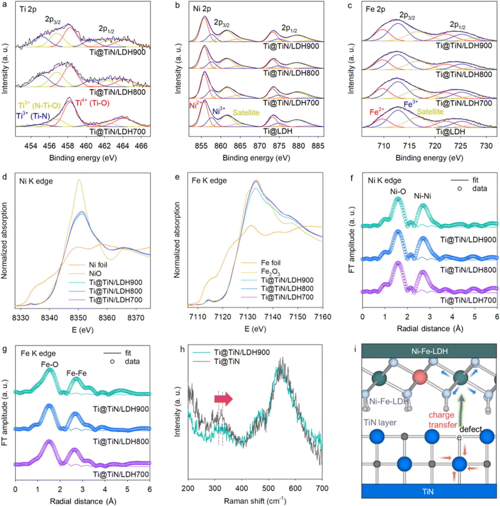
As presented in Fig. S1,† the precursor of the Ti@TiO2 foam displayed Bragg reflections of the anatase TiO2 phase and Ti metal, indicating the formation of a TiO2 layer on the Ti foam. The ammonolysis of the Ti@TiO2 foam at 700–900 °C induced the advent of TiN-related XRD peaks (Fig. S2†), indicating nitridation of the TiO2 layer. While Ti@TiN700 still showed the XRD peaks of anatase TiO2, TiN, and Ti, both Ti@TiN800 and Ti@TiN900 displayed TiN- and Ti-related Bragg reflections with the disappearance of TiO2-related peaks. This finding demonstrated that the elevation of the ammonolysis temperature to 800 °C was necessary to induce a complete phase transition from TiO2 to TiN. As shown in Fig. 1b, the deposition of Ni–Fe-LDH on the Ti@TiN substrate led to the appearance of Bragg reflections of Ni–Fe-LDH as well as TiN and Ti, indicating the successful deposition of Ni–Fe-LDH on the Ti@TiN substrate. As illustrated in Fig. 1c, the FE-SEM analysis for Ti@TiO2 clearly demonstrated the deposition of 2D TiO2 nanoplates on the Ti foam. The subsequent ammonolysis of the Ti@TiO2 foam resulted in the transformation into holey TiN nanoplates. The generation of surface holes in the TiN nanoplates originated from the aliovalent substitution of divalent O2− ions with trivalent N3− ions that caused the formation of anion vacancies.12,18 The creation of numerous nitrogen vacancies in very thin 2D nanoplates resulted in the formation of surface holes. During the phase transformation, the holey TiN nanoplates remained robustly anchored to the Ti foam. In addition, FE-SEM analysis of Ti@TiN/LDH confirmed the immobilization of LDH nanosheets on the Ti@TiN foam (Fig. 1c, S3, and S4†). As shown in Fig. 1d, TEM analysis offered compelling proof for the formation of intimately coupled TiN and LDH nanodomains showing distinct lattice fringes of both components. The uniform anchoring of Ni–Fe-LDH on the surface of the Ti@TiN foam was further corroborated by EDS analysis with elemental mapping, which revealed a uniform distribution of Ti, Ni, and Fe (Fig. 1e). The ratio of NiFeLDH/TiN in the Ti@TiN/LDH nanohybrid was determined by elemental analysis, as presented in Table S1.†The interfacial chemical interactions in Ti@TiN/LDH and Ti@TiN were investigated using surface-sensitive XPS. The significant influence of the ammonolysis temperature and hybridization on the bonding nature of the deposited TiN buffer layer was evidenced by the Ti 2p XPS data. As presented in Fig. S5a,† all Ti@TiN materials displayed diffusive features comprising Ti3+–N, N–Ti3+–O, and Ti4+–O components.18 The increase in the ammonolysis temperature induced a gradual increase in the spectral weight of the low-energy components, reflecting a reduction in the Ti oxidation state from Ti4+ to Ti3+. Peak deconvolution analysis demonstrated that the spectral weights of Ti3+–N and N–Ti3+–O increased with the ammonolysis temperature, confirming the promotion of nitridation at elevated temperatures. Even though the XRD results verified the complete phase transition into a TiN structure in Ti@TiN800/LDH and Ti@TiN900/LDH, the Ti 2p XPS data of these materials still showed the presence of significant amounts of Ti4+ species. Considering the high sensitivity of XPS to surface species, this observation could be understood as being a result of the atmospheric oxidation of surface Ti3+ species in the TiN phase, as reported previously.31 As plotted in Fig. S5b,† the N 1s XPS data for all Ti@TiN materials were composed of surface Ti–N–O, Ti–N, and Ti–N–O components.32,33 Peak deconvolution analysis revealed that the increase in the ammonolysis temperature led to the depression of the surface Ti–N–O component, suggesting the prevention of surface oxidation of the TiN layer. This was caused by the sintering effect at elevated temperatures. In the Ti 2p XPS data of Fig. 2a, similar to the Ti@TiN materials, all Ti@TiN/LDH materials showed enhanced Ti3+-related components in the lower energy region upon increasing the ammonolysis temperature. This result can also be interpreted as being a result of enhanced nitridation with increasing ammonolysis temperatures. All Ti@TiN/LDH nanohybrids had higher concentrations of Ti4+–O components than the corresponding Ti@TiN materials (Fig. S5a†), which emphasized the presence of interfacial Ti–O bonds between TiN and the LDH, and the increase of Ti valence state due to the interfacial electron transfer. As can be seen from the Ni 2p and Fe 2p regions (Fig. 2b and c), typical spectral features of Ni–Fe-LDH comprising Ni2+/Fe2+ and Ni3+/Fe3+ components were discernible for all Ti@TiN/LDH materials, substantiating the formation of the Ni–Fe-LDH phase (Table S2†). The overlapped spectra of deconvoluted peaks in Fig. S6† clearly demonstrated that, with respect to Ti@LDH, all Ti@TiN/LDH materials showed higher ratios of Ni2+/Ni3+ and Fe2+/Fe3+, corroborating the enhancement of charge transfer from holey TiN to Ni–Fe-LDH upon the intervention of the holey TiN buffer layer.
 | ||
| Fig. 2 (a) Ti 2p XPS, (b) Ni 2p XPS, (c) Fe 2p XPS, (d) Ni K-edge XANES, (e) Ni K-edge XANES, (f) Ni K-edge FT-EXAFS, and (g) Fe K-edge FT-EXAFS, and (h) micro-Raman data. (i) Schematic illustration for interfacial coordination between holey TiN and Ni–Fe-LDH. | ||
The oxidation state and local structure of Ni–Fe–LDH deposited on the Ti@TiN foam were characterized using bulk-sensitive XANES and EXAFS analysis. As illustrated in Fig. 2d and e, the Ni and Fe K-edge XANES data of the Ti@TiN/LDH materials exhibit similar edge energies to those of the reference materials, namely NiO and Fe2O3, indicating the presence of Ni2+ and Fe3+ oxidation states in these materials. In Fig. 2f and g, all Ti@TiN/LDH nanohybrids displayed characteristic Ni K- and Fe K-edge EXAFS data, including two intense Fourier transform peaks at 1.6 and 2.6 Å that were assigned to Ni/Fe–O and edge-shared Ni/Fe–Ni/Fe coordination shells, respectively, which are typical of brucite LDH layers.12,13 As presented in Table S3,† the least squares fitting analysis revealed that the bond distances of Ni/Fe–O bonding pairs in the Ti@TiN/LDH materials became longer upon the increase in ammonolysis temperature, attesting to the promotion of electron transfer between TiN and LDH. Because of the difficulty in acquiring distinct XANES signals of the TiN species in Ti@TiN/LDH materials due to the coverage by LDH crystallites, micro-Raman analysis was conducted to characterize the chemical bonding nature of the TiN species in the hybrid materials. As shown in Fig. 2h, Ti@TiN and Ti@TiN/LDH900 exhibit typical Raman data of the TiN phase, i.e., the acoustic vibrational mode of TiN at ∼320 cm−1 and the optical vibrational mode of TiN and/or overtone of the acoustic mode at ∼450–600 cm−1, respectively.34 This observation provided another confirmation for the retention of the TiN structure following the hybridization.13 Hybridization with the LDH led to a distinct high-energy displacement of the phonon lines at approximately 320 cm−1. This shift indicated the creation of nitrogen vacancies caused by interfacial interactions with the LDH species because the energy of this Raman peak showed a good correlation with the content of nitrogen vacancies.35 The creation of nitrogen vacancies upon the hybridization between TiN and Ni–Fe-LDH accorded well with the density functional theory (DFT) calculation predicting the lowering of defect formation energy upon hybridization.12 In contrast, the main peaks of Ti@TiN/LDH in the region of ∼400–600 cm−1 experienced a lower-energy shift upon the hybridization with LDH. Considering that the Ni–Fe-LDH material showed a distinct peak at around ∼530 cm−1,12 the observed peak shift could be interpreted as being evidence for the combination of the Raman spectral features of TiN and LDH. As illustrated in Fig. 2i, combined spectroscopic investigation clearly demonstrated the occurrence of electron transfer from holey TiN to Ni–Fe-LDH via enhanced interfacial interactions by the intervention of the holey TiN buffer layer, which was well-consistent with the previously reported DFT calculation.12
To examine the impact of the TiN buffer layer on the electrocatalyst functionality of the deposited Ni–Fe-LDH material, the electrocatalyst performances of Ti@TiN/LDH materials were tested for the OER process in an aqueous 1 M KOH solution using the SCE reference electrode. As depicted in Fig. 3a and b, the LSV results revealed that Ti@TiN/LDH700, Ti@TiN/LDH800, and Ti@TiN/LDH900 delivered excellent OER activities with small overpotentials of 250, 245, and 240 mV at 100 mA cm−2, respectively, which are much lower than that of the commercial RuO2 reference (324 mV) (see Fig. S7†). As summarized in Table S4,† the obtained OER electrocatalytic activity of Ti@TiN/LDH900 is one of the best performances among the recently reported data. The influence of the type of reference electrode was probed by the measurement of LSV data using the Hg/HgO electrode. As plotted in Fig. S8,† the OER activity data obtained with the Hg/HgO electrode were found to be nearly identical to those obtained with the SCE electrode, which allowed the influence of reference electrode type to be ruled out. The LSV polarization curves without iR compensation are shown in Fig. S9.† Ti@TiN/LDH900 exhibited the highest OER activity among the investigated Ti@TiN/LDH nanohybrids, which was ascribed to the enhanced electrical conductivity of the TiN layer and the reinforced interfacial coupling via the nitridation at 900 °C. A further elevation of the ammonolysis temperature to 1000 °C led to the degradation of the OER activity of the Ti@TiN/LDH material (Fig. S10†). This result confirmed that ammonolysis at 900 °C was the optimal condition for improving the OER activity of the anchored LDH materials.
 | ||
| Fig. 3 (a) LSV of the OER with iR correction, (b) overpotentials, (c) Tafel slopes, (d) ECSA, (e) durability, and (f) EIS data of Ti@TiN/LDH700–900 measured in 1 M KOH electrolyte. | ||
To examine the impact of chemical compositions, additional Ti@TiN/LDH900 materials with different TiN/LDH ratios were prepared and tested as OER electrocatalysts. The change of chemical composition degraded the OER activity, confirming the optimal ratio of TiN/Ni–Fe-LDH in this material, as presented in Fig. S11.† As shown in Fig. 3b, all Ti@TiN/LDH hybrid materials exhibited superior OER performances compared with that of the Ti@LDH reference. This result highlighted the high efficacy of the TiN buffer introduction in optimizing the electrocatalytic performance of the immobilized Ni–Fe-LDH. The enhanced OER functionality of the Ti@TiN/LDH nanohybrids was further corroborated by Tafel slope calculations. As illustrated in Fig. 3c, all Ti@TiN/LDH nanohybrids showed smaller Tafel slopes of 73.5–100.9 mV dec−1 than those of Ti@LDH (126.6 mV dec−1) and Ti@TiN (208.9 mV dec−1), emphasizing an improvement in the electrolysis kinetics caused by the introduction of a holey TiN layer between the Ti foam and LDH materials.12 Based on the electrochemical double-layer capacitance (Fig. 3d and S12†), the ECSAs of the Ti@TiN/LDH materials were estimated to be 153.5–173.3 mF cm−2, which were notably greater than those of Ti@LDH (0.2 mF cm−2) and Ti@TiN (124.4 mF cm−2). The larger ECSAs of Ti@TiN/LDH compared with those of Ti@LDH were attributed to the enhanced electrical connection between the LDH and Ti foam by the intervention of the holey TiN layer and/or to the improvement in mass transport provided by the holey 2D morphology of the TiN layer. As presented in Fig. 3e, the Ti@TiN/LDH900 nanohybrid exhibited a stable OER activity over 100 h at a current density of 100 mA cm−2, underscoring the benefit of TiN intervention in enhancing the electrocatalytic stability. As depicted in Fig. S13,† the durability of Ti@TiN/LDH900 was better than those of Ti@TiN/LDH800 and Ti@TiN/LDH700, attesting to its superior electrocatalyst functionality. The outstanding stability of the Ti@TiN/LDH900 nanohybrid was further corroborated by XRD, and FE-SEM analyses exhibiting the retention of the original structure, morphology, and composition after the stability test for 100 h (see Fig. S14†). EIS analysis (Fig. 3f) clearly demonstrated that the introduction of the TiN buffer layer significantly reduced the radius of the semicircle at 1.49 V vs. the RHE in the Nyquist plot, emphasizing the improved charge transport properties of Ti@TiN/LDH.36,37 Among the investigated materials, the charge transfer resistance (Rct) of the Ti@TiN/LDH900 nanohybrid was lower than that of the other Ti@TiN/LDH homologs (Table S5†), corroborating the reinforcement of electrical connection between LDH and Ti foam with increasing ammonolysis temperature. The lower charge-transfer resistance of Ti@TiN/LDH900 than Ti@LDH underlined the benefit of introducing a holey TiN buffer layer in optimizing the charge transport properties of the anchored Ni–Fe-LDH.
The validity of Ti@TiN/LDH nanohybrids as seawater OER electrocatalysts was examined by measuring the LSV data in a simulated seawater electrolyte containing 0.5 M NaCl and 1 M KOH. To selectively measure the OER activity, an electrocatalytic activity test was conducted below 1.72 V versus the RHE, in which no chloride oxidation occurred.38 As presented in Fig. 4a and b, an excellent OER performance occurred for Ti@TiN/LDH900 with a small overpotential of 250 mV at 100 mA cm−2, which was comparable to the overpotential measured in aqueous 1 M KOH medium (240 mV). Similar to the results obtained with an aqueous 1 M KOH electrolyte, Ti@TiN/LDH900 displayed a higher OER activity than the other homologs, namely Ti@TiN/LDH700, Ti@TiN/LDH800, and Ti@LDH. Notably, the OER activity of Ti@LDH was significantly poorer in simulated seawater than in NaCl-free media. This is in sharp contrast to Ti@TiN/LDH, which showed good retention of its OER performance. This result emphasized the pivotal function of the holey TiN buffer layer in increasing the catalytic functionality for seawater electrolysis. Amongst the investigated materials, Ti@TiN/LDH900 showed the smallest Tafel slope of 74.8 mV dec−1 in the simulated seawater electrolyte (Fig. 4c). The Tafel slopes of this material in simulated seawater were comparable to those in aqueous 1 M KOH electrolyte. As plotted in Fig. 4d, although the OER performance of Ti@TiN/LDH900 became slightly further depressed in real seawater electrolyte, this material still showed promising OER performance. Like the data in simulated seawater electrolyte, both Ti@TiN/LDH700 and Ti@TiN/LDH800 materials delivered lower OER activity in real seawater electrolyte with respect to that of Ti@TiN/LDH900, highlighting that the nitridation at 900 °C is an optimal condition to improve the OER catalyst functionality of Ti@TiN/LDH (Fig. S15†). This result corroborated the validity of the introduction of a holey TiN layer for promoting seawater electrolysis. The introduction of a holey TiN layer with abundant nitrogen vacancies was supposed to facilitate the selective adsorption of OH− ions over Cl− ions because of the similar chemical natures of nitrogen and oxygen ions. This prevented the interference effect of chloride adsorption on catalytically active sites. The excellent OER activity and durability of Ti@TiN/LDH900 were also demonstrated by a stability test in alkaline seawater electrolyte. As shown in Fig. 4e, this material retained excellent durability up to 100 h both in simulated seawater and real seawater electrolytes, stressing the high efficacy of the holey TiN buffer layer in developing efficient seawater electrocatalysts.
 | ||
| Fig. 4 (a) LSV of the OER with iR correction, (b) overpotentials, and (c) Tafel slopes measured in simulated seawater (i.e., 1 M KOH + 0.5 M NaCl) electrolyte. (d) Comparison of LSV data with iR correction and (e) durability data of Ti@TiN/LDH900 measured in simulated seawater and real seawater electrolytes. | ||
To elucidate the underlying mechanism of the impact of the holey TiN buffer layer on the electrocatalytic activity of the immobilized LDH species, the structural changes in Ti@TiN/LDH during the electrocatalytic OER were examined using in situ Raman spectroscopy. To improve the signal-to-noise ratio of the Raman signal, a specially designed in situ cell with simulated seawater medium was used for the in situ Raman measurements, as depicted in Fig. 5a. Before the application of the electrical potential, the spectral features typical of Ni–Fe-LDH, including two intense phonon lines at approximately 530 and 690 cm−1, were discernible for Ti@LDH, while the Ti@TiN/LDH900 showed the dominant Raman peaks of the TiN phase,12,13 as shown in Fig. 5b. The loading of the oxidative potential (1.45 V) for Ti@TiN/LDH900 resulted in the appearance of new Raman features corresponding to γ-NiOOH at approximately 480 and 560 cm−1, emphasizing the formation of an oxidized trivalent metal oxyhydroxide phase.13 Conversely, the appearance of γ-NiOOH-related phonon lines was not distinct for Ti@LDH at the same potential (1.45 V), confirming the lower redox activity of Ti@LDH than Ti@TiN/LDH. It is necessary to increase the oxidation bias to 1.55 V to induce the appearance of γ-NiOOH-related peaks for Ti@LDH. This finding proved the promotion of the structural transformation of Ni–Fe-LDH into γ-NiOOH upon the intervention of the holey TiN buffer layer, as depicted in Fig. 5c. Since this reversible phase transformation has been well known to play a crucial role in the OER activity of Ni–Fe-LDH,39 the observed enhanced structural transformation highlighted the pivotal function of the intervening holey TiN buffer layer in facilitating the redox process of the deposited Ni–Fe-LDH electrocatalysts, hence enhancing the OER activity via effective reinforcement of the electronic connection between Ni–Fe-LDH and the Ti substrate.40 In addition, the Ti@LDH material displayed the advent of a distinct peak at 700 nm at 1.55 V, which could be attributed to the adsorbed carbonate ions.41 The formation of carbonate ions caused by the dissolution of CO2 molecules was promoted in the alkaline electrolyte, which is responsible for the appearance of this carbonate-related Raman peak in the Ti@LDH. In contrast, this carbonate-related peak was not discernible for the Ti@TiN/LDH900 nanohybrid. The absence of this peak could be ascribed to the high OER activity of Ti@TiN/LDH900, because the promoted OER process led to the rapid consumption of hydroxide ions and the prevention of CO2 dissolution via the lowering of solution pH in the vicinity of the electrocatalyst. The in situ Raman results demonstrated that Ti@holey-TiN with abundant nitrogen vacancies could be used as a versatile hybridization substrate for electrocatalyst materials via interfacial bonding with anchored Ni–Fe-LDH crystallites.
 | ||
| Fig. 5 (a) Instrumental setting for in situ Raman analysis. (b) In situ Raman data during the OER for Ti@TiN/LDH900 and Ti@LDH. (c) Impact of the TiN buffer layer on the phase transition behavior of anchored Ni–Fe-LDH species. (d) Scheme for efficient electronic coupling between the LDH and TiN buffer layer. | ||
In summary, several factors contributed to the benefit of the holey TiN buffer layer in achieving a highly selective OER performance of the immobilized LDH phase in a seawater electrolyte, as illustrated in Fig. 5d. First, the interfacial interaction between holey TiN and Ni–Fe-LDH led to an improvement in the charge transfer properties through the enhanced electronic connection between the Ni–Fe-LDH electrocatalysts and Ti foam. Such efficient electronic interaction of the LDH with the conductive Ti@TiN matrix also enabled the increase of ECSA, which additionally contributed to the enhanced electrocatalyst functionality of the hybridized LDH. In addition, the enhancement in charge transfer properties resulted in the elevation of the d-band center of Ni–Fe-LDH, leading to an improvement in the bond strength with OH− ions during the OER process, thereby enhancing the electrocatalytic activity of Ni–Fe-LDH, as reported previously.12,42,43 Second, the introduction of nitrogen vacancies in the TiN buffer layer helped promote the adsorption of OH− ions, whereas the Ni and Fe ions in the vicinity of N vacancies acted as catalytically active sites to oxidize the adsorbed OH− ions to produce O2 molecules. In addition, the increase in nitrogen vacancies assisted in the selective adsorption of OH− ions over Cl− ions owing to the similar size and chemical nature of nitrogen and oxygen.36,37 This was responsible for the maintenance of an excellent OER activity in seawater. Although the hybridization with LDH might induce the partial blocking of the nitrogen vacancies, the additional formation of nitrogen vacancies caused by the interfacial electronic coupling with LDH also contributed to the improvement of electrocatalytic performance upon hybridization.12 Third, the prevention of the agglomeration of LDH nanoplates on the strongly coupled Ti@TiN substrate facilitated the electrolyte transport in electrocatalytic reactions.44 In addition, the porous morphology of the LDH provided a large number of catalytic sites and promoted the access of OH− ions to the surface reaction sites of the LDH.45–47
Conclusions
In this study, an interface-control approach was developed to explore highly efficient electrocatalysts for seawater electrolysis. This approach involved the incorporation of a holey TiN layer between the Ti foam and electrocatalyst layer. The introduction of a holey TiN buffer layer was highly effective in increasing the electrocatalytic activity of Ni–Fe-LDH materials immobilized on a Ti foam for alkaline seawater electrolysis. In situ Raman investigation underscored that the unsaturated coordination of holey defective TiN layers played a crucial role in forming interfacial coordination bonds and reinforcing the electronic interaction with the immobilized LDH layer, leading to a promotion of the redox process of the LDH. In addition, the reinforced electrical connection between the LDH layer and Ti foam upon introduction of the holey TiN buffer layer resulted in the optimization of charge/mass transfer and enhancement of the OER kinetics and ECSA. These factors assisted in the introduction of a TiN layer that improved the electrocatalyst functionality of the immobilized LDH materials. Furthermore, the presence of abundant nitrogen vacancies in the buffer TiN layer enhanced the selective attachment of OH− ions over Cl− ions in seawater, which prevented the interference of adsorbed Cl− ions on active sites. The preferred adsorption of hydroxide ions on the TiN-containing hybrid structure was responsible for the retention of a good OER performance in the real seawater electrolyte. Considering the efficient role of conductive holey TiN as a buffer layer in enhancing the electrical conductivity of electrocatalyst materials deposited on porous Ti foam, the present interface engineering strategy could provide an efficient means to explore efficient electrode materials for secondary batteries and supercapacitors.Data availability
The data supporting this article have been included as part of the ESI.†Author contributions
Conceptualization: SJH; methodology: WY, XJ, SJH; investigation: WY, YHP; formal analysis: WY, YHP, XJ; visualization: WY, XJ; funding acquisition: SJH; supervision: XJ, SJH; writing—original draft: SJH; writing—review & editing: XJ, SJH.Conflicts of interest
There are no conflicts to declare.Acknowledgements
This work was financially supported by the National Research Foundation of Korea (NRF) grant funded by the Korean government (MSIT) (RS-2023–00208355, RS-2024-00439825, 2022M3H4A4086103, and 2021M3H4A1A03049662). The experiments at PAL were supported in part by MOST and POSTECH.References
- D. Du, H. He, R. Zheng, L. Zeng, X. Wang, C. Shu and C. Zhang, Adv. Energy Mater., 2024, 14, 2304238 CrossRef CAS.
- N. H. Kwon, X. Jin, S.-J. Kim, H. Kim and S.-J. Hwang, Adv. Sci., 2022, 9, 2103042 CrossRef CAS.
- U. N. Pan, M. R. Kandel, A. K. Tomar, N. H. Kim and J. H. Lee, Small, 2024, 20, 2305519 CrossRef CAS.
- N. H. Kwon, S. Y. Yun, J. Lim and S.-J. Hwang, Nano Energy, 2024, 122, 109315 CrossRef CAS.
- R. Zheng, D. Du, Y. Yan, S. Liu, X. Wang and C. Shu, Adv. Funct. Mater., 2024, 34, 2316440 CrossRef CAS.
- V. H. Hoa, M. Austeria, H. T. Dao, M. Mai and D. H. Kim, Appl. Catal., B, 2023, 327, 122467 CrossRef CAS.
- J.-T. Ren, L. Chen, L. Wang, X.-L. Song, Q.-H. Kong and Z.-Y. Yuan, J. Mater. Chem. A, 2023, 11, 2899 RSC.
- Y. Sun, J. Lee, N. H. Kwon, J. Lim, X. Jin, Y. Gogotsi and S.-J. Hwang, ACS Nano, 2024, 18, 6243 CrossRef CAS PubMed.
- J. Lee, J. Lee, X. Jin, H. Kim and S.-J. Hwang, Small, 2024, 20, 2306781 CrossRef CAS.
- C. Yue, X. Zhang, J. Yin, H. Zhou, K. Liu and X. Liu, Appl. Catal., B, 2023, 339, 123171 CrossRef CAS.
- M. Wei, M. Li, Q. Gao, X. Cai, S. Zhang, Y. Fang, F. Peng and S. Yang, Small, 2024, 20, 2305906 CrossRef CAS.
- X. Jin, T. Lee, W. Tamakloe, S. B. Patil, A. Soon, Y.-M. Kang and S.-J. Hwang, Adv. Sci., 2022, 9, 2103368 CrossRef CAS PubMed.
- Y. H. Park, S. B. Patil, X. Jin and S.-J. Hwang, Nano Energy, 2023, 113, 108566 CrossRef CAS.
- J. Chen, X. Wei, J. Zhang, Y. Luo, Y. Chen, G. Wang and R. Wang, Ind. Eng. Chem. Res., 2019, 58, 2741–2748 CrossRef CAS.
- U. Mahajan, M. Dhonde, K. Sahu, P. Ghosh and P. M. Shirage, Mater. Adv., 2024, 5, 846 RSC.
- J. Zhao, Y. Zeng, J. Wang, Q. Xu, R. Chen, H. Ni and G. J. Cheng, Nanoscale, 2020, 12, 15393–15401 RSC.
- W. Wen, Y.-N. Chen, S.-G. Wang, M.-H. Cao, J.-C. Yao, Y.-J. Gu and J.-M. Wu, Appl. Mater. Today, 2018, 12, 276 CrossRef.
- X. Jin, K.-G. Lee, T. Lee, G. Lee, S. M. Oh, A. Soon and S.-J. Hwang, Chem. Eng. J., 2022, 437, 135415 CrossRef CAS.
- N. Kim, T.-H. Gu, D. Shin, X. Jin, H. Shin, M. G. Kim, H. Kim and S.-J. Hwang, ACS Nano, 2021, 15, 8306 CrossRef CAS.
- F. Wang, P. Zou, Y. Zhang, W. Pan, Y. Li, L. Liang, C. Chen, H. Liu and S. Zheng, Nat. Commun., 2023, 14, 6019 CrossRef CAS PubMed.
- G. Tian, H. Xu, X. Wang, X. Wen, T. Zeng, S. Liu, F. Fan, W. Xiang and C. Shu, Nano Energy, 2023, 117, 108863 CrossRef CAS.
- G. Tian, L. Ren, H. Xu, T. Zeng, X. Wang, X. Wen, D. Du, Y. Yan, S. Liu and C. Shu, Sci. China Mater., 2023, 66, 1341 CrossRef CAS.
- R. Kulkarni, L. P. Lingamdinne, R. R. Karri, Z. H. Momin, J. R. Koduru and Y.-Y. Chang, Coord. Chem. Rev., 2023, 497, 215460 CrossRef CAS.
- Y. Liao, R. He, W. Pan, Y. Li, Y. Wang, J. Li and Y. Li, Chem. Eng. J., 2023, 464, 142669 CrossRef CAS.
- H. Jiang, Y. Yu, X. Duan, P. Chen, S. Wang, X. Qiu, L. Ye and X. Tu, Small, 2024, 20, 2307797 CrossRef CAS.
- S. Pal, K. Shimizu, S. Khatun, S. Singha, S. Watanabe and P. Roy, J. Mater. Chem. A, 2023, 11, 12151 RSC.
- X. Ruan, S. Li, C. Huang, W. Zheng, X. Cui and S. K. Ravi, Adv. Mater., 2023, 36, 2305285 CrossRef.
- M. S. Javed, A. Mateen, I. Hussain, A. Ahmad, M. Mubashir, S. Khan, M. A. Assiri, S. M. Eldin, S. S. A. Shah and W. Han, Energy Storage Mater., 2022, 53, 827–872 CrossRef.
- T. Xu, Y. Xue, J. Li and Y. Wang, Chem. Eng. J., 2023, 470, 144247 CrossRef CAS.
- S.-J. Hwang, C.-W. Kwon, J. Portier, G. Campet, H.-S. Park, J.-H. Choy, P. V. Huong, M. Yoshimura and M. Kakihana, J. Phys. Chem. B, 2002, 106, 4053–4060 CrossRef CAS.
- W.-C. Peng, Y.-C. Chen, J.-L. He, S.-L. Ou, R.-H. Horng and D.-S. Wuu, Sci. Rep., 2018, 8, 9255 CrossRef PubMed.
- I. Milošev, H.-H. Strehblow, B. Navinšek and M. Metikoš-Huković, Surf. Interface Anal., 1995, 23, 529–539 CrossRef.
- B. Guo, J. Sun, X. Hu, Y. Wang, Y. Sun, R. Hu, L. Yu, H. Zhao and J. Zhu, ACS Appl. Nano Mater., 2019, 2, 40–47 CrossRef CAS.
- W. Spengler, R. Kaiser, A. N. Christensen and C. Müller-Vogt, Phys. Rev. B: Condens. Matter Mater. Phys., 1978, 17, 1095 CrossRef CAS.
- Y. H. Cheng, B. K. Tay, S. P. Lau, H. Kupfer and F. Richter, J. Appl. Phys., 2002, 92, 1845–1849 CrossRef CAS.
- H. W. Choi, J. Kim, H.-S. Bang, K. Badawy, U. Y. Lee, D. I. Jeong, Y. Lim, K. Hamad, B. K. Kang, B. M. Weon, H.-S. Oh, N. Singh and D. H. Yoon, J. Mater. Chem. A, 2024, 12, 7067 RSC.
- S. Anantharaj and S. Noda, ChemElectroChem, 2020, 7, 2297 CrossRef CAS.
- S. Khayun, H. Hirani and P. Roy, J. Mater. Chem. A, 2021, 9, 74 RSC.
- Z. He, J. Zhang, Z. Gong, H. Lei, D. Zhou, N. Zhang, W. Mai, S. Zhao and Y. Chen, Nat. Commun., 2022, 13, 2191 CrossRef CAS.
- X. Liu, Z. Chen and M. Cao, ACS Appl. Energy Mater., 2019, 2, 5960–5967 CrossRef CAS.
- R. L. Frost, A. López, R. Scholz, Y. Xi and F. M. Belotti, J. Mol. Struct., 2013, 1051, 221 CrossRef CAS.
- L. Yin, X. Du, C. Di, M. Wang, K. Su and Z. Li, Chem. Eng. J., 2021, 414, 128809 CrossRef CAS.
- Y.-H. Wang, L. Li, J. Shi, M.-Y. Xie, J. Nie, G.-F. Huang, B. Li, W. Hu, A. Pan and W.-Q. Huang, Adv. Sci., 2023, 10, 2303321 CrossRef CAS PubMed.
- L. Yu, J. Xiao, C. Huang, J. Zhou, M. Qiu, Y. Yu, Z. Ren, C.-W. Chu and J. C. Yu, Proc. Natl. Acad. Sci. U. S. A., 2022, 119, e2202382119 CrossRef CAS PubMed.
- J. Zhao, N. Liao and J. Luo, J. Mater. Chem. A, 2023, 11, 9682 RSC.
- P. Long, M. Qin, B. Zhang, Q. Liu, F. Zhao, Z. Wu, Z. Ni, H. Yu, F. Li, H. Song, Y. Feng and W. Feng, Carbon, 2023, 212, 118088 CrossRef CAS.
- H. Zhang, L. Wu, R. Feng, S. Wang, C.-S. Hsu, Y. Ni, A. Ahmad, C. Zhang, H. Wu, H.-M. Chen, W. Zhang, Y. Li, P. Liu and F. Song, ACS Catal., 2023, 13, 6000 CrossRef CAS.
Footnotes |
| † Electronic supplementary information (ESI) available. See DOI: https://doi.org/10.1039/d4ta02886d |
| ‡ These authors contributed equally to this work. |
| This journal is © The Royal Society of Chemistry 2024 |