Detailed investigation of a NaTi2(PO4)3 anode prepared by pyro-synthesis for Na-ion batteries†
Yubin Niuab,
Maowen Xu*ab,
Yan Zhangab,
Jin Hanab,
Yan Wangab and
Chang Ming Li*abc
aInstitute for Clean Energy & Advanced Materials, Faculty of Materials and Energy, Southwest University, Chongqing 400715, P. R. China. E-mail: xumaowen@swu.edu; cn.ecmli@swu.edu.cn
bChongqing Key Laboratory for Advanced Materials and Technologies of Clean Energies, Chongqing 400715, P. R. China
cInstitute of Materials Science and Devices, Suzhou University of Science and Technology, Suzhou 215011, P. R. China
First published on 5th May 2016
Abstract
NaTi2(PO4)3 nanoparticles were synthesized by a facile polyol-assisted pyro-synthetic reaction. The nitrogen sorption isotherm of the synthesized material shows a surface area of 110.787 m2 g−1, in comparison to 20.984 m2 g−1 for pristine material obtained by a solid state method. Moreover, the as-prepared material exhibits much higher capacity, better rate performance and lower electrochemical polarization, of which the excellent electrochemical performance is mainly attributed to uniform particle distribution, good structural stability, high specific surface area, significantly enhanced diffusion coefficient and good conductivity. Through systematic studies using a galvanostatic intermittent titration technique (GITT) and electrochemical impedance spectroscopy (EIS) at different states of charge and discharge, the Na+ diffusion coefficient shows a minimum value at the end of the two-phase region.
Introduction
Sodium ion batteries (SIBs) with large energy density, long life span, high efficiency, high safety and low cost have been greatly considered as an alternative to lithium-ion ones. Recently, the electrochemical insertion reaction mechanism of sodium has stimulated much interest in numerous transition metal phosphates, fluorophosphates and pyrophosphates such as Na3V2(PO4)3,1 Na2Fe3(PO4)3,2 NaFePO4,3 Na2FePO4F,4 Na3V2O2(PO4)2F5,6 and Na7Fe7(PO4)6F3,7 Na3.12Fe2.44(P2O7)2.8–10 Although the research focuses on the cathode materials, the knowledge of rational polyanionic frameworks of the electrode materials for stable structural stability and large ion diffusion channels11 has significance on the development of the anode materials. As a typical superior ion-conducting structure for sodium ions, NaTi2(PO4)3 (NTP) is one of the promising anodes in non-aqueous12–15 and aqueous16–18 SIBs. For the former, it displays a well-defined redox plateau (∼2.1 V vs. Na/Na+), high theoretical specific capacity (132.8 mA h g−1), structural stability and intrinsic safety.13,15,19–21 Most importantly, it is also a zero-strain insertion material based on a relatively high Na insertion–deinsertion voltage plateau, which can avoid formation of the solid electrolyte interphase (SEI), thereby increasing coulombic efficiency and safety performance.Although the open 3D framework of a NASICON-type structure is suitable for Na+ diffusion, its poor electronic conductivity has slow transport of Na+.14 Obviously, electronic and ionic conductivity play a crucial role in performance of electrode materials. To overcome these shortcomings, coating highly conductive carbonaceous materials and well-tailored particle size are needed to enhance conductivity.13–15,17,20,21 Besides, for the practical application, it is important to large-scale synthesize the electrode materials without using expensive experimental instruments and rigorous procedures.13,17,20 To the best of our knowledge, no report is available on NTP obtained by simple and time-efficient pyro-synthetic method and their electrochemical performance as anode material for SIBs.
Herein, we employed a polyol mediated pyro-synthetic method, in which the polyol acts as both solvent and conductive carbon source, to fabricate amorphous carbon-coated NTP nanoparticles, denoted as p-NTP NPs, and then the change of diffusion coefficient of Na+ was studied systematically. In comparison to pristine material, denoted as NTP powders, obtained by solid state method, the resulted carbon-coated p-NTP NPs exhibit significantly improved anode performances at high charge–discharge rates in a Na-ion cell.
Experimental
Materials preparation
p-NTP NPs were obtained by the pyro-synthetic approach. Initially, sodium acetate (0.005 mol) and phosphoric acid (H3PO4, 0.015 mol) were dissolved in 100 mL of ethylene glycol in the molar ratio 1![[thin space (1/6-em)]](https://www.rsc.org/images/entities/char_2009.gif) :
:![[thin space (1/6-em)]](https://www.rsc.org/images/entities/char_2009.gif) 3 at room temperature with constantly stirring. Then, stoichiometry of tetrabutyl titanate (0.01 mol) was slowly added dropwise to the above solution. After obtaining a homogenous milky solution, the final solution was uniformly poured onto a hot-plate maintained at 200 °C. The polyol precursor solution was ignited with a torch to induce a self-extinguishable combustion process. Subsequently, the as-prepared intermediate was annealed at 600 °C for 5 hours under argon atmosphere to obtain the final product, namely, p-NTP NPs. For comparision, NTP powders were prepared by a traditional solid state process following the same experimental conditions except without adding ethylene glycol and the self-extinguishable combustion process.
3 at room temperature with constantly stirring. Then, stoichiometry of tetrabutyl titanate (0.01 mol) was slowly added dropwise to the above solution. After obtaining a homogenous milky solution, the final solution was uniformly poured onto a hot-plate maintained at 200 °C. The polyol precursor solution was ignited with a torch to induce a self-extinguishable combustion process. Subsequently, the as-prepared intermediate was annealed at 600 °C for 5 hours under argon atmosphere to obtain the final product, namely, p-NTP NPs. For comparision, NTP powders were prepared by a traditional solid state process following the same experimental conditions except without adding ethylene glycol and the self-extinguishable combustion process.
Morphology and structure characterization
The crystalline structures of the as-prepared products were investigated by using powder X-ray diffraction (XRD) with Cu Kα radiation (λ = 1.5416 Å) at a scanning rates of 2° min−1 over a range of 2θ = 10–80°. The morphologies and structures of both samples were observed by using a field-emission scanning electron microscope (FESEM) and energy dispersive spectroscopy (EDS; JEOL-6300F), transmission electron microscope (TEM) and high-resolution TEM (HRTEM; JEOL-2100 system). The thermal decomposition of the intermediate and the as-prepared product were investigated using a thermogravimetric analyser (TGA, TA Instruments, USA) at a heating rate of 5 °C min−1 under nitrogen and air flow from room temperature to 800 °C, respectively. The measurement of the specific surface area and analysis of the pore size distribution of the as-prepared materials were performed by measuring N2 adsorption/desorption isotherms with an Quadrasorb evo 2QDS-MP-30 surface area analyzer (Quantachrome Instruments, USA).To study the microstructure change and stability upon cycling, the electrodes (p-NTP NPs and NTP powders) were disassembled in a glovebox after being cycled. Then the electrodes were washed with dimethyl carbonate (DMC) to remove the electrolyte from the electrode surface and dried in vacuum at room temperature overnight. The crystalline structures and surface morphologies of the electrodes were examined by SEM, TEM and XRD.
Electrochemical measurements
Electrochemical testing of the as-prepared materials was performed by using coin cells with sodium metal as the counter electrode. The working electrode was prepared by the as-prepared materials, acetylene black, and PVdF at a weight ratio of 70![[thin space (1/6-em)]](https://www.rsc.org/images/entities/char_2009.gif) :
:![[thin space (1/6-em)]](https://www.rsc.org/images/entities/char_2009.gif) 20
20![[thin space (1/6-em)]](https://www.rsc.org/images/entities/char_2009.gif) :
:![[thin space (1/6-em)]](https://www.rsc.org/images/entities/char_2009.gif) 10 with N-methyl-2-pyrrolidone (NMP) as a solvent upon the copper-foil substrate and then coating the resultant slurry on a Cu foil. CR2032-type coin cells were fabricated by sandwiching a porous Celgard 2400 separator between the working electrode and Na-metal foil in a high-purity Ar-filled glove box with both the moisture and oxygen content below 1 ppm. The electrolyte used was 1 M NaClO4 in a mixed solvent of ethylene carbonate (EC) and diethyl carbonate (DEC; 1
10 with N-methyl-2-pyrrolidone (NMP) as a solvent upon the copper-foil substrate and then coating the resultant slurry on a Cu foil. CR2032-type coin cells were fabricated by sandwiching a porous Celgard 2400 separator between the working electrode and Na-metal foil in a high-purity Ar-filled glove box with both the moisture and oxygen content below 1 ppm. The electrolyte used was 1 M NaClO4 in a mixed solvent of ethylene carbonate (EC) and diethyl carbonate (DEC; 1![[thin space (1/6-em)]](https://www.rsc.org/images/entities/char_2009.gif) :
:![[thin space (1/6-em)]](https://www.rsc.org/images/entities/char_2009.gif) 1 v/v) with 3 wt% fluoroethylene carbonate (FEC) as an additive. Galvanostatic discharge and charge cycling of the cells were conducted by using a LAND cycler (Wuhan Kingnuo Electronic Co., China) at several different rates, as indicated between cutoff potentials of 1.2 and 2.8 V (vs. Na/Na+). Cyclic voltammogram (CV) measurements were carried out at various scan rates (0.1, 0.2, 0.4 and 0.8 mV s−1) using an Arbin Instruments testing system. Electrochemical impedance spectroscopy (EIS) experiments were conducted in the frequency range of 0.01–100 kHz with a CHI600D electrochemical analyzer by applying an AC voltage of 5 mV amplitude. Before each EIS test, the cell was charged to a scheduled potential and then laid up for 3 h to ensure a stable state. The galvanostatic intermittent titration technique (GITT) measurement was programmed by supplying a constant current flux of 0.2C for 10 min followed by an open circuit stand for 80 min, respectively. Before EIS and GITT tests, the cells previously underwent three discharge–charge cycles, so that they can reach stabilization, delivering reversible capacity and owning a stable electrode/electrolyte interface.
1 v/v) with 3 wt% fluoroethylene carbonate (FEC) as an additive. Galvanostatic discharge and charge cycling of the cells were conducted by using a LAND cycler (Wuhan Kingnuo Electronic Co., China) at several different rates, as indicated between cutoff potentials of 1.2 and 2.8 V (vs. Na/Na+). Cyclic voltammogram (CV) measurements were carried out at various scan rates (0.1, 0.2, 0.4 and 0.8 mV s−1) using an Arbin Instruments testing system. Electrochemical impedance spectroscopy (EIS) experiments were conducted in the frequency range of 0.01–100 kHz with a CHI600D electrochemical analyzer by applying an AC voltage of 5 mV amplitude. Before each EIS test, the cell was charged to a scheduled potential and then laid up for 3 h to ensure a stable state. The galvanostatic intermittent titration technique (GITT) measurement was programmed by supplying a constant current flux of 0.2C for 10 min followed by an open circuit stand for 80 min, respectively. Before EIS and GITT tests, the cells previously underwent three discharge–charge cycles, so that they can reach stabilization, delivering reversible capacity and owning a stable electrode/electrolyte interface.
Results and discussion
Rational synthesis and structural properties of p-NTP NPs
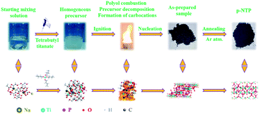
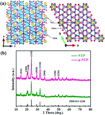
Scheme 1 illustrates our proposed method for the fabrication of the p-NTP NPs, in which all of the homogeneous starting precursors were dissolved in the polyol solution with continuous stirring until formation of a homogenous mixture, followed by pouring onto a hot-plate at 200 °C for a few minutes and then igniting with a torch to ultimately result in a polyol combustion for precursor decomposition and formation of carbocations along with the rapid nucleation and growing of NPs. It should be noted that the polyol acting as a low-cost fuel that induces a flame to release ultrahigh exothermic energy is essential for precursor decomposition and subsequent nucleation of nanoparticles. The entire reaction is a continuous process completing in a few minutes. In addition, the presence of H3PO4 accelerates the carbonization of the polyol to yield carbocations and carbon–carbon double bonds at high temperatures, and the resulted carbon network may act as electrical conduits between the particles may can improve the electrochemical properties at even high charge/discharge rates.22 Furthermore, by means of TGA, SEM and XRD techniques, the evolution of the intermediate to the final product has been traced, as shown in Fig. S1.† The results show that the NTP phase of the product has emerged after the pyro-synthesis, and after the post heat-treatment, the weight loss (13.16 wt%) is attributed to the further carbonization of the residual organic matter in the intermediate. As the annealing temperature increase, the peaks are getting more obvious and sharper and sharper, indicating the degree of crystallinity of the product is getting better. Taken together, these results suggest the post heat-treatment in argon atmosphere for a short sintering time is necessary.Fig. 1a schematically shows that the framework of NTP is built on an open 3D framework consisting of TiO6 octahedral and PO4 tetrahedron the structure.14,20 The newly synthesized materials were first examined with XRD as shown in Fig. 1b, which are consistent with the NTP pattern of JCPDS card number 33-1296, and no additional peaks from impurities are detected, indicating the high purity of the as-synthesised materials. Comparison to NTP powders, the intensity of the peaks of p-NTP NPs are much stronger, implying that the structure of the material is more orderly.
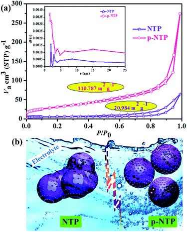
The microstructure and morphology of the as-prepared materials were investigated extensively by SEM and TEM. From Fig. 2 and S2,† we can see that the particles of p-NTP NPs have better dispersion and smaller size than those of NTP powders. The HRTEM image shows that the p-NTP NPs are wrapped with a thin layer of carbon (about 3.35 nm thick), which would offer a good electronic conductive network for the active materials. Both samples (p-NTP NPs and NTP powders) exhibit regular lattice fringes of the (116) crystalline plane with measured d (inter-planar) spacing of 0.273 nm and 0.279 nm, respectively. EDS element mapping analysis has been conducted to determine the element distribution of p-NTP NPs (Fig. S3†). As can be seen in Fig. S3b,† the peaks of C, O, Na, P and Ti can be obviously identified and no other peaks are observed, thus evidencing the elemental compositions. The measured and calculated values of the element contents are in good agreement (inset in Fig. S3b†), indicating the successful synthesise of phase-pure p-NTP. Moreover, as can be seen from Fig. S3c–f,† the O, Na, P and Ti atoms are homogeneously distributed throughout the whole selected p-NTP NPs (Fig. S3a†). The nitrogen isothermal adsorption–desorption measurement in Fig. 3a displays NTP powders and p-NTP NPs with specific surface areas of 20.984 and 110.787 m2 g−1, respectively. The pore size distributions of the as-prepared materials (inset in Fig. 3a) reveal that two of the samples have a similar average pore size of ∼2 nm, however, p-NTP NPs have bigger pore volume than that of NTP powders, indicating the former shows better porosity than that of the latter, which is beneficial for the penetration of the electrolyte, as shown in Fig. 3b. Accordingly, it can be concluded that the nanostructure of the p-NTP NPs obtained by pyro-synthesis offers a huge active surface area and structure stability for a large amount of active electrochemical reaction sites and reaction stability leading to a high specific capacity and cycling stability for the electrode of SIBs. Namely, Na ions can easily diffuse into and out of the p-NTP NPs due to their porous structures at the nanoscale that can are expected to significantly enhance the battery performance. The carbon content in p-NTP is estimated from TG analysis to be approximately 8.7 wt% (Fig. S4†).
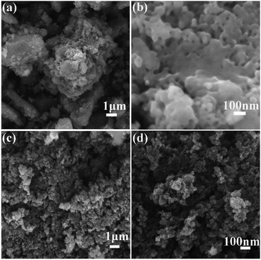 | ||
| Fig. 2 SEM images of NTP powders (a and b) and p-NTP NPs (c and d) under different magnification, respectively. | ||
Electrochemical performance
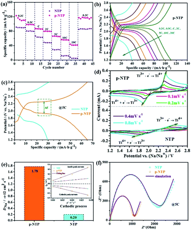
Fig. 4a is the rate performance of as-prepared materials, showing that p-NTP NPs electrode has a higher specific capacity at low current density (0.2C); with increasing the current density, its superiority of the rate performance is reflected. While the current rate increases from 0.2 to 0.5, 1.0, 2.0, 5.0 and 10C, the discharge capacity of p-NTP NPs electrode slightly decreases from 110.3 to 98.1, 86.1, 79.4, 65.3 and 55.5 mA h g−1 gradually, which are comparable to the related literatures,20,21 largely higher than those of NTP powders, further indicating its excellent rate performance. In particular, even at an ultrahigh current density of 20C, its discharge capacity is still 41.6 mA h g−1, and after long cycles with different rates, when the rate is reverted to 0.2C, the full capacity can still retain its original value. The plateau voltages shift subtly as the charge/discharge currents increase from 0.1 to 10C, implying an exceptional sodium ions storage capability for p-NTP NPs electrode (Fig. 4b). These drastic performance differences are visualized using charge–discharge profiles of the tested electrodes at 5C, as displayed in Fig. 4c. It is evident that the discharge plateaus of NTP electrode start turn to a short and fast drop at the current rate of 5C, while the electrodes of p-NTP electrode still generate a distinct, long and slow (dis)charge voltage plateau. In order to trace the change of structures and morphologies of the electrodes (p-NTP NPs and NTP powders), XRD (Fig. S5†), SEM (Fig. S6†) and TEM (Fig. S7†) were conducted before and after the cycles. As shown in Fig. S5,† the two materials can still retrieve the NTP phase after the cycles, which can also be demonstrated by HRTEM images (Fig. S7b and d†), but the degree of crystallinity has been reduced. The peak intensity of the (116) crystal face of NTP powders is lower than that of p-NTP NPs, implying that the latter has better structural stability under cycling. In addition, after the cycles, both the samples contain some large particles due to the aggregation of the crystals. However, compared with NTP powders, the electrode of p-NTP NPs displays more uniform distribution and smaller size (Fig. S6 and S7†). Fig. 4d displays the CV behaviours of two samples at various scanning rates in a voltage range between 1.2 and 2.8 V. A single pair of well-defined sharp redox peaks at 2.00 (red.) and 2.26 V (ox.) (vs. Na/Na+) for all scan rates is observed. The calculated peak areas can be used to estimate the ion reversible capacity, showing that NTP electrode has a lower sodium ion reversible storage capacity, which are quite consistent with the results obtained in Fig. 4a. Furthermore, the peak current and area of the peaks rise with increased scanning rates, as well as the anodic and cathodic peak potentials move to more negative and more positive, respectively. Even at a high scanning rate of 0.8 mV s−1, the very well-defined sharp redox reaction peaks are still maintained, indicating good electrode kinetics for sodium intercalation and de-intercalation. The pair of CV peaks could be attributed to the redox reaction of Ti4+/Ti3+, clearly revealing the nature of a reversible insertion–extraction reaction of Na+ in the NTP lattice, as depicted by the following equation:14,20.The sodium ion diffusion coefficient can be estimated from redox peak current and scan rate. As shown in Fig. 4e (the inset image), the redox peak current vs. the square root of the scan rate has a linear relationship with the square root of the scan rate, indicating a Na-ion diffusion-controlled electrode process, which can be expressed as:23,24
| ip = 2.69 × 10⁵An3/2C0D1/2υ1/2 |
Electrochemical kinetics
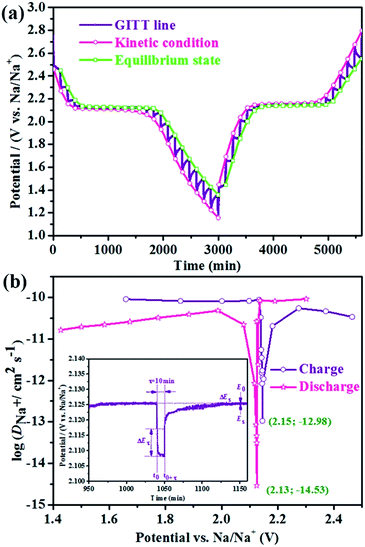
Based on the similar reaction mechanism of lithium- and sodium-ion batteries, we have employed the GITT to determine the DNa+ in p-NTP NPs electrode under charging and discharging between 1.2 and 2.8 V. Fig. 5a shows the GITT curve of p-NTP NPs electrode as a function of time, and the corresponding single titrations are separately demonstrated in Fig. 5b. On the basis of GITT measurement, the DNa+ can be calculated by the following equations:25where VM is the molar volume of NTP, which is 136.59 cm3 mol−1 deduced from the crystallographic data, mB and MB are the mass and the molecular weight of the electrode material, respectively, A is the surface area of the electrode, τ is the titration time, and ΔEs is the difference of the two consequent stabilized open-circuit potentials.
Based on the above equations, the DNa+ values calculated from GITT curve as a function of voltage during discharge and charge processes are labeled in Fig. 5b. Apparently, the DNa+ shows a minimum value at the end of the two phase region during both discharge and charge processes, of which the great change of the DNa+ is ascribed to the fact that Na+ diffusion could occur through the phase boundary and within each phase accompanied by strong interactions with other surrounding ions.26 Moreover, the DNa+ values show relative stability around 10−11 cm2 s−1 for both charge and discharge processes in the single-phase region.
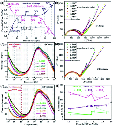
Furthermore, in order to verify and probe the variation of DNa+ and impedance in the process of charging and discharging, the different states of charge (SOC) and depths of discharge (DOD) of p-NTP NPs anode during the fourth cycle at 0.2C are shown in Fig. 6a, at which the EIS tests are conducted. Fig. 6b and d present the Nyquist plots at different SOC and DOD, respectively, and the corresponding Bode plots are shown in Fig. 6c and e, respectively. From the Bode plots, on the one hand, we can see that all the curves have two constants, namely, all Nyquist plots are composed of a small semicircle at high frequency probably connected with interface contact or bulk impedance, a large semicircle at high-to-medium frequency associated with the charge transfer reaction at the anode/electrolyte interface and a straight sloping line at low frequency related with the Na+ diffusion in the electrode material. On the other hand, we can qualitatively estimate the DNa+ in the electrodes by comparing the magnitude of the phase angle in the low frequency region (below 1 Hz) in the light of relevant report,27 namely, the smaller the phase angle, the faster the Na+ diffusion. Obviously, the phase angle show a maximum value in the two-phase region, however, that of the minimum value is obtained at the cut-off voltage during both discharge and charge processes, indicating that the DNa+ has the lowest value in the two phase region, which is consistent with the GITT results. To explore the variation of impedance, all Nyquist plots are fitted based upon the simplified equivalent circuit (inset in Fig. 6a), in which Rct stands for the charge transfer resistance, and other components Rs, CPE, Re, and W represent the total resistance of electrolyte, constant phase-angle element, diffusion resistance of Na-ions through the interface and Warburg impedance, respectively. The fitted results are displayed in Fig. 6f, which show that the change trends of impedance are similar whether the charge or discharge. All the impedance become larger to a different extent in the two-phase region. In view of the above, we can speculate that the low activity of the two-phase region is the kinetic limiting factor of p-NTP NPs.
Conclusions
In summary, a facile polyol assisted pyro-synthetic reaction coupled with following calcination is used to fabricate p-NTP NPs, in which the polyol plays multifunctional role as a solvent, reducing agent, carbon source and a low-cost fuel to facilitate a combustion process for a fast nucleation process. The specific surface area and pore size distribution of the as-obtained nanoparticles significantly reached 110.787 m2 g−1 and ∼2 nm, respectively, which undoubtedly provide more interface area between the active materials and the electrolyte. When tested for Na-insertion properties in the potential windows of 1.2–2.8 V, the fabricated p-NTP NPs anode demonstrates better performance than that of NTP powders, of which the excellent electrochemical performance is mainly attributed to more uniform particle distribution, better structural stability and conductivity, higher specific surface area as well as finer crystallinity and faster DNa+. Both the GITT and EIS results show that the DNa+ presents a minimum value at the end of the two-phase region in the p-NTP electrode. More importantly, the pyro-synthetic approach developed here might open avenues to promising materials for advanced SIBs for high performance large-scale energy storage devices.Acknowledgements
This work is financially supported by Chongqing Key Laboratory for Advanced Materials and Technologies of Clean Energies under cstc2011pt-sy90001, Start-up grant under SWU111071 from Southwest University and Chongqing Science and Technology Commission under cstc2012gjhz90002 and cstc2015jcyjA50031. The work is also supported by grants from Fundamental Research Funds for the Central Universities (SWU113079, XDJK2014C051) and Program for the Youth Talent in Science and Technology of Chongqing (cstc2014kjrc-qnrc50006) and Y. B. Niu would like to thank the support from the Graduate student research innovation project in Chongqing (CYB2015053).Notes and references
- S. Li, Y. Dong, L. Xu, X. Xu, L. He and L. Mai, Adv. Mater., 2014, 26, 3545–3553 CrossRef CAS PubMed.
- W. Huang, B. Li, M. F. Saleem, X. Wu, J. Li, J. Lin, D. Xia, W. Chu and Z. Wu, Chem.–Eur. J., 2014, 21, 851–860 CrossRef PubMed.
- Y. Zhu, Y. Xu, Y. Liu, C. Luo and C. Wang, Nanoscale, 2013, 5, 780–787 RSC.
- X. Wu, J. Zheng, Z. Gong and Y. Yang, J. Mater. Chem., 2011, 21, 18630–18637 RSC.
- Y.-U. Park, D.-H. Seo, H. Kim, J. Kim, S. Lee, B. Kim and K. Kang, Adv. Funct. Mater., 2014, 24, 4603–4614 CrossRef CAS.
- M. Xu, L. Wang, X. Zhao, J. Song, H. Xie, Y. Lu and J. B. Goodenough, Phys. Chem. Chem. Phys., 2013, 15, 13032–13037 RSC.
- T. Ramireddy, M. M. Rahman, N. Sharma, A. M. Glushenkov and Y. Chen, J. Power Sources, 2014, 271, 497–503 CrossRef CAS.
- B. Lin, S. Zhang and C. Deng, J. Mater. Chem. A, 2016, 4, 2550–2559 CAS.
- Y. Niu, M. Xu, C. Cheng, S. Bao, J. Hou, S. Liu, F. Yi, H. He and C. M. Li, J. Mater. Chem. A, 2015, 3, 17224–17229 CAS.
- Y. Niu, M. Xu, S.-J. Bao and C. M. Li, Chem. Commun., 2015, 51, 13120–13122 RSC.
- C. Masquelier and L. Croguennec, Chem. Rev., 2013, 113, 6552–6591 CrossRef CAS PubMed.
- D. Wang, Q. Liu, C. Chen, M. Li, X. Meng, X. Bie, Y. Wei, Y. Huang, F. Du, C. Wang and G. Chen, ACS Appl. Mater. Interfaces, 2015, 8, 2238–2246 Search PubMed.
- C. Wu, P. Kopold, Y.-L. Ding, P. A. van Aken, J. Maier and Y. Yu, ACS Nano, 2015, 9, 6610–6618 CrossRef CAS PubMed.
- G. Pang, C. Yuan, P. Nie, B. Ding, J. Zhu and X. Zhang, Nanoscale, 2014, 6, 6328–6334 RSC.
- J. Yang, H. Wang, P. Hu, J. Qi, L. Guo and L. Wang, Small, 2015, 11, 3744–3749 CrossRef CAS PubMed.
- B. Zhao, Q. Wang, S. Zhang and C. Deng, J. Mater. Chem. A, 2015, 3, 12089–12096 CAS.
- B. Zhao, B. Lin, S. Zhang and C. Deng, Nanoscale, 2015, 7, 18552–18560 RSC.
- M. Vujković, M. Mitrić and S. Mentus, J. Power Sources, 2015, 288, 176–186 CrossRef.
- Y. Jiang, L. Zeng, J. Wang, W. Li, F. Pan and Y. Yu, Nanoscale, 2015, 7, 14723–14729 RSC.
- G. Pang, P. Nie, C. Yuan, L. Shen, X. Zhang, H. Li and C. Zhang, J. Mater. Chem. A, 2014, 2, 20659–20666 CAS.
- G. Yang, H. Song, M. Wu and C. Wang, J. Mater. Chem. A, 2015, 3, 18718–18726 CAS.
- J. Gim, V. Mathew, J. Lim, J. Song, S. Baek, J. Kang, D. Ahn, S.-J. Song, H. Yoon and J. Kim, Sci. Rep., 2012, 2, 1–6 Search PubMed.
- C. Deng, S. Zhang and Y. Wu, Nanoscale, 2015, 7, 487–491 RSC.
- H. Wang, D. Jiang, Y. Zhang, G. Li, X. Lan, H. Zhong, Z. Zhang and Y. Jiang, Electrochim. Acta, 2015, 155, 23–28 CrossRef CAS.
- K. M. Shaju, G. V. Subba Rao and B. V. R. Chowdari, Electrochim. Acta, 2003, 48, 2691–2703 CrossRef CAS.
- J. Wang, X. Li, Z. Wang, H. Guo, B. Huang, Z. Wang and G. Yan, J. Solid State Electrochem., 2014, 19, 153–160 CrossRef.
- X. Zhou, G. Wu, J. Wu, H. Yang, J. Wang and G. Gao, Phys. Chem. Chem. Phys., 2014, 16, 3973–3982 RSC.
Footnote |
| † Electronic supplementary information (ESI) available. See DOI: 10.1039/c6ra06533c |
| This journal is © The Royal Society of Chemistry 2016 |

