DOI:
10.1039/C6RA20004D
(Paper)
RSC Adv., 2016,
6, 96296-96305
Tuning porous nanostructures of MnCo2O4 for application in supercapacitors and catalysis†
Received
8th August 2016
, Accepted 2nd October 2016
First published on 3rd October 2016
Abstract
It is shown that spinel type MnCo2O4 can be used as a pure negative electrode in supercapacitors. The electrochemical response can be significantly tuned by forming and modulating the mesoporous structures of these materials. With varying formation temperature, the nature of particle growth mechanism moves from Oswald ripening type to digestive ripening. This leads to increased surface area, porosity and charged states on the particles surface. Thus, making this material useful from application ranging from supercapacitors to catalysis. As a function of changing porosity, specific capacitance could be tuned in the range ∼290 F g−1. Added functionality of the material could be established by proving its excellent catalytic response for reducing p-nitrophenol, a common pollutant found in industrial waste streams. The sample calcined at 800 °C reduced p-nitrophenol in 8 min at 1 mg mL−1 catalyst concentration, while the sample obtained at 400 °C could complete the task only after 16 min. The superior catalytic response have been explained by analyzing the change in zeta potential, which develops on the surface of different porous structures.
Introduction
Amongst energy storage technologies, which are synergistically contributing in maintaining energy security, Li-batteries and supercapacitors are two of the most important.1–3 While the batteries have high energy densities, the supercapacitors return high power density. Supercapacitors, owing to their high power and cycle life, are also bridging the gap between the conventional capacitors and batteries/fuel cells.4,5 Over the last few years, design and fabrication of novel electrode materials have led to significant improvement in the supercapacitor performance.6 Supercapacitors with newer device configuration or modified electrolytes have also been proposed recently.7,8
Nanostructures of many transition metal oxides, with high electrochemical performance, have become intrinsic for the development of next generation high-energy supercapacitors.9–12 The flexibility to tune the size, orientation, morphology and associated electrochemical properties of such nanostructures is the driving force behind the continuing interest. But, most simple nano metal oxides are continuously facing competition from enhanced electrochemical performance, which is being reported in new forms of carbon or even the conducting polymeric systems.13,14 In recent times, complex spinel type metal oxides (AB2O4) have evolved as efficient, effective and scalable electrode materials.15,16 These oxides have been found to have high electrical conductivity, tunable oxidation states, low cost and environmental friendliness, when compared to many other simpler metal oxides.17,18
MnCo2O4 is one such interesting metal cobaltite, which has been proposed as electrode material for supercapacitors.19,20 To make MnCo2O4 economically viable, low cost synthesis protocols are required. In addition, tailoring their nanostructures while maintaining higher conductivity and surface area remain challenging.21,22 An interesting strategy for meeting these targets can be based on the stabilization of hierarchical or mesoporous structure.23–26 The hierarchical porous nanostructures can bring higher surface area, which ensure efficient intercalation of liquid/aqueous electrolyte, while ensuring additional electroactive sites for faradaic redox reactions.27,28 The porous structure, if stable, allow transport channels for ions (or electrons), control the volume distortions during cycling and thereby improve the cycle life.29
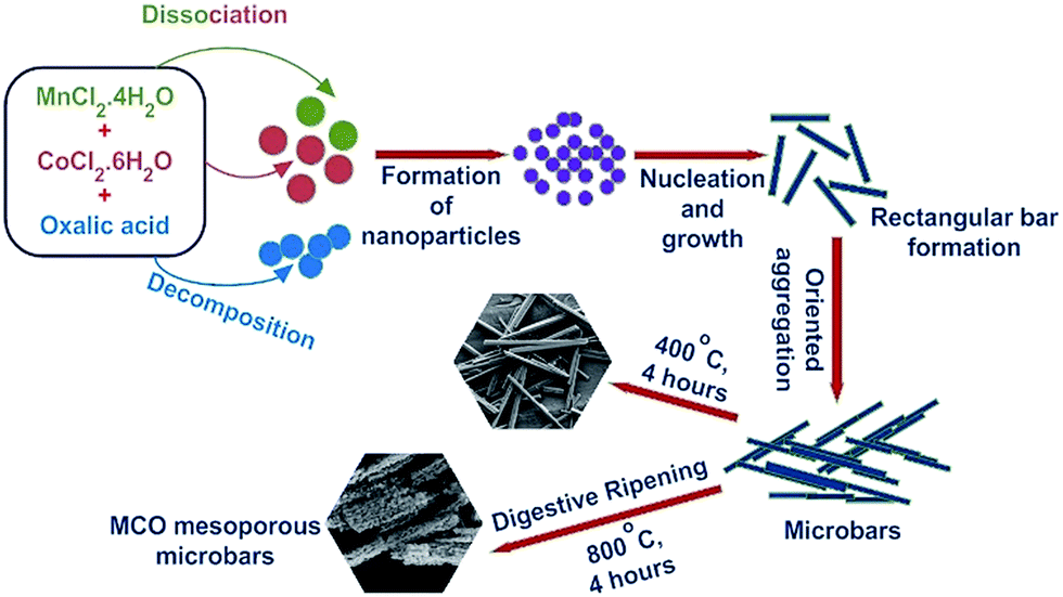
In this paper, we present a simple synthetic strategy for large scale production of porous nanostructures of crystalline spinel type MnCo2O4 (MCO). The particle growth mechanism is explained using the inverse Ostwald ripening process. The usefulness of the synthesized porous MnCo2O4 becomes evident as it can be employed as an electrode material in asymmetric supercapacitors. Contrary to earlier reports, it is shown that the material can be employed as a pure negative electrode. Therefore, if combined with other suitable positive electrode, the operational window of supercapacitors can be significantly enhanced. The porous structures can also lead to increased active surface states. This feature can be immediately be used in application such as catalysis.30 The enhanced catalytic response is a direct consequence of the varying zeta potential on the surface of the particles.31 There are few preliminary reports on the use of solid MnCo2O4 as catalyst. In this study, we show that porous structures of MnCo2O4 can be utilised as important catalyst for reduction of p-nitrophenol – a common water pollutant find in industrial waste.32
Materials and method
Materials used
Oxalic acid (99%), cobalt chloride hexahydrate (98%), manganese chloride hexahydrate (99%) and sodium borohydride (95%) were purchased from Merck Specialities Pvt. Ltd. (India). p-Nitrophenol (98%) was procured from LobaChemie Pvt. Ltd. (India). All the precursors were used without further purification.
Synthesis of MnCo2O4 microbars
Mn1/3Co2/3C2O4·2H2O solid solution was first prepared following the co-precipitation method.33 For this, CoCl2·6H2O and MnCl2·4H2O solutions, in molar ratio 2![[thin space (1/6-em)]](https://www.rsc.org/images/entities/char_2009.gif) :1, were mixed and then added drop-wise to a pre-heated 0.4 M oxalic acid (in 50% excess). The resultant precipitate was left undisturbed for 24 h, under ambient conditions. The precipitate was subsequently filtered and washed several times with de-ionized water and ethanol, to ensure removal of Cl− and excess oxalic acid. The filtrate was dried in an oven at 90 °C for 8 h. The final product was obtained after calcining the powder at 400 °C (MCO-400) and 800 °C (MCO-800) for 4 h in air.
:1, were mixed and then added drop-wise to a pre-heated 0.4 M oxalic acid (in 50% excess). The resultant precipitate was left undisturbed for 24 h, under ambient conditions. The precipitate was subsequently filtered and washed several times with de-ionized water and ethanol, to ensure removal of Cl− and excess oxalic acid. The filtrate was dried in an oven at 90 °C for 8 h. The final product was obtained after calcining the powder at 400 °C (MCO-400) and 800 °C (MCO-800) for 4 h in air.
Materials characterization
The phase formation of the samples was confirmed by the analysis of X-ray diffraction data collected using a PANalytical X'Pert diffractometer with CuKα incident radiation (λ = 0.15406 nm) and in the 2θ range 10–80°. Scanning electron (SEM CARL ZEISS SUPRA 40, 20 kV), transmission electron microscopy (TEM FEI-TECNAI G220S-Twin operated at 200 kV) and high resolution TEM (JEOL JEM-2100) were used for investigating the particle shape, size and morphology. X-ray photoelectron spectroscopy (XPS) measurements data was obtained using a PHI-5000 VERSAProbe II X-ray photoelectron spectrometer that had monochromatic Al Kα as the incident photon energy. Thermogravimetric analysis (TGA) was performed under air with heating rate of 10 °C min−1 using a PerkinElmer Diamond TG/DTA thermal analyzer. The Brunauer–Emmett–Teller (BET) surface area and porosity were measured with a Quantachrome Autosorb-iQ/MP-XR surface area analyzer. The UV-vis absorption spectra were recorded on UV-vis spectrophotometer (Avantes Starline AvaSpec-ULS3648). The particle size distribution and zeta potential were obtained from Horiba Scientific Nano Particle Analyzer SZ-100.
Electrochemical measurement
For the preparation of MnCo2O4 electrodes, 80 wt% of MnCo2O4, 10 wt% of activated carbon, and 10 wt% polyvinylidene fluoride were mixed using acetone as mixing media. The mixture was ultrasonicated and then stirred at 80 °C to obtain homogeneous slurry. The slurry was coated onto a graphite sheet (1 cm × 1 cm). A typical mass loading of the active electrode materials was kept at ∼0.3 mg cm−2. The electrochemical measurements such as cyclic voltammetry (CV), galvanostatic charge–discharge (GCD) and impedance spectroscopy (EIS) were performed using the Metrohm Autolab (PGSTAT302N) with three electrode cell configuration in 6 M KOH aqueous electrolyte. Platinum wire and Ag/AgCl/3.0 M KCl were used as the counter and reference electrodes, respectively. EIS measurements were performed in the frequency range from 0.01 Hz to 100 kHz.
Catalytic measurement
To investigate the performance of porous MnCo2O4 as a catalytic agent, 20 mL aqueous solution of p-nitrophenol (10−4 M) and 60 mg of NaBH4 (8 × 10⁻² M) were mixed initially. Subsequently, varying concentrations (i.e., 0.25, 0.5, or 1 mg mL−1) of MCO-400 and MCO-800 samples were added to the above mixture. Time dependent UV-Vis spectra were recorded in the range of 200–500 nm for catalytic investigations.
For explaining the catalytic process, the zeta potential (ζ) measurements were performed using the catalysts in the de-ionized water, while maintaining similar concentrations for the different types of particles used during the experiments.
Results and discussion
Morphological features, from simple to complex, may actually define the usefulness of a material in the kind of applications being reported in this paper. For most applications, the 3D nanostructures are proving beneficial, in comparison to their 0D, 1D or 2D nanostructure counterparts. The reasonably large 3D nanostructures: (a) are relatively more stable, (b) provide accessible channels for ion transport; leading to simulation of ion reservoir, (c) allow formation of effective electrode/electrolyte interface, (d) facilitates easier electrolyte ion diffusion that leads to the shorter diffusion path length, and (e) tends to have better connectivity, which consequently improves the electrical conductivity and the overall electrochemical performance.
Fig. S1† shows that the structure of Mn1/3Co2/3C2O4·2H2O complex comprised of solid rectangular bar shaped structures of length between 10–80 μm, and width between 1.25–1.45 μm. The complex could be converted into single phase MnCo2O4, when heated at calcination temperature ≥400 °C. Contrary to many other spinel ceramics, MnCo2O4 actually showed stabilization of porous structures with changing calcination temperature in the range 400–800 °C. Similar, morphologies have been reported in few earlier reports.34 Fig. 1(a) and (b) shows the SEM micrographs observed for MCO-400 and MCO-800, respectively. The sample retained similar morphology up to temperatures T ∼ 400 °C. As the calcination temperature increased to 800 °C, small nanoparticles started to form at the surface of underlying solid rectangular bars. The particle growth mechanism can be explained using the digestive ripening mechanism shown in Fig. 2. During digestive ripening, the electrostatic energy of charged particles acts as a complementing force alongside the curvature effect.35 The micrographs clearly indicated the stabilization of porous microstructure.
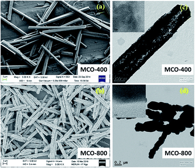 |
| | Fig. 1 SEM images of (a) MCO-400 and (b) MCO-800; TEM and SAED images (insets) of (c) MCO-400 (d) MCO-800. | |
 |
| | Fig. 2 Schematic illustration of the growth mechanism of the MnCo2O4 microbars. | |
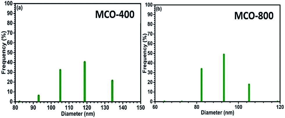
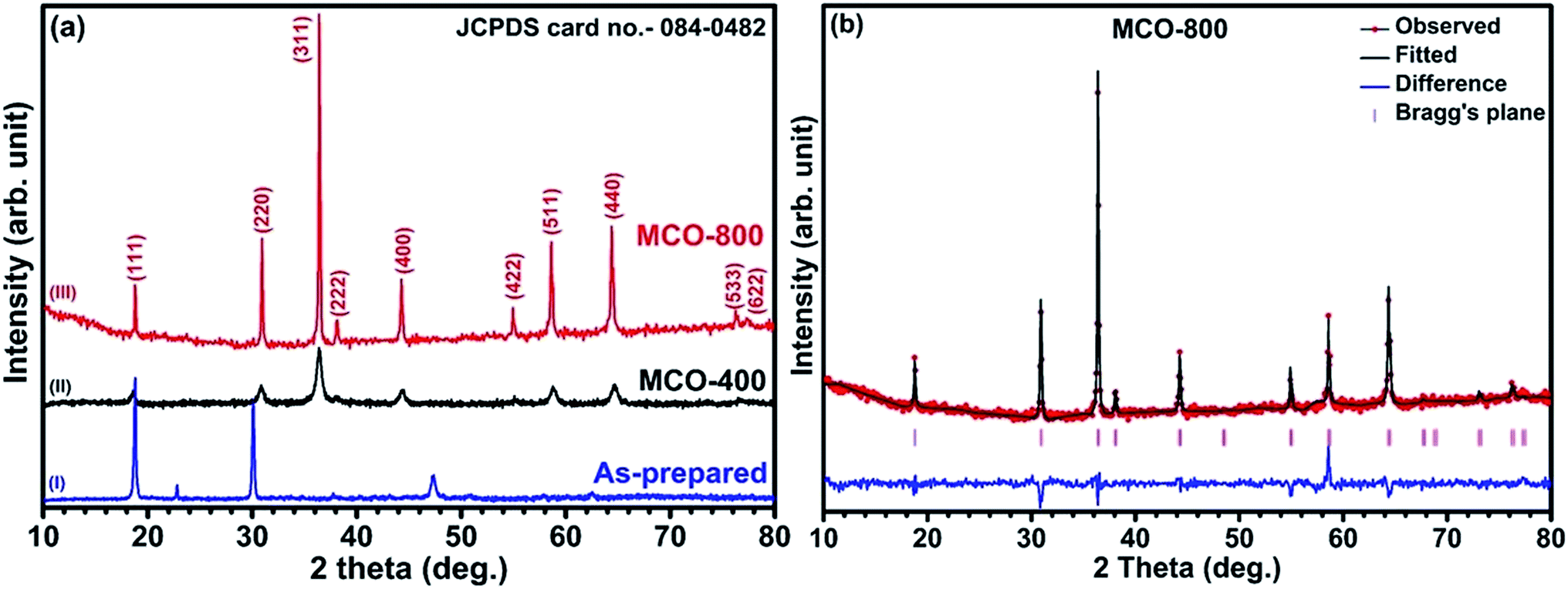
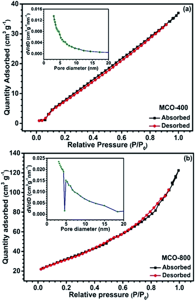
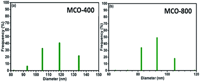
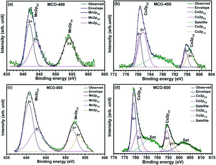
Understanding the nitrogen adsorption–desorption isotherms gives the insight about the nature of pores and pore size distribution in nanomaterials. As shown in Fig. 3(a) and (b). MCO-400 and MCO-800 both displayed type IV isotherms with distinctive hysteresis loop between P/P0 = 0.4 to 1, and BET surface areas ∼54 and ∼118 m2 g−1, respectively. The pore size distribution curves indicated the presence of mesoporosity with majority of small mesopores, in both the samples. The changes in the size of particles were evaluated using the analysis of Dynamic Light Scattering (DLS) data. The obtained particle size distributions are depicted in Fig. 4(a) and (b), which shows average particle size of MCO-400 was ∼109 nm while, for MCO-800 it was ∼86.1 nm. It is also important to check that increased porosity does not lead to amorphosity, which can introduce serious detrimental effects in oxide systems.36 The retentivity of the crystalline character was confirmed by investigating the selected area electron diffraction (SAED) and X-ray diffraction patterns of MCO-400 and MCO-800 samples. The SAED patterns, shown in insets of Fig. S9(b) and (e),† displayed distinct lattice fringes, with interplanar spacings corresponding to different planes of the MnCo2O4 crystal and confirming the retention of crystalline nature. Additionally, high resolution TEM micrographs with fringe patterns for both MCO-400 and MCO-800 samples are given in the ESI as Fig. S9.† The XRD patterns of the uncalcined and calcined samples are shown in Fig. 5(a). All the diffraction peaks could be indexed using the cubic spinel unit cell with space group Fd![[3 with combining macron]](https://www.rsc.org/images/entities/char_0033_0304.gif) m (227), according to JCPDS card no. 084-0482. The Rietveld refinement of X-ray diffraction data of MCO-800, using the space group Fdm, is shown in Fig. 5(b). The lattice parameter obtained from the refinement was ∼8.183 ± 0.006 Å. Schematic view of a typical MnCo2O4 spinel unit cell is shown in Fig. S2.† XPS analysis was performed to investigate the composition and valence of the elements of the as-synthesized powder. All of the binding energies were corrected for specimen changing by referring them to the C 1s peak (284.6 eV). As seen in Fig. 6, the Co 2p3/2 binding energy was 780.1 eV. This indicated coexistence of +2 and +3 of Co. The Mn 2p3/2 binding energy was located at 642.1 eV. This indicated coexistence of Mn2+, Mn3+ along with Mn4+ Mn3O4.
m (227), according to JCPDS card no. 084-0482. The Rietveld refinement of X-ray diffraction data of MCO-800, using the space group Fdm, is shown in Fig. 5(b). The lattice parameter obtained from the refinement was ∼8.183 ± 0.006 Å. Schematic view of a typical MnCo2O4 spinel unit cell is shown in Fig. S2.† XPS analysis was performed to investigate the composition and valence of the elements of the as-synthesized powder. All of the binding energies were corrected for specimen changing by referring them to the C 1s peak (284.6 eV). As seen in Fig. 6, the Co 2p3/2 binding energy was 780.1 eV. This indicated coexistence of +2 and +3 of Co. The Mn 2p3/2 binding energy was located at 642.1 eV. This indicated coexistence of Mn2+, Mn3+ along with Mn4+ Mn3O4.
 |
| | Fig. 3 Nitrogen adsorption/desorption isotherms of (a) MCO-400 and (b) MCO-800 and (insets) corresponding BJH pore size distribution. | |
 |
| | Fig. 4 Particle size distribution of spinel oxides (a) MCO-400 and (b) MCO-800 in water. | |
 |
| | Fig. 5 (a) XRD patterns of MnCo2O4 (I) as-prepared and calcined at (II) 400 °C and (III) 800 °C (b) Rietveld refinement of MnCo2O4 spinel and (inset) a unit cell structural design of MnCo2O4 spinel from refinement data. | |
 |
| | Fig. 6 XPS spectrums of (a) Mn, (b) Co in MCO-400 and (c) Mn, (d) Co in MCO-800. | |
Applications of porous MnCo2O4
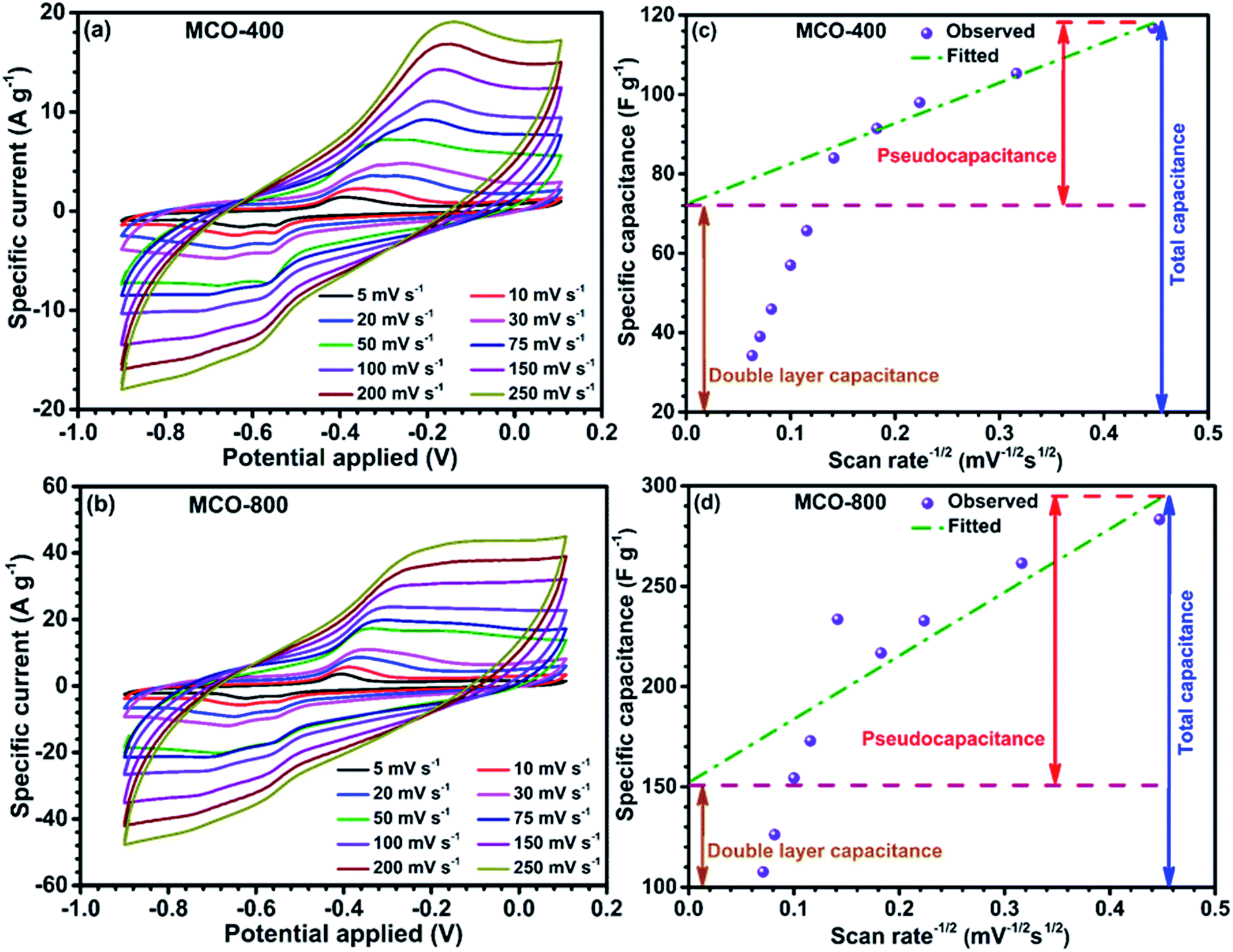
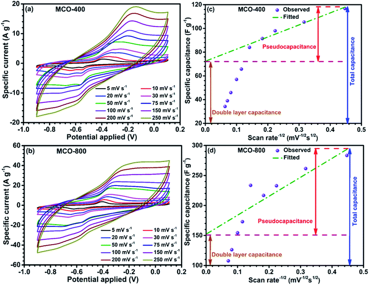
Negative electrode in electrochemical systems. Following the preliminary characterization, the electrochemical performance of the MCO-800 and MCO-400 was evaluated using the cyclic voltammetry and galvanostatic charge–discharge techniques. The detailed plots related to CV and GCD are shown in Fig. 7 and 8, respectively. Well-defined redox peaks were clearly visible in the two voltammograms of MCO-400 and MCO-800, in a potential window of −0.9 to 0.1 V. This voltage window was stable for both these types of MCO used, with no dissolution problem or evolution of H2/O2 gases.
 |
| | Fig. 7 CV curves of (a) MCO-400 and (b) MCO-800 at different scan rates; quantification of double-layer and pseudocapacitance for (c) MCO-400 and (d) MCO-800. | |
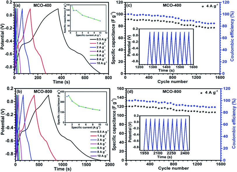 |
| | Fig. 8 Galvanostatic charging–discharging profile of (a) MCO-400 and (b) MCO-800 at different specific currents and (insets) specific current dependence of the specific capacitance for (a) MCO-400 and (b) MCO-800; cyclic stability of the spinel electrodes (c) MCO-400 and (d) MCO-800 over 1500 cycles and insets show the continuous last 10 cycles of charge/discharge at 4 A g−1. | |
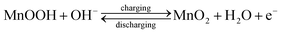
Proper selection of stable voltage range is also crucial for better cycling performance.37,38 The CV data indicated that specific capacitance was the convolution of double-layer and faradic capacitance. At higher scan rates, the redox current increases with the anodic/cathodic peak shifting toward the positive/negative potential, respectively. This could be attributed to the kinetic irreversibility in the redox process, due to polarization and ohmic resistance. The possible redox peaks of the electrode materials are given below:39,40
| |
 | (1) |
| |
 | (2) |
The reduction of Mn4+ → Mn3+, in addition to the Co3+ reduction peak, during the cathodic sweep was also observed in both the samples.41,42 The average specific capacitance was evaluated from the CV curves using the equation:43
| |
 | (3) |
where
m is the mass of the active material,
ν is the scan rate, Δ
V indicates the potential window, and
i(
V) is the current at each potential. The obtained maximum specific capacitance values for MCO-400 and MCO-800 samples, at 5 mV s
−1 scan rate, were ∼117 and ∼284 F g
−1, respectively. High specific capacitance of the MCO-800 sample could be attributed to the formation of large interfacial contact region between the electrode and electrolyte. The surface and bulk contribution in the total specific capacitance (SC) of the samples were estimated by using the relation given below:
44| | |
SC = SC(bulk) + SC(surface)
| (4) |
SC(bulk) occurs due to faradic reactions, and/or diffusion of the electrolyte ions inside the bulk of the material whereas SC(surface) originates due to the physisorption of the electrolyte ions. When the scan rate tends to infinity (ν−1/2 → 0), the total specific capacitance is only due to surface of the electrode material, since the process associated with SC(bulk) are hindered at higher scan rates.45 Fig. 7(c) and (d) shows the variation of specific capacitance with respect to inverse of square root of scan rates for samples MCO-400 and MCO-800, respectively. The specific capacitance varies linearly with respect to ν−1/2 at lower scan rates. In contrast, at higher scan rates, linear nature seems to behave abruptly because available electroactive sites are not utilized effectively. The intercept of fitted lines at y-axis provides the EDLC contribution in the estimation of the specific capacitance. This was ∼61% and ∼51% for MCO-400 and MCO-800, respectively. The higher bulk contribution in MCO-800 could be due to the induced mesoporosity into the sample at elevated calcination temperatures. Additionally, CV studies for the both samples were also carried out at 3 times higher mass loading of about ∼1.1 mg cm−2. CV profiles and variation of specific capacitance with respect to inverse of square root of scan rates for both samples MCO-400 and MCO-800 are depicted in Fig. S10 of ESI.† The estimated specific capacitance values for MCO-400 and MCO-800 samples were found to be ∼108 and ∼271 F g−1 at scan rate of 5 mV s−1, respectively. Very interestingly, the obtained values showed that the sample retain nearly the same specific capacitance value at higher mass loading. This makes the material even more useful for industries.
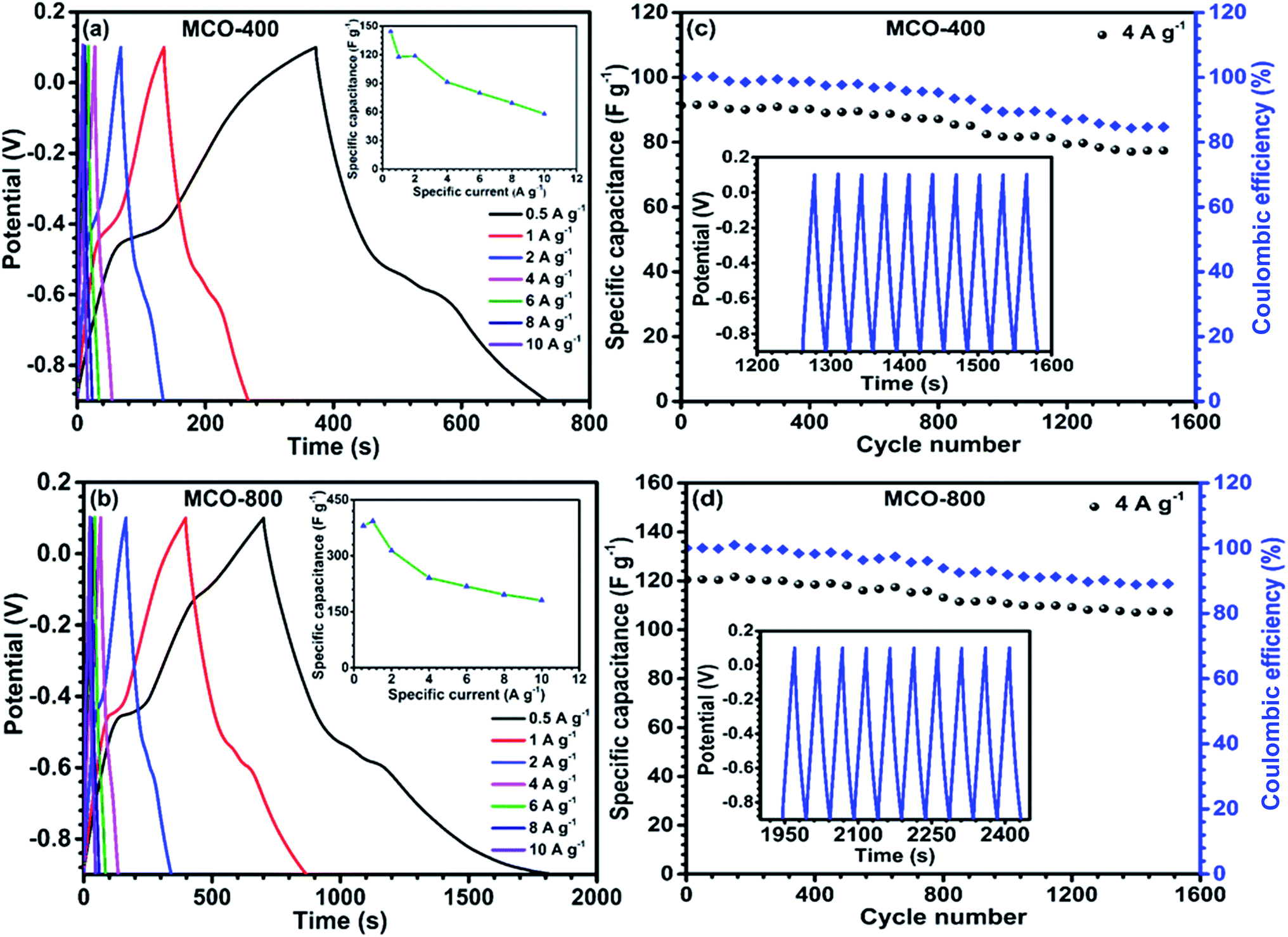
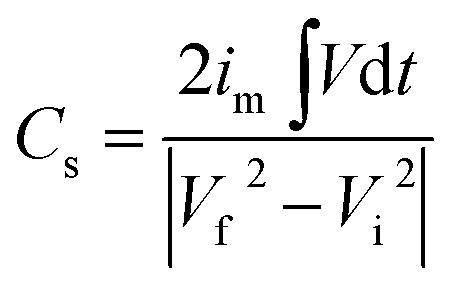
Galvanostatic charge discharge curves, at different specific currents were obtained using chronopotentiometry technique. The curves are depicted in Fig. 8(a) and (b). The non-linear nature of GCD profiles further supported the observations from the CV curves that the charge separation from EDLC and redox processes both add to specific capacitance. The non-linear nature of these charge–discharge profiles confirmed the presence of pseudocapacitance, whereas the linear behaviour of charge–discharge curve is a characteristics of EDLC. Explicitly, the EDLC coming due to the charge separation between the electrolyte/electrode interfaces is dominated in the range −0.5 V to 0.1 V whereas in the portion −0.9 V to −0.5 V, the redox reactions manifest the contribution toward specific capacitance. The specific capacitance values from the charge discharge curves could be calculated using following relation:46
| |
 | (5) |
where
im is specific current,
Vd
t is area under discharging curve and
Vf,
Vi are final and initial voltage. The maximum specific capacitance for MCO-400 was found to be ∼144 F g
−1 and ∼118 F g
−1 at 0.5 A g
−1 and 1 A g
−1 specific currents, respectively. In comparison, MCO-800 sample showed much higher specific capacitance of ∼392 F g
−1 at 1 A g
−1. Inset to
Fig. 8(a) and (b) represents the variation of specific capacitance with charging–discharging currents. At higher specific currents, specific capacitance reduces due to underutilization of the inner bulk of the electrodes. The increased specific capacitance in MCO-800 is largely attributed to the mesoporosity induced in the micro-sized rectangular bars. This resulted in relatively higher surface area and electroactive linkages, which can offer more reaction sites to the electrolyte ions. Further, much improved diffusion after cycling can lead to an increase in the wettability of surface of the pores of electrode materials, which will simulate additional pathways for ions and electrolytes to intercalate. Similar to CV, GCD profiles were also plotted at higher mass loading of electrode, which are shown in Fig. S11 of ESI.
† The observed specific capacitance for MCO-400 returned values at ∼134 F g
−1 and ∼105 F g
−1 at 0.5 A g
−1 and 1 A g
−1 specific currents, respectively. In comparison, MCO-800 sample depicted much higher specific capacitance of ∼375 F g
−1 at 1 A g
−1.
Electrochemical stability of the samples was analyzed by the cyclic stability measurement at 4 A g−1 as given in Fig. 8(c) and (d). The MCO-400 retained 84% of the initial capacitance, after 1500 charge–discharge cycles. In comparison, MCO-800 showed capacitance retention of ∼89% over 1500 cycles. The decrease of specific capacitance during cycling is attributed to: (a) dissolution of Mn3+ in the electrolyte and (b) separation of the nanoparticles within the mesoporous structure of the electrodes.47
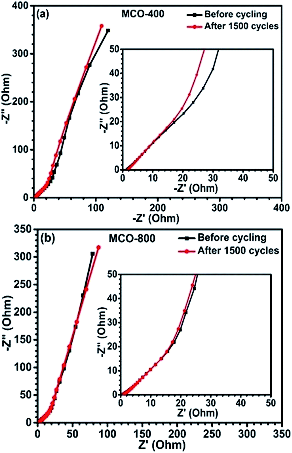
To further understand the charge transport and rate kinetics during electrochemical response of the electrodes, EIS was carried out. Fig. 9(a) and (b) depicts Nyquist plots (before and after cycling) for samples MCO-400 and MCO-800, respectively. The intersection of the Nyquist plot at x-axis is associated with the equivalent series resistance (ESR), which results from the electrodes, electrolytes and various contacts. The ESR of MCO-400 sample, before and after cycling was ∼1.42 Ω and ∼1.67 Ω, respectively. For MCO-800 sample, it was ∼0.85 Ω and ∼0.97 Ω, respectively. The relatively lower ESR values for MCO-800 allow higher rate capability and specific capacitance in this sample. The capacitance fade, in the present samples, can be attributed to the increase in the series resistance. The structures of both the samples show high stability and absence of any impurity phases. Therefore, these two factors can be ruled out during the explanation of capacitance fade.
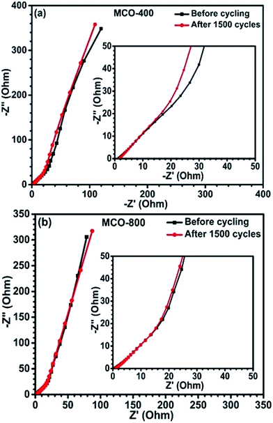 |
| | Fig. 9 Nyquist plots of the EIS for the spinel electrodes (a) MCO-400 and (b) MCO-800. | |
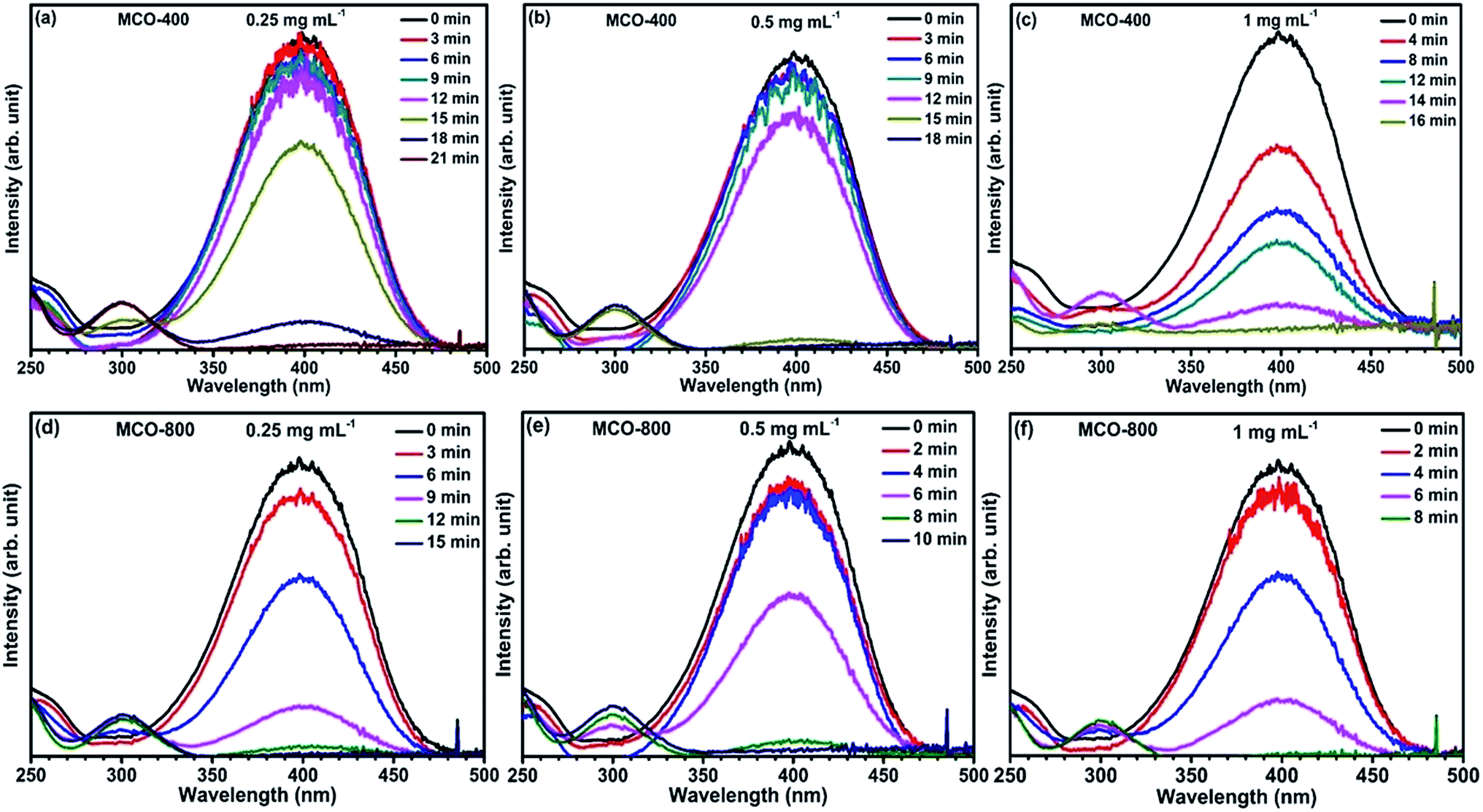
Reduction catalysis. Apart from the synergistic effect of binary metal oxides as electrode material for supercapacitor, these spinel type composite metal oxides containing 3d metal ions in multiple oxidation state, have also been investigated for catalytic reduction for many organic conversion reactions.48,49 The active surface area is recognized to have considerable effect on the catalytic properties of the materials.In this present work, the mesoporous MnCo2O4 microbars, synthesized at 400 °C and 800 °C, were examined as catalyst for the degradation of p-nitrophenol converting to p-aminophenol with assistance of NaBH4 (acts as reducing agent). The reaction was monitored by observing the disappearance of yellow color of p-NP and further analysis of the absorbance spectra by UV-vis spectrophotometry. Addition of NaBH4 in solid form directly to the p-NP solution, turns it from light to intense yellow color. This was also confirmed by the UV-vis spectrum where, the peak due to p-NP at 317 nm red shifted to 400 nm. This peak is linked to the formation of p-nitrophenolate ion in alkaline ambience. Subsequently, varying amounts of catalysts were added and tested by keeping the solution unstirred. This leads to the reduction in the absorbance peak at ∼400 nm and appearance of a new peak around ∼300 nm, which confirms the formation of p-AP. The time required to complete the conversion was recorded. It could be seen that, for fixed amount of p-NP and NaBH4, the time for completion of the conversion of p-NP to p-AP was related to the nature and the quantity of the catalyst added to the solution. Fig. 10(a–f) shows the catalytic activity of MCO-400 and MCO-800 and the change in the decolorization period with respect to the quantity of the catalyst (Table 1).
 |
| | Fig. 10 (a–c) UV-vis absorption spectra of p-NP reduction with NaBH4 catalyzed by different concentrations of MCO-400 and (d–f) for different concentrations of MCO-800. | |
Table 1 Essence of the catalytic activity of samples MCO-400 and MCO-800 for the reduction of p-NP with NaBH4
| Spinel samples |
Decolorization time (min) |
| 0.25 mg mL−1 |
0.50 mg mL−1 |
1.00 mg mL−1 |
| MCO-400 |
21 |
18 |
16 |
| MCO-800 |
15 |
10 |
8 |
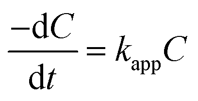
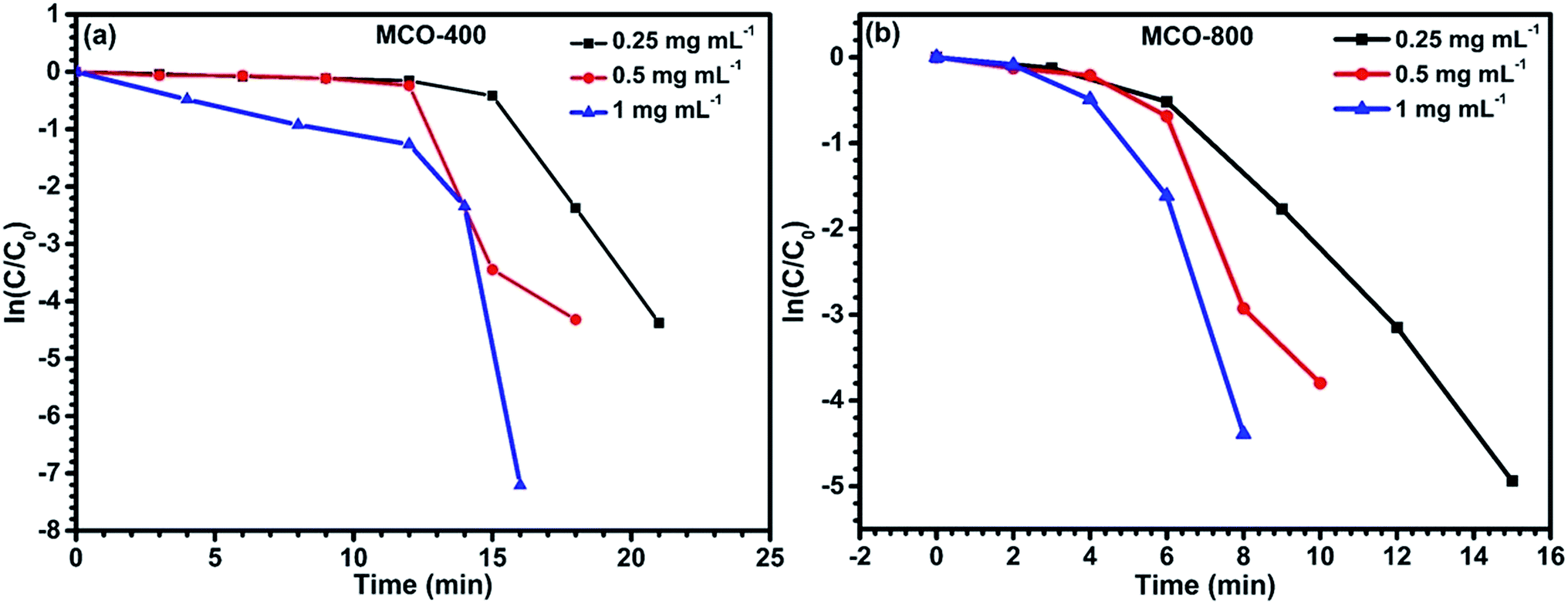
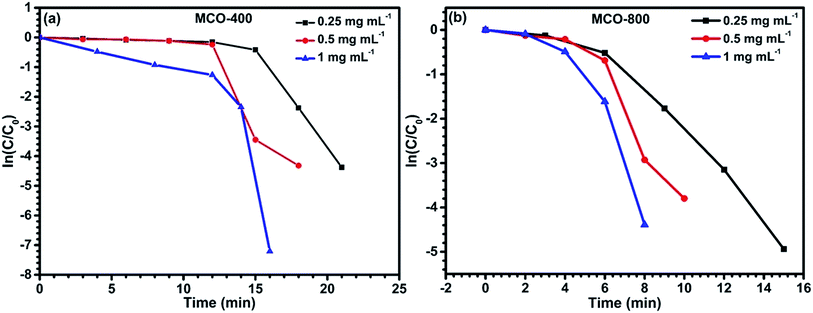
Incorporating the Beer–Lambert's law, the absorbance is proportional to the concentration of the absorber.50 Therefore, the value of C/C0 is equal to that of A/A0, where C0 and A0 are the original concentration and absorbance of p-nitrophenolate, whereas C and A are the concentration and absorbance of p-nitrophenolate at any time during the reaction, respectively. Concentration of NaBH4 was kept sufficiently high in comparison to p-nitrophenol in the overall solution so that the reaction follows the pseudo-first-order kinetics. Hence, the rate constant can be calculated via the following relations:
| |
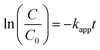 | (6) |
| |
 | (7) |
where
kapp is the apparent rate constant and
t is the reaction time. The linear correlation between ln(
C/
C0) and
t for all the concentration of MCO-400 and MCO-800 confirms that the reduction of 4-nitrophenol is a pseudo-first-order reaction. Plots of ln(
C/
C0)
versus time for the reduction of
p-NP into
p-AP is shown in
Fig. 12(a) and (b) for samples MCO-400 and MCO-800 indicated nearly linear correlation.
The catalytic results are a direct consequence of the spinel structure having ‘dn’ (n = 5–9, more than half-filled) electronic configuration, which facilitates fast reduction catalysis by supplying electrons from BH4− ions to the acceptor during absorption on the surface.51 Additionally, the presence of redox couples such as Co3+/Co2+ and/or Mn3+/Mn2+, during the preparation of MnCo2O4, can help in the electron transfer and act as electron relaying system in the donor–acceptor partner. To compare the catalytic activity of both the samples, the apparent rate values were estimated from Fig. 11 and are tabulated in Table 2.
 |
| | Fig. 11 Plots of ln(C/C0) vs. time for reduction catalyzed by (a) MCO-400 and (b) MCO-800 at different concentrations. | |
Table 2 Effect of the amount of catalyst materials on the reduction duration
| Concentration (mg mL−1) |
Rate constant (s−1) MCO-400 |
Rate constant (s−1) MCO-800 |
| 0.25 |
1.91 × 10⁻³ |
4.41 × 10⁻³ |
| 0.5 |
2.72 × 10⁻³ |
5.04 × 10⁻³ |
| 1 |
4.25 × 10⁻³ |
6.52 × 10⁻³ |
As the electropositivity of the surface increases, more OH− ions will get attracted towards the surface, leading to increase in the release of H+ ions in the solution.52 This will decrease the overall pH of the solution and shift the zeta potential towards the positive side.53 Zeta potential can be tuned by actively varying the surface states, which are linked to effective surface area. In case of MCO-400 and MCO-800, zeta potential values were −43.5 and −32.4 mV, respectively as shown in Fig. 12.
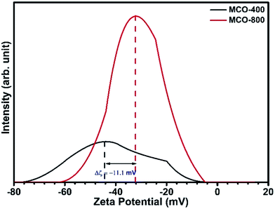 |
| | Fig. 12 Zeta potential curves for spinel oxides performed in water at 0.5 mg mL−1. | |
So, the less negative zeta potential values of MCO-800 with respect to MCO-400 indicated excess of surface positive charge sites in case of MCO-800. Hence, the better catalytic activity of MCO-800 is directly linked to the higher surface sites which would be available for the attachment of p-nitrophenolate and BH4− ions to the catalyst surface.
Conclusions
The synthesized MnCo2O4 nanostructures show applications ranging from supercapacitors to catalysis. The calcination of MnCo2O4 at higher temperature (800 °C) induces porosity and leads to higher specific surface area. The specific capacitance obtained in electrochemical measurements of MCO-400 and MCO-800 samples were ∼118 F g−1 and ∼392 F g−1, respectively at a constant specific current of 1 A g−1. The zeta potential developed on the surface of the porous particles enhances the surface interaction of catalyst with p-nitrophenolate and BH4− ions. This increases the catalytic reduction capability of the porous spinel materials.
Acknowledgements
The authors acknowledge IGSTC (DST, India) and MPG (Germany) for providing the financial support under the Max Planck Partner Group Program at IIT Kharagpur.
References
- A. S. Arico, P. Bruce, B. Scrosati, J. M. Tarascon and W. van Schalkwijk, Nat. Mater., 2005, 4, 366–377 CrossRef CAS PubMed
 .
. - X. Luo, J. Wang, M. Dooner and J. Clarke, Appl. Energy, 2015, 137, 511–536 CrossRef .
- A. Singh and A. Chandra, Phys. Status Solidi B, 2013, 250, 1483–1487 CrossRef CAS .
- Z. Yu, L. Tetard, L. Zhai and J. Thomas, Energy Environ. Sci., 2015, 8, 702–730 CAS .
- A. Chandra, A. J. Roberts, E. L. H. Yee and R. C. T. Slade, Pure Appl. Chem., 2009, 81, 1489–1498 CrossRef CAS .
- J. Yan, Q. Wang, T. Wei and Z. Fan, Adv. Energy Mater., 2014, 4, 1300816 CrossRef .
- L. Chen, Y. Chen, J. Wu, J. Wang, H. Bai and L. Li, J. Mater. Chem. A, 2014, 2, 10526–10531 CAS .
- J. Zhang and X. S. Zhao, ChemSusChem, 2012, 5, 818–841 CrossRef CAS PubMed .
- A. Chandra, A. J. Roberts and R. C. T. Slade, Int. J. Nanotechnol., 2010, 7, 861–869 CrossRef CAS .
- C. Yuan, H. B. Wu, Y. Xie and X. W. Lou, Angew. Chem., Int. Ed. Engl., 2014, 53, 1488–1504 CrossRef CAS PubMed .
- V. Augustyn, P. Simon and B. Dunn, Energy Environ. Sci., 2014, 7, 1597 CAS .
- S. Xiong, C. Yuan, X. Zhang, B. Xi and Y. Qian, Chemistry, 2009, 15, 5320–5326 CrossRef CAS PubMed .
- C. Peng, S. Zhang, D. Jewell and G. Z. Chen, Prog. Nat. Sci.: Mater. Int., 2008, 18, 777–788 CrossRef CAS .
- A. Singh, A. J. Roberts, R. C. T. Slade and A. Chandra, J. Mater. Chem. A, 2014, 2, 16723–16730 CAS .
- K. K. Lee, W. S. Chin and C. H. Sow, J. Mater. Chem. A, 2014, 2, 17212–17248 CAS .
- G. Zhang, L. Yu, H. B. Wu, H. E. Hoster and X. W. Lou, Adv. Mater., 2012, 24, 4609–4613 CrossRef CAS PubMed .
- T. Y. Wei, C. H. Chen, H. C. Chien, S. Y. Lu and C. C. Hu, Adv. Mater., 2010, 22, 347–351 CrossRef CAS PubMed .
- H. Liu and J. Wang, Electrochim. Acta, 2013, 92, 371–375 CrossRef CAS .
- W. Li, K. Xu, G. Song, X. Zhou, R. Zou, J. Yang, Z. Chen and J. Hu, CrystEngComm, 2014, 16, 2335–2339 RSC .
- L. Li, Y. Q. Zhang, X. Y. Liu, S. J. Shi, X. Y. Zhao, H. Zhang, X. Ge, G. F. Cai, C. D. Gu, X. L. Wang and J. P. Tu, Electrochim. Acta, 2014, 116, 467–474 CrossRef CAS .
- X. Liu, S. Shi, Q. Xiong, L. Li, Y. Zhang, H. Tang, C. Gu, X. Wang and J. Tu, ACS Appl. Mater. Interfaces, 2013, 5, 8790–8795 CAS .
- H. Jiang, J. Ma and C. Li, Chem. Commun., 2012, 48, 4465–4467 RSC .
- S. Vijayanand, R. Kannan, H. S. Potdar, V. K. Pillai and P. A. Joy, J. Appl. Electrochem., 2013, 43, 995–1003 CrossRef CAS .
- G. Zhou, J. Zhu, Y. Chen, L. Mei, X. Duan, G. Zhang, L. Chen, T. Wang and B. Lu, Electrochim. Acta, 2014, 123, 450–455 CrossRef CAS .
- X. Xu, H. Zhou, S. Ding, J. Li, B. Li and D. Yu, J. Power Sources, 2014, 267, 641–647 CrossRef CAS .
- X. Xu, B. Dong, S. Ding, C. Xiao and D. Yu, J. Mater. Chem. A, 2014, 2, 13069–13074 CAS .
- S. Ding, T. Zhu, J. S. Chen, Z. Wang, C. Yuan and X. W. Lou, J. Mater. Chem., 2011, 21, 6602–6606 RSC .
- D. Cai, B. Liu, D. Wang, Y. Liu, L. Wang, H. Li, Y. Wang, C. Wang, Q. Li and T. Wang, Electrochim. Acta, 2014, 125, 294–301 CrossRef CAS .
- H. Jiang, J. Ma and C. Li, Adv. Mater., 2012, 24, 4197–4202 CrossRef CAS PubMed .
- S. Li, N. Wang, Y. Yue, G. Wang, Z. Zu and Y. Zhang, Chem. Sci., 2015, 6, 2495–2500 RSC .
- R. Y. Parapat, O. H. I. Saputra, A. P. Ang, M. Schwarze and R. Schomacker, RSC Adv., 2014, 4, 50955–50963 RSC .
- F. K. Higson, Adv. Appl. Microbiol., 1992, 37, 1–19 CrossRef CAS PubMed .
- T.-H. Cho, Y. Shiosaki and H. Noguchi, J. Power Sources, 2006, 159, 1322–1327 CrossRef CAS .
- N. Padmanathan and S. Selladurai, Ionics, 2013, 20, 479–487 CrossRef .
- D. Lee, S. Park, J. Lee and N. Hwang, Acta Mater., 2007, 55, 5281–5288 CrossRef CAS .
- S. Deng, M. Kurttepeli, D. J. Cott, S. Bals and C. Detavernier, J. Mater. Chem. A, 2015, 3, 2642–2649 CAS .
- Z. Dai, C. Peng, J. H. Chae, K. C. Ng and G. Z. Chen, Sci. Rep., 2015, 5, 9854 CrossRef CAS PubMed .
- A. Singh and A. Chandra, Sci. Rep., 2016, 6, 25793 CrossRef CAS PubMed .
- J. Gomez and E. E. Kalu, J. Power Sources, 2013, 230, 218–224 CrossRef CAS .
- X.-H. Xia, J.-P. Tu, Y.-Q. Zhang, Y.-J. Mai, X.-L. Wang, C.-D. Gu and X.-B. Zhao, RSC Adv., 2012, 2, 1835 RSC .
- J. Zhao, Z. Lu, M. Shao, D. Yan, M. Wei, D. G. Evans and X. Duan, RSC Adv., 2013, 3, 1045–1049 RSC .
- L.-B. Kong, C. Lu, M.-C. Liu, Y.-C. Luo, L. Kang, X. Li and F. C. Walsh, Electrochim. Acta, 2014, 115, 22–27 CrossRef CAS .
- S. Sahoo, K. K. Naik and C. S. Rout, Nanotechnology, 2015, 26, 455401 CrossRef PubMed .
- Q. Lu, Z. J. Mellinger, W. Wang, W. Li, Y. Chen, J. G. Chen and J. Q. Xiao, ChemSusChem, 2010, 3, 1367–1370 CrossRef CAS PubMed .
- A. Singh and A. Chandra, Sci. Rep., 2015, 5, 15551 CrossRef CAS PubMed .
- S. Roldan, D. Barreda, M. Granda, R. Menendez, R. Santamaria and C. Blanco, Phys. Chem. Chem. Phys., 2015, 17, 1084–1092 RSC .
- X. Cheng, J. Zhang, J. Ren, N. Liu, P. Chen, Y. Zhang, J. Deng, Y. Wang and H. Peng, J. Phys. Chem. C, 2016, 120, 9685–9691 CAS .
- I. Singh, K. Landfester, A. Chandra and R. Munoz-Espi, Nanoscale, 2015, 7, 19250–19258 RSC .
- T. Swathi and G. Buvaneswari, Mater. Lett., 2008, 62, 3900–3902 CrossRef CAS .
- B. Imelik and J. Vedrine, Catalyst Characterization: Physical Techniques for Solid Materials, Springer Science & Business Media, New York, 1994 Search PubMed .
- T. R. Mandlimath and B. Gopal, J. Mol. Catal. A: Chem., 2011, 350, 9–15 CrossRef CAS .
- K. Suttiponparnit, J. Jiang, M. Sahu, S. Suvachittanont, T. Charinpanitkul and P. Biswas, Nanoscale Res. Lett., 2010, 6, 27 Search PubMed .
- X. Liu, J. R. Ray, C. W. Neil, Q. Li and Y. S. Jun, Environ. Sci. Technol., 2015, 49, 5476–5483 CrossRef CAS PubMed .
Footnote |
| † Electronic supplementary information (ESI) available: Additional supporting results with EDX spectrum, elemental mapping, thermal and FTIR studies. Schematic representation of reduction catalytic mechanism is also added. See DOI: 10.1039/c6ra20004d |
|
| This journal is © The Royal Society of Chemistry 2016 |