 Open Access Article
Anode optimization strategies for aqueous zinc-ion batteries
Yiyang
Zhang†
ab,
Xiaobo
Zheng†
c,
Nana
Wang
a,
Wei-Hong
Lai
a,
Yong
Liu
 *b,
Shu-Lei
Chou
 *d,
Hua-Kun
Liu
ae,
Shi-Xue
Dou
 ae and
Yun-Xiao
Wang
 *a
*a
aInstitute for Superconducting & Electronic Materials, Australian Institute of Innovative Materials, University of Wollongong, Innovation Campus, Squires Way, North Wollongong, New South Wales 2500, Australia. E-mail: yunxiao@uow.edu.au
bLaboratory of Nanoscale Biosensing and Bioimaging, School of Ophthalmology & Optometry, School of Biomedical Engineering, Wenzhou Medical University, China. E-mail: yongliu@wmu.edu.cn
cDepartment of Chemistry, Tsinghua University, Beijing 100084, China
dInstitute for Carbon Neutralization, College of Chemistry and Materials Engineering, Wenzhou University, Wenzhou 325035, China. E-mail: chou@wzu.edu.cn
eInstitute of Energy Materials Science, University of Shanghai for Science and Technology, Shanghai 200093, China
First published on 30th October 2022
Abstract
Zinc-ion batteries (ZIBs) have received much research attention due to their advantages of safety, non-toxicity, simple manufacture, and element abundance. Nevertheless, serious problems still remain for their anodes, such as dendrite development, corrosion, passivation, and the parasitic hydrogen evolution reaction due to their unique aqueous electrolyte system constituting the main issues that must be addressed, which are blocking the further advancement of anodes for Zn-ion batteries. Herein, we conduct an in-depth analysis of the problems that exist for the zinc anode, summarize the main failure types and mechanisms of the zinc anode, and review the main modification strategies for the anode from the three aspects of the electrolyte, anode surface, and anode host. Furthermore, we also shed light on further modification and optimization strategies for the zinc anode, which provide directions for the future development of anodes for zinc-ion batteries.
1 Introduction
Lithium-ion batteries (LIBs) have emerged as a leader in electrical energy storage systems (EESs) in recent years, owing to their longer lifespan and higher energy density compared with other battery technologies.1–5 The escalating price of Li components, however, and the safety concerns associated with them are strongly restricting their future development. ZIBs with a metallic zinc anode, an aqueous electrolyte, and a suitable cathode are attracting great interest because of their high element abundance, low toxicity, higher theoretical capacity (820 mA h g−1), lower redox potential (−0.763 V vs. the standard hydrogen electrode), and higher safety parameters.6–8The working principle of ZIBs is similar to the “rocking chair” mechanisms of LIBs.9,10 As shown in Fig. 1a,11 the charge storage system is mostly reliant on the mobility of Zn ions between the anode and cathode regions: the cathode materials offer insertion/extraction sites for Zn ions and the anode side features a reversible zinc stripping/plating reaction.12,13 In recent years, inspired by lithium-ion batteries or sodium-ion batteries systems, a range of viable cathode materials have already been investigated for ZIBs (Fig. 1b),14–17 including manganese-based oxides,8,18–20 vanadium-based oxides21,22 or vanadate,23 Prussian blue analogues,24–26 cobalt-based phosphates,27,28 polyanionic compounds29,30 and organic compounds.31,32 Due to the employment of aqueous electrolyte, however, and the direct use of Zn metal (commercial zinc foil,33 electroplated zinc34 or zinc powders35), the consequent adverse side reactions during repeated stripping/plating processes on the zinc metal anode lead to the degradation of battery performance and make ZIBs far from satisfactory in terms of practical application.36,37 The dendrite development, surface corrosion, passivation, and hydrogen evolution problems caused by the high reactivity of zinc with aqueous solutions are the main reasons for the instability, chaos and destruction of the Zn anode (Fig. 1c). Therefore, building a stable and efficient zinc stripping/plating procedure is the key to the practical application of ZIBs.
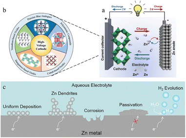 | ||
| Fig. 1 (a) Schematic illustration of the working principle of ZIBs. Adapted from ref. 11. Copyright 2020, Chem. Soc. Rev. (b) Representative cathode materials. Adapted from ref. 16. Copyright 2021, Wiley-VCH. (c) Schematic diagram of interactions with aqueous electrolyte on the zinc anode surface. | ||
This paper offers a comprehensive overview of the zinc anode of ZIBs. The Zn anode failure mechanism and principles are systematically discussed in terms of Zn dendrite growth, surface passivation and corrosion. Correspondingly, various optimization strategies are summarized to realize Zn anodes that can exhibit great performance. The methodologies for optimization involve the rational design of electrolytes, anode surface modification, and Zn host design. Finally, some potential future research directions are presented to build a better zinc anode model leading to good electrochemical performance of ZIBs.
2 Major challenges for the Zn anode
2.1 Zn dendrites
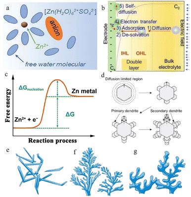 | ||
| Fig. 2 (a) Schematic illustration of the Zn2+-solvation structure. Adapted from ref. 43. Copyright 2020, Wiley-VCH. (b) Illustration of the zinc plating process. Adapted from ref. 40. Copyright 2022, Wiley-VCH. (c) Changes in free energy during Zn nucleation. Adapted from ref. 49. Copyright 2020, Wiley. (d) Schematic illustration of zinc dendrites. Adapted from ref. 47. Copyright 2015, Springer Nature. Morphology of dendrites: (e) needle-shaped dendrites. (f) Tree-shaped dendrites. (g) Moss-shaped dendrites. Adapted from ref. 46. Copyright 2019, Energy Chem. | ||
The Zn2+ ions are extracted from the cathode during the process of charging and are ultimately deposited on the anode side: firstly, the hydrated zinc ions bound to water molecules pass through the separator under the electric field and reach the anode side of the system. Secondly, the Zn2+ ions pass through the electric double layer and are dehydrated in the inner Helmholtz layer by a linear-diffusion controlled process.39 After the desolvation process, the dehydrated zinc ions are adsorbed on the zinc anode surface. Afterwards, these cations receive the electrons transferred through the external circuit, and the reduction process occurs. Once Zn2+ gains electrons from the current collector, an initial nucleation process occurs, and the newly formed reduced Zn will preferentially grow at the site of the initial nucleus (Fig. 2b). The reversibility of the plating reaction largely depends on the quality of the zinc nucleation and growth processes.40
Ideally, the electroreduction of Zn2+ presents a highly reversible electroplating and stripping process (eqn (1)) and does not generate undesirable by-products.
| Zn ↔ Zn2+ + 2e− | (1) |
In the nucleation process, zinc ions need to overcome the energy barrier of the nucleation over-potential,41 that is, the nucleation overpotential is one of the most important aspects of the zinc deposition process. The higher the nucleation overpotential, the more difficult the nucleation process will be (Fig. 2c). However, the uneven surface of the zinc foil piece, the different concentrations of zinc ions in different regions, and the presence of an abundance of water molecules near the anode region after the desolvation process make the environment of the anode side complicated and result in unsatisfactory reduction behaviour of the zinc ions.42
In practice, the reduction of zinc does not result in a uniform, smooth plane, which means that the newly formed reduced zinc metal does not always grow horizontally but displays a preferentially oriented growth process due to certain factors. This preferential growth orientation would create many inhomogeneous Zn nuclei and aggravate the uneven distribution of the ion flux due to the self-amplifying behaviour, resulting in unfavourable dendrites.43 As in the lithium-ion battery system, the dendrites grow continuously when the batteries are working.
Normally, at the beginning stage of the electroplating process, the new-born zinc metal displays a hexagonal close-packed morphology, where each atom can be bonded to the nearest six surrounding atoms through coordination bonds, and they display a strong preferential orientation to grow along the edge facets of the zinc hexagonal crystals.44 The primary zinc nuclei grow along the hexagonal edge facets and form primary dendrites, and branches reflecting the growth of new zinc nuclei along the primary dendrites subsequently appear, so that secondary dendrites occur (Fig. 2d). After this, more new-born dendrites begin to grow according to this rule, eventually forming an extensive loose mossy morphology or branch-like non-uniform dendrites (related to current density) (Fig. 2e–g).45–47
Uneven or loose zinc dendrite development will increase the electrode thickness, and the needle-shape dendrite protrusions may bring the danger of perforating the separator, leading to a sudden short circuit. Besides, the loose zinc deposit layer will cause low coulombic efficiency of the battery system due to the low bond strength.48 Dendrite growth is mainly affected by the following three issues: (1) the ion concentration and transmission rate, (2) electrical field strength and distribution, and (3) surface energy.36
During the diffusion process of zinc ions, the Zn2+ concentration is relatively stable in the main part of the electrolyte, but when they are close to the anode region, electroreduction begins to take place and zinc ions are consumed, while at the same time, water molecules that are exfoliated after desolvation accumulate near the negative electrode, resulting in a quick decrease in the zinc ion concentration near the interface and causing a concentration gradient (Fig. 3a and b).34,43 Even in a static electrochemical battery system, unavoidable and unpredictable natural convection exists, which can interfere with this process. This inevitably leads to differences in transport speed between cations as well, which also creates different concentration gradients around the anode region. Such a concentration gradient would result in a deposition process that is more likely to grow vertically rather than horizontally (Fig. 3c), ultimately promoting further dendrite growth.53
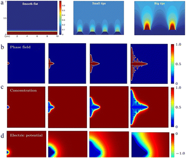 | ||
| Fig. 3 (a) Demonstration of tip effects in the form of electric field simulations. Adapted from ref. 57. Copyright 2019, Wiley. Dendrite growth of Li simulated by the phase-field model: (b) evolution of the order parameter, (c) concentration of Li+ and (d) electric potential. Adapted from ref. 59. Copyright 2015, Elsevier. | ||
Normally, the surface morphology of commonly used commercial zinc anodes is non-uniform on the micro/nanoscale, and the uneven surface leads to differences in the concentration of zinc ions in different surface regions. This concentration difference also leads to uneven deposition in the horizontal direction.46 To make matters worse, zinc ions tend to be deposited near an already existing nucleus with better lattice matching and affinity to reduce the surface energy, exacerbating the uneven growth of dendrites.12,54
It can be concluded that the even distribution of the Zn2+ concentration is critical for the deposition process, and proper control of the ion flux can effectively prevent the uneven deposition caused by localized rapid depletion of zinc ions and prevent the continuous growth of dendrites.40
As the electric field strength is stronger at a position with greater curvature where there is a higher surface charge density, the convex or the tip region of the anode surface has a stronger electric field, which means that the zinc ions reaching this region have higher energy to overcome the nucleation overpotential and thus are more easily reduced. This is “the tip effect” (Fig. 4a).56–58
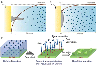 | ||
| Fig. 4 Schematic plots are shown for gradients in the ion concentration in (a) a strong concentration gradient and (b) a mild concentration gradient with corresponding metal morphologies near the electrode surface. Adapted from ref. 53. Copyright 2019, AAAS. (c) Illustration of the effect of concentration polarization on zinc deposition. Adapted from ref. 40. Copyright 2022, Wiley-VCH. | ||
In the ZIB system, a sharp initial zinc nucleus on the zinc metal foil anode will become a charge centre. A large number of charges accumulate in this region, and the strong electric field can provide greater force for zinc ion reduction.55,59,60 Once the “tip” emerges, this undesirable dendrite growth tendency will be further reinforced because of the stronger electrical field at tip sites. The charge accumulation in this area will then enhance the formation of zinc dendrites in the subsequent reactions (Fig. 4b–d).59
Recent studies have shown that higher current density is more likely to cause an uneven electrical field distribution, so a flat and smooth anode surface and relatively low current energy could efficiently make the electric field distribution uniform and guide the uniform deposition of zinc.57
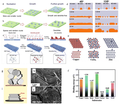 | ||
| Fig. 5 Schematic illustration of the Zn deposition process. (a) A uniform and dendrite-free zinc morphology is enabled by more and smaller nuclei. (b) Zn dendrites develop when there are few and random nuclei. Adapted from ref. 40. Copyright 2022, Wiley-VCH GmbH. (c) Effect of the 3D structure on zinc deposition. Adapted from ref. 64. Copyright 2022, Wiley-VCH GmbH. (d) Effect of the initial wetting angles on the following deposition process. Adapted from ref. 66. Copyright 2014, Elsevier Ltd. (e) The models of the affinity between different substrates and zinc. (f) Calculated binding energies between different substrates and zinc. Adapted from ref. 62. Copyright 2019, Wiley-VCH GmbH. (g) The epitaxial electrodeposition of Zn metal. (h) Morphology of zinc deposits on stainless steel. (i) Illustration of the uneven electrodeposition of Zn. (j) Morphology of zinc deposits on graphene-coated stainless steel. Adapted from ref. 68. Copyright 2019, AAAS. | ||
A higher specific surface area or abundant defects can supply numerous active deposition sites for zinc ions. The high specific surface area can also disperse the current, thereby reducing the specific current density. Therefore, a high electroactive surface area could inhibit dendrite formation.15,63 Hence, the use of substrate materials with a high specific surface area (such as porous structured or 3D structured anode substrates) often leads to relatively uniform zinc deposition.64 The high specific surface area can not only provide more electroplating sites (including a 3D/porous structure surface and the interior of the structure) for zinc ions, but also disperse the local current density and reduce the nucleation overpotential. Besides, the 3D/porous structure can also provide favourable ion transport channels by regulating the ion flux, so that the newly formed zinc nucleus is smaller and more abundant thus benefiting a uniform Zn deposition morphology (Fig. 5c).
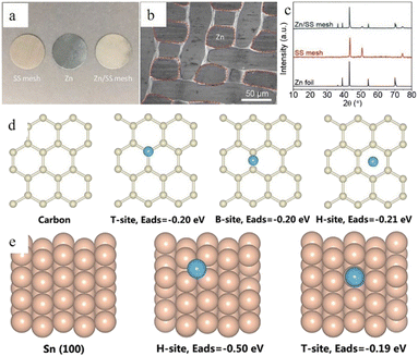
The affinity between Zn and the anode substrate is also important. A zinc–philic interface can not only reduce the nucleation overpotential by providing a more compatible interface and more electroactive sites, but also keep the deposited metallic zinc from peeling off through a strong electronic interaction.62,65 As shown in Fig. 5d, the nucleophilicity of the newly formed metal and the substrates directly affects the following deposition process.66 Density functional theory (DFT) calculations can be applied to illustrate the affinity between Zn and the anode substrate through the adsorption energy (EAds) (eqn (2)):
| EAds = ESys − ESub − EZn, | (2) |
Because zinc metal possesses a close-packed hexagonal structure, the packing plane spacing along the z-axis (5.21 Å) is longer than the in-plane bond length (2.63 Å). Besides, the highly exposed (001) plane has the lowest surface energy.44 This makes it easier for zinc to deposit and grow as hexagonal platelets along the ab-plane. According to the lattice-matching principle, newly formed zinc nuclei are more likely to grow along the direction with minimal lattice strain. As a result, the orientation of substrates can impact Zn growth, as initially, Zn typically develops epitaxially on the substrate. In an ideal electrodeposition process, zinc is more inclined to deposit parallel to the substrate surface as hexagonal platelets, which is divided into homogeneous and heterogeneous deposition according to the different epilayers and substrates,68 so the substrate surface undergoes repeated ideal electroplating/stripping processes and remains intact (Fig. 5i and j). However, the texture of the Zn anodes will be likely to change during cycling. When the plating/stripping rate of zinc is not suitable (the unevenness of the zinc anode surface, impurities, as well as differences in electric field strength and the presence of electrolyte concentration gradients can cause differences in the zinc deposition rate and the insufficient or over-sufficient electroplating/stripping caused by these differences could cause differences in nucleation size, orientation, and arrangement direction), the favourable (001) plane might be flipped or hidden, resulting in uneven zinc growth orientation (Fig. 5g and h).
It can be concluded from the above that an ideal substrate with a small lattice misfit with the (001) plane (normally no larger than 25%) and a low lattice index (indicating higher atomic packing density and surface stability) can induce epitaxial growth and uniform, compact electrodeposition behavior.68
2.2 Corrosion and passivation
In the zinc battery system, although the aqueous electrolyte guarantees the safety of the battery, it also has some problems. After the zinc ion desolvation process, a vast number of water molecules gather in the anode region, and the thermodynamic instability of zinc metal in an aqueous solution also increases the possibility of corrosion and passivation.69,70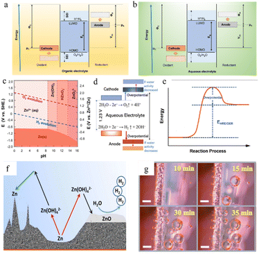 | ||
| Fig. 6 The open-circuit energy diagram of (a) organic electrolytes and (b) aqueous electrolytes. Eg is the ESW of electrolyte, μ is the redox potential of the electrode, and Φ is the work function of the electrode. (c) Pourbaix diagram of zinc in an aqueous environment, taking both the HER and OER into consideration. Adapted from ref. 77. Copyright 2016, Elsevier. (d) The ESW and water reactions in aqueous electrolyte. Adapted from ref. 40. Copyright 2022, Wiley-VCH. (e) Changes in free energy during the HER/OER. (f) The chemical routes and challenges of the Zn anode under alkaline conditions. Adapted from ref. 10. Copyright 2016, Wiley-VCH. (g) Hydrogen evolution on the electrode surface. Adapted from ref. 81. Copyright 2021, Wiley-VCH. | ||
Unfortunately, it is very difficult to build functional in situ SEI layers on zinc anodes spontaneously in aqueous electrolyte systems because the water decomposition products are volatile gases or soluble ions rather than precipitates, and due to the limited voltage window of water and relatively high potential of zinc deposition, the salt anion is hard to decompose in an aqueous electrolyte system (Fig. 6b). Even though some hydroxide precipitation layers might appear during cycling because of some local pH change, these naturally formed layers could not be a functional protective SEI layer due to their loose and unstable structure and the risk of peeling in the following cycling. Therefore, the corrosion and passivation mechanisms of water-based electrolyte systems are quite different from those of organic systems.52,73,74
The water molecules may undergo the hydrogen (H2) evolution reaction (HER) (eqn (3)) or the oxygen (O2) evolution reaction (OER) (eqn (4)) in aqueous electrolytes. The potential for gas production is influenced by the activity of the water molecules and the pH of the solution. From the Pourbaix diagram we can see that (Fig. 6c) the standard electrode potential of H+/H2 (0 V versus H+/H2) is larger than that of Zn2+/Zn (−0.76 V versus H+/H2), which means the thermodynamic favourability for the HER rather than Zn deposition in an aqueous system. However, the Zn deposition process still will happen ahead of the HER theoretically because zinc metal exhibits a high kinetic overpotential for the HER (Fig. 6e), relatively low H+ activity in mild acid electrolytes, and sluggish kinetics of hydrogen evolution.40
In the presented ZIBs, however, it is still challenging to fully eliminate side reactions, such as the HER and the OER. Once such side reactions occur, water molecules in the electrolyte will be rapidly consumed, resulting in poor coulombic efficiency and unstable cycling performance (Fig. 6f and g).
| 2H2O + 2e− → H2 + 2OH−. | (3) |
| H2O − 2e− → ½O2 + 2H+. | (4) |
The reactions involved during this process mainly include the following (eqn (5)–(7)):
| Zn → Zn2+ + 2e−. | (5) |
The corrosion reaction can be described as:
| Zn + 4OH− ↔ [Zn(OH)4]2− ↔ ZnO + H2O + 2OH−, | (6) |
| 2OH− + Zn ↔ Zn(OH)2 + 2e−, Zn(OH)2 → ZnO + H2O. | (7) |
The produced zinc oxide covers and passivates the electrode surface, creating a “dead” Zn region, which will cause an increase in internal resistance of the battery, the reduction of active sites on the electrode surface, and the enhancement of uneven electric field distribution, thus promoting dendrite growth. This process is also accompanied by a serious electrolyte consumption process and leads to poor coulombic efficiency and unstable cycling performance (Fig. 6f).10
In a strong acid electrolyte system (pH < 4.0), hydrogen evolution will dominate the entire reaction, and the hydrogen gas produced by the HER will cause battery swelling and electrode polarization (Fig. 6g).12,80,81 Moreover, the consumption of H+ will also lead to an increase in the system's content of OH− and a significant drop in the number of water molecules, leading to the appearance of undesirable by-products such as Zn(OH)2 and ZnSO4(OH)6·xH2O, and producing a dead zone caused by water shortage in the anode area.82 Severe hydrogen evolution and surface passivation occur at the same time, which results in a drastic deterioration of the battery performance. Therefore, the use of such strong acid electrolytes should be avoided in practical applications.
Therefore, a mildly acidic or neutral electrolyte system (ZnSO4, Zn(CF3SO3)2, zinc(II) bis(trifluoromethanesulfonyl)imide (Zn[TFSI]2), Zn(CH3COO)2, etc.) is more suitable for the ZIB system.83 Some inevitable corrosion side reactions still occur, however, due to the thermodynamic properties of zinc itself in an aqueous solution. Zinc sulphate hydroxide hydrate, zinc sulphate hydrate, zinc carbonate, or zinc chloride are the most common corrosion products. For example, the Zn4SO4(OH)6·xH2O non-conductive layer could be generated in a ZnSO4 electrolyte system.12 The corrosion behaviour of Zn in neutral or mildly acidic electrolytes will not only lead to the etching and corrosion of the anode surface, but the nonconductive, non-soluble by-products generated will also form a passivation layer on the anode surface.
When zinc is electro-oxidized to zinc ions in an aqueous solution, they rapidly solvate and combine with 10–12 water molecules to form a solvated structure. The standard electrochemical potential (E0) of Zn/Zn2+ is as follows:
| E0 = 0.059/2 × lg[Zn2+] − 0.763 (V). | (8) |
The electrochemical reaction taking place could be expressed as follows:
| Zn ↔ Zn2+ + 2e−. | (9) |
Another issue is that the metal Zn foil pieces currently used are not 100% pure but contain some other impurities introduced during the industrial manufacturing process. This results in the formation of microbatteries inside the batteries in aqueous electrolytes, in which impurities might act as the cathode, whereas metallic Zn could act as the anode, and the electrochemical reaction of the microbattery will accelerate the corrosion reaction in the system.
To sum up, the corrosion and passivation existing in zinc-ion batteries mainly include the following categories: (1) corrosion, (2) passivation and (3) the HER. The corrosion behaviour of metallic zinc may lead to the destruction of the zinc anode and exacerbate the roughness of the Zn surface, resulting in a rapid decline in battery performance. The adverse passivation layer formed by the undesirable by-products is insoluble, insulating, and harmful, since these inert products will coat the zinc anode surface, affecting the ionic diffusion and resulting in a rapid increase in battery impedance, which greatly hinders further electrochemical reactions and causes high polarization. Furthermore, these harmful by-products will induce the growth of dendrites, exacerbating problems inside the battery system.
The H2 generated by the HER will cause an increase in the battery's inner pressure, resulting in battery swelling and electrolyte leakage, putting the battery at risk of an explosion.81,84 To make matters worse, the corrosion, along with the hydrogen evolution reaction, will deplete active zinc metal and water molecules in the system. If the water in these water-depleted areas is not compensated in time, locally “dead” regions will occur.85
3 Optimization strategies
3.1 Electrolyte modification
As a carrier for zinc ion migration, the electrolyte is critical to the whole battery system, since the properties of the electrolyte can conspicuously affect the electrochemically stable potential windows and the efficiency of zinc deposition/stripping.86 Aqueous electrolytes commonly used in ZIBs have the advantages of high ionic conductivity, low cost, environmental friendliness, operational safety, and high efficiency compared to the lithium anode in non-aqueous electrolytes.15,34As mentioned before, an alkaline aqueous electrolyte is more prone to bringing about the generation of zinc dendrites and undesirable ZnO, although the severe HER and corrosion caused by a strong acid electrolyte are also harmful to the normal operation of the battery system, resulting in degradation of capacity and low coulombic efficiency. Therefore, a neutral or slightly acidic electrolyte has become a better choice for ZIBs. To date, various electrolytes, such as ZnSO4, Zn(CF3SO3)2, ZnCl2, Zn(TFSI)2, Zn(NO3)2, Zn(CH3COO)2, etc.,34 have been widely used in ZIBs, and most of the research on electrolyte modification has also been based on this electrolyte system. Zn(CF3SO3)2, ZnSO4 and Zn(TFSI)2 are the most often utilized zinc electrolyte salts due to their stable ionic species and high compatibility.
Some inevitable corrosion side reactions still occur, however, due to the thermodynamic properties of zinc itself in an aqueous solution.48 As the simplest and most direct method, electrolyte modification can often play a positive role in improving battery performance.87,88 Electrolyte regulation methods can be divided into three main categories: (1) “water in salt” electrolyte, (2) electrolyte additives, and (3) gel polymer or solid-state electrolytes.
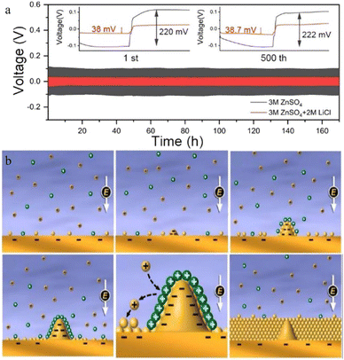
Guo et al.100 reported a new type of lithium chloride (LiCl) electrolyte additive in 3 M ZnSO4 which can possess a special synergistic manner to stabilize the Zn anode, and the zinc deposition overpotential of the 3 M ZnSO4/2 M LiCl electrolyte sample was reduced from 220 mV to 38 mV compared to that of the 2 M LiCl electrolyte sample (Fig. 8a). The Li+ cations can create an oxide-layer shielding effect by building a simple in situ grown Li2O/Li2CO3 protective layer, and the ion transmission efficiency can be effectively enhanced by the Cl− anions, thereby helping to decrease the polarization and repress the growth of Zn dendrites. Wan and colleagues101 added Na2SO4 into ZnSO4 to suppress the dissolution of the cathode material and inhibit Zn dendrite deposition. Since Zn2+ possesses a higher reduction potential than Na+, when the electrolyte system contains both sodium and zinc ions, the Zn dendrite growth will be suppressed because of the “electrostatic shield mechanism” (Fig. 8b).102 A similar “electrostatic shielding effect” will occur when other cations with lower reduction potentials are added.
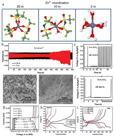 | ||
| Fig. 8 (a) Solvation structures of Zn2+ in 1 M Zn(TFSI)2 and various LiTFSI concentrations (5 M, 10 M, and 20 M). Adapted from ref. 52. Copyright 2018, Springer Nature. (b) The plating/stripping of zinc in ZnCl2. Coulombic efficiency (CE) of zinc plating/stripping in (c) 5 M and (f) 30 M ZnCl2 electrolytes. Scanning electron microscope (SEM) images of the zinc anode in (d) 5 M and (e) 30 M ZnCl2. (g) The electrochemical stability window of ZnCl2 at various concentrations. Adapted from ref. 91. Copyright 2018, The Royal Society of Chemistry. The corresponding voltage profiles of (h) 3 M and (i) 30 M ZnCl2. Adapted from ref. 92. Copyright 2021, Wiley-VCH. | ||
Some organic polymers are applied as additives to optimize the anode performance. The mode of action of organic electrolyte additives on anode electrode performance can be divided into two categories: (1) electrolyte structural modifiers for improving the ion transport efficiency, engaging the solvation structure (including adjustment of the solvation shell, manipulating the mobilities of Zn2+ cations and anions, and optimization of Zn ion coordination sites), or suppressing the side reactions; and (2) interface morphology modifiers for: adsorbing on the zinc surface to optimize the Zn plating/stripping process, building an in situ membrane to homogenize the ionic flux, or building a phase separation layer to separate the active water from the metallic zinc anode.
Surfactant type additives such as cetyltrimethylammonium bromide (CTAB),103,104 TBA2SO4,105 sodium dodecyl sulphate (SDS),106 SDBS,107 Triton X-100,108etc. with a hydrophilic and a hydrophobic part often possess good zincophilic ability (Fig. 9g and h), and they can adsorb on the zinc anode surface and form surfactant aggregates. These aggregates can cover the protuberances and tips and alter the surface energy.40 Besides, the hydrophobic side of these surfactants exhibits steric hindrance towards hydrated Zn2+ ions and reduces the dendritic growth.109 Bayaguud et al.103 reported low-cost, non-toxic TBA2SO4 as an additive in ZIBs. It was demonstrated that the protective TBA+ layers aggregate and adsorb near the protrusions, which could not only regulate the initial nuclear processes (Fig. 9a), but also drive the deposition of Zn2+ ions on adjacent flat regions (Fig. 9b). The unique zincophobic repulsion mechanism of TBA2SO4 effectively improved the electrochemical performance, resulting in a 98% CE in the first cycle at a current density of 10 mA cm−2. This protective layer could also prevent water from coming into contact with the electrode and inhibit the HER. In addition, some surfactant-type organic additives such as SDBS107 could facilitate epitaxial-growth-dominated exposed surfaces and suppress the vertical crystal growth direction of the (101) orientation (Fig. 9c–f).
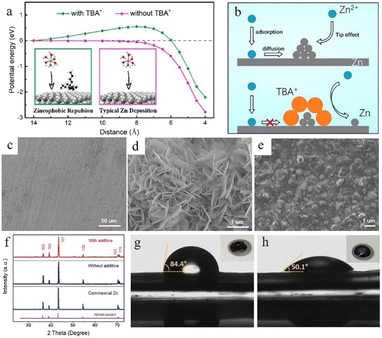 | ||
| Fig. 9 (a) The energy potential changes corresponding to different distances. (b) The transport and reduction of Zn2+ ions in 2 M ZnSO4 and in 0.05 mM tetrabutylammonium sulphate (TBA2SO4) in 2 M ZnSO4 electrolyte. Adapted from ref. 103. Copyright 2020, American Chemical Society. SEM images of (c) fresh zinc foil and the as deposited zinc anode (d) without additives and (e) with a sodium dodecylbenzene sulphonate (SDBS) additive. (f) XRD patterns of fresh zinc foil and the as deposited zinc anode with and without the SDBS additive. Measurements of contact angles on the LiFePO4 (LFP) electrode/electrolyte interface with (h) or without (g) SDBS additive. Adapted from ref. 107. Copyright 2019, Wiley-VCH. | ||
Polymers such as polyethylene oxide (PEO),110,111 polyethylene glycol (PEG),112 polyacrylamide (PAM),111etc. with different functional groups could generate distinctive interactions with Zn2+, the zinc anode surface, and water molecules. In the 1 M ZnSO4 electrolyte system, the long-chain PEO polymer was explored by Jin et al. as a multifunctional electrolyte additive.110 Nuclear magnetic resonance (NMR) characterization showed the interactions between PEO and Zn2+ ions (Fig. 10a), which can regulate the distribution and ion flux of Zn ions and adjust electrolyte viscosity. Long-chain polymer molecules can also slow down Zn2+ ion transport, resulting in a uniform Zn2+ distribution, which can promote a uniform zinc deposition. Furthermore, PEO is adsorbed on zinc anode surfaces and builds a protective layer, which can suppress the HER and enhance interface stability (Fig. 10b and c). The Zn anode with 1 M ZnSO4 + 0.5 wt% PEO displayed stable cycling for over 3000 h and a high CE of 99.5% at 1 mA cm−2.
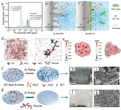 | ||
| Fig. 10 (a) Nuclear magnetic resonance (NMR) spectra of ether groups with different polyethylene oxide (PEO) contents. (b) The Zn plating process accompanied by dendritic growth and H2 evolution. (c) The effect of PEO polymer molecules on the anode region. Adapted from ref. 110. Copyright 2020, Wiley-VCH. (d) Schematic illustration of the ZnSO4–glucose system and Zn2+ solvation structure. (e) Electrostatic potential of Zn2+–6H2O (left) and glucose–Zn2+–5H2O (right) solvation structures. Schematic illustration of zinc deposition of (f) ZnSO4, (g) ZnSO4–glucose electrolyte, and (h–k) corresponding SEM images. Adapted from ref. 113. Copyright 2021, Wiley-VCH. | ||
Some organic chelating agents, including trisodium citrate,103 glucose,113 C8H19NO5 (BIS–TRIS),114,115 ethylenediaminetetraacetic acid (EDTA),116,117etc., are also used as electrolyte additives due to their strong chelating ability. These additive molecules can form strong bonds with Zn2+ ions, which could modulate the solvation sheath structure. Sun et al.113 used glucose to regulate the ZnSO4 electrolyte system, and the theoretical simulation confirmed that the glucose molecule in the electrolyte can rearrange the “Zn2+–xH2O–SO42−” solvation structure by substituting for one H2O molecule from the primary solvation shell (Fig. 10d), which could minimize the quantity of active water molecules and restrain side reactions (Fig. 10e). Besides, glucose molecules can be preferentially adsorbed on the surface of a Zn anode over water molecules, which aids in the desolvation process and suppresses the random growth of zinc dendrites (Fig. 10f and g). Their Zn//Ti battery with glucose–ZnSO4 electrolyte exhibited highly stable stripping/plating efficiency with a coulombic efficiency of 97.3% over 200 cycles, and their Zn//Zn symmetric battery with glucose–ZnSO4 electrolyte could cycle for 740 h at 2 mA cm−2 and 2000 h at a current density of 1 mA cm−2.
Using water-in-deep-eutectic-solvent (DES) electrolyte is another strategy.118–123 The water-in-DES electrolyte is obtained by mixing a Lewis base (such as urea,124,125 SN,121 acetamide,126,127etc.) and a Lewis acid (such as Zn(TFSI)2 and LiTFSI) in a eutectic molar ratio. The poor kinetic properties of such mixtures can be compensated for by adding a small amount of water. Zhao et al. reported a urea-based DES matrix,79 as shown in Fig. 11a–c. This electrolyte system features a strong interaction between organic additives and Zn2+, which can form a unique hydrogen-bonding network and confines all the water in its matrix (Fig. 11c). The solvation structure is rearranged into an organic coordinated solvation sheath. The activity of water is greatly weakened because of the limitation imposed by the hydrogen bond network, which effectively suppresses the occurrence of corrosion reactions. After a 30 h initial induction process, the “water-in-DES” electrolyte system can cycle stably for 2400 h at 0.1 mA cm−2.
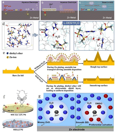 | ||
| Fig. 11 Interfacial reactions on the zinc anode: (a) hydrogen evolution process, (b) passivation and corrosion. (c) The role of water-in-DES electrolyte. Adapted from ref. 79. Copyright 2019, Elsevier Ltd. (d) Schematic illustration of the interaction of a lithium-based DES (L-DES)/H2O electrolyte system and the H2O molecule. (e) Illustration of morphology change in the zinc anode during the zinc stripping/electroplating cycle with and without the diethyl ether (Et2O) additive. Adapted from ref. 128. Copyright 2019, Elsevier. (f) Illustration of alcohol-based material additives. Adapted from ref. 131. Copyright 2022, Wiley-VCH. (g) Schematic illustration of solvated Zn2+ and surface evolution in H2O (left) and DMSO–H2O (right) systems. Adapted from ref. 132. Copyright 2022, American Chemical Society. | ||
Some organic liquids that are miscible with water (such as Et2O,128 methanol,129 glycerol,130 ethylene glycol,131etc.) can also help. Xu et al.128 reported a diethyl ether (Et2O) electrolyte additive that could be used to promote the electrochemical performance of the zinc anode. A very small amount of Et2O (2 vol%) can help to form a self-healing electrolyte by covering the protrusion tips and building a shielding layer (Fig. 11d and e). The battery with 2 vol% Et2O in a 3 M Zn(CF3SO3)2 electrolyte system showed good stability, and the polarization of the battery was reduced from 44 mV to 30 mV in the initial cycle with 30 mV maintained over the following 250 hours. Some other research studies on alcohol-based organic additives also proved that these additives can not only adsorb on the Zn surface and build a shielding layer, but also participate in the construction of a solvated structure (Fig. 11f).41 In addition, the hydrogen bonds between alcohol-based additives can also decrease water activity,131 while the adsorption of these additives on the zinc surface can improve their zincophilic capability and regulate the crystal growth orientation. Furthermore, some organic solvents (such as dimethyl sulfoxide (DMSO),132 triethyl phosphate (TEP),133 polyethylene oxide (PEO),134etc.) can achieve similar boosting effects at relatively low addition ratios compared to alcohol-based additives. Cao et al.132 proposed that DMSO which possesses a high Gutmann donor number can replace the water in the solvation structure and create a powerful DMSO–H2O interaction simultaneously to reduce the water activity. In addition, the solvated DMSO decomposition products can enrich the solid electrolyte interphase (SEI). The SEI prevents the penetration of water but allows the transportation of zinc ions, thus inhibiting the corrosion and passivation of the zinc surface and suppressing Zn dendrite growth (Fig. 11g). A symmetrical battery with ZnCl2–H2O–DMSO electrolyte could achieve long cycling stability, 1000 h at 0.5 mA cm−2 with ∼20.5 mV polarization overpotential. An average coulombic efficiency of 99.5% could also be obtained from a Zn//Ti battery with ZnCl2–H2O–DMSO electrolyte.
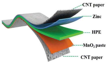 | ||
| Fig. 12 Diagram of the composition of an all-solid-state zinc-ion battery. Adapted from ref. 135. Copyright 2018, Royal Society of Chemistry. | ||
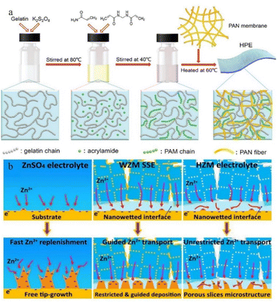 | ||
| Fig. 13 (a) Synthesis of HPE. Adapted from ref. 135. Copyright 2018, Royal Society of Chemistry. (b) Mechanisms of deposition behaviours of ZnSO4 electrolytes, water@ZnMOF-808-solid-state electrolyte (WZM), and hybrid ZnSO4@MOF-808 (HZM) electrolyte. Adapted from ref. 143. Copyright 2018 Elsevier Ltd. | ||
3.2 Anode surface modification
The anode surface is one of the most important areas in the whole zinc-ion battery. The electrolyte and electrode form a complex interfacial environment, which is not only the area where the electrochemical deposition/stripping of zinc metal occurs, but also the main area where dendrites grow and various unfavourable side effects (corrosion, passivation, and the HER) occur. The dynamic nucleation growth of zinc at this interface directly relates to the performance and lifetime of the battery.85,144–146 As mentioned above, some electrolyte additives are effective for optimizing the reaction interface by (1) adsorbing on the anode surface and modulating the ion flux to direct a mild interfacial concentration gradient; and (2) constructing an artificial SEI film to stabilize the interfacial environment and to regulate zinc deposition. In addition, electrode modification is also an important means to stabilize the interface environment. Protecting zinc metal anodes through the introduction of a protective layer is effective for easing the disordered growth of zinc. These functionalized protective layers can suppress the HER and surface corrosion and regulate the deposition behaviour by (1) controlling the ion flux, (2) confining the Zn nucleation sites, (3) building an interface with higher affinity and better lattice matching towards zinc, (4) physically separating zinc from the electrolyte, and (5) reducing the unevenness of the electrode surface created during the production process.In an aqueous electrolyte battery system, however, the decomposition products of water are gases, not sediments, and restricted by the limited voltage window of water and the higher reduction potential of zinc deposition, the salt anion is difficult to decompose. Even some local pH change during cycling could lead to the appearance of a hydroxide precipitation layer. This naturally formed unstable loose layer might be broken or peeled off from the zinc surface during the following cycles, so that it cannot be utilized as a protective layer. Therefore, some studies have pointed out that constructing a suitable artificial SEI layer that is stable, dense, and high zinc ion conductive will help to build homogeneous and fast Zn2+ transfer kinetics for dendrite free zinc plating and restrain side effects. For example, Hao et al.147 reported a polyvinyl butyral (PVB) film with high viscoelasticity as a functional artificial SEI layer to suppress the side effects on the zinc anode via the spin-coating method. The homogeneously deposited artificial layer with high ion conductivity could effectively block water from reaching the zinc anode, guide zinc ions for uniform stripping/plating, suppress dendrite growth, and enhance the CE. The Zn electrode with the PVB protective layer exhibits an extended cycling lifetime of 2200 h at 0.5 mA cm−2 in a Zn//Zn symmetric battery (Fig. 14a).
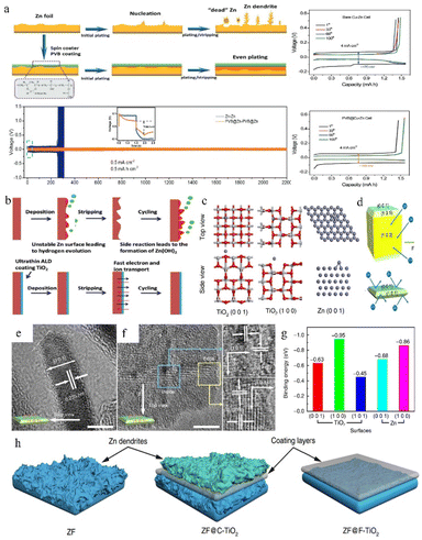 | ||
| Fig. 14 (a) Protective effect of the PVB layer on the Zn anode. Adapted from ref. 147. Copyright 2022, Wiley-VCH. (b) The positive effect of the TiO2 coating. Adapted from ref. 148. Copyright 2018, Wiley-VCH. (c) Computational simulations of Zn absorption on various crystal planes. (d) Interaction of different exposure surfaces between Zn and TiO2. (e and f) TEM images of F-TiO2. (g) Binding energies between zinc atoms with different facets. (h) The deposition behaviour of zinc on various coating layers. Adapted from ref. 65. Copyright 2018, Nature Communications. | ||
Zhao et al.148 used a TiO2 coating as the protection layer in ZIBs, because the TiO2 layer can work as a physical barrier separating the electrolyte and zinc metal and suppressing the undesirable corrosion reaction and HER (Fig. 14b). The 100TiO2@Zn symmetrical battery remained stable for over 150 h at 1 mA cm−2 with a lower overpotential (57.2 mV) than the pristine zinc anode (72.5 mV).
Zhang et al.65 investigated the affinity and degree of lattice matching of the TiO2 coating layers with different facets exposed to the Zn metal electrode. The models of zinc atoms attached to zinc and TiO2 surfaces respectively were simulated using DFT calculations (Fig. 14c). According to Fig. 14g, zinc displays a tendency to deposit on the TiO2 (1 0 0) plane rather than on the Zn surface because the TiO2 (1 0 0) facet and zinc atom possess higher binding energy than the zinc atom and zinc surface. This priority will cause zinc to grow upon the layer, which is unfavourable for zinc epitaxy deposition. Therefore, the F-TiO2 nanosheets with surface exposed (001) facets were synthesized by specific facet exposure control (Fig. 14d). Benefiting from the specific crystal-oriented structure of TiO2, the F-TiO2 nanosheets possessing high exposed (1 0 1) and (0 0 1) planes (Fig. 14e and f) could stabilize the interface and guide dendrites to grow in a uniform epitaxial manner rather than vertically, resulting in a long lifespan of their Zn anode (Fig. 14h).
Similarly, Kang et al.149 reported the effects of a porous nano-CaCO3 coating towards promoting the homogeneous deposition of zinc. The porous structure confined the nucleation in the Zn deposition process by influencing the nucleation sites and the electrolyte flux, resulting in homogeneous zinc deposition. The Zn symmetric battery with the nano-CaCO3 coating showed low nucleation polarization and maintained high plating/stripping reversibility for over 836 h at 0.25 mA cm−2 with a slight polarization increase of 25 mV. Xia et al.150 proposed a reduced graphene oxide (rGO) functionalized protective layer that could self-assemble on the zinc foil surface through uniform periodic stacking (Fig. 15c–e). The flexible matrix of the rGO layer could improve the structural stability of the anode, and the layer-by-layer structure is beneficial to uniform zinc plating (Fig. 15a and b). At the current densities of 0.2 mA cm−2, 0.4 mA cm−2, and 1 mA cm−2, the Zn/rGO|ZnSO4|Zn/rGO battery could exhibit a steady plating/stripping process with a flat voltage platform. The battery assembled with an active carbon material (AC)//Zn/rGO displayed better electrochemical properties than the bare Zn sample.
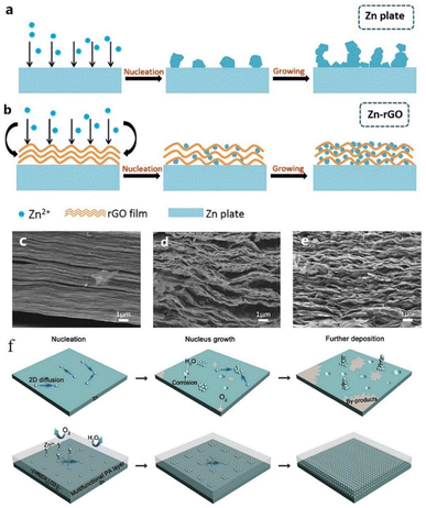 | ||
| Fig. 15 Zn deposition process on (a) the unprocessed Zn anode and (b) Zn–rGO anode. SEM images of rGO coating (c) before cycling and (d and e) after cycling. Adapted from ref. 150. Copyright 2019, Elsevier. (f) Zn plating process with PA coating. Adapted from ref. 151. Copyright 2019, The Royal Society of Chemistry. | ||
Zhao et al.151 reported a polyamide (PA) coating layer with a special hydrogen-bonding network, which possessed a powerful coordinating ability with Zn2+. The polyamide coating could act as a solid-state brightener to regulate the ion flux and control the two-dimensional diffusion of ions, resulting in a uniform nucleation process, thus separating water and the zinc anode to inhibit the occurrence of side reactions (Fig. 15f). The battery with the PA coating layer exhibited a long cycling life of over 8000 h in a galvanostatic cycling test at 0.5 mA cm−2, and the PA-Zn//Ti coin-type battery showed good cycling performance with an average coulombic efficiency of 95.12% over 300 cycles. He et al.152 reported a surface passivation strategy to form a continuous, conformal, strong passivation layer on the zinc surface by solution chemical treatment on the zinc surface with KMnO4 solution. The passivation layer exhibits excellent effects in improving the corrosion resistance of the electrode, smoothing the electrode surface, and promoting good plating/stripping performance. Zheng et al.68 reported a coating layer composed of graphene, which possesses a highly exposed (001) plane, causing low mismatch strain (7%) for Zn deposition. Therefore, Zn deposition with an (001) preferential orientation grows parallel to the substrate and exhibits a uniform epitaxial growth morphology.
3.3 Host design
Another strategy for regulating zinc anode deposition is host design, which may be classified into two categories: (1) 3D structures and (2) composite structures.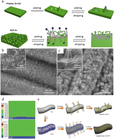 | ||
| Fig. 16 (a) Electro-plating/stripping process of pristine zinc and the 3D dual-channel porous Zn. Adapted from ref. 154. Copyright 2020, Elsevier. SEM images of (b) CNT and (c) Zn/CNT. (d) Electric field distribution models for the Zn-CC and Zn-CNT anodes after zinc nucleation. (e) Illustration of zinc plating on Zn-CC and Zn-CNT anodes. Adapted from ref. 155. Copyright 2019, Wiley-VCH. | ||
4 Summary and outlook
In summary, dendrites, corrosion, passivation, and the HER are the primary issues limiting the development of anodes for Zn-ion batteries. Dendrite growth is mainly affected by the ion concentration and transmission rate, the electrical field strength and distribution, the surface energy, including surface area, defects, affinity, and the degree of lattice matching with zinc metal, etc. Thus, the dendrite problem can be solved by adjusting the ion flux, increasing the nucleation sites, creating a uniform distribution of the electric field, and creating a surface space more suitable for uniform deposition to promote the homogeneous epitaxial deposition of zinc. Table 1 summarizes anode performance and test parameters.43,84,160| Anode | Electrolyte | Symmetrical battery performance | Asymmetric battery performance | Ref. | ||
|---|---|---|---|---|---|---|
| Current density (mA cm−2) | Lifespan | Current density (mA cm−2) | CE | |||
| Zn | 1 M Zn(TFSI)2 + 20 M LiTFSI | 0.2 | >170 h | 1 | >99.7% (>200 cycles) | 52 |
| Zn | 30 M ZnCl2 | 0.2 | >600 h | 1 | 95.4% (100 cycles) | 91 |
| Zn | 3 M ZnSO4/2 M LiCl | 0.2 | 170 h | — | — | 100 |
| 3D-Zn | 2 M ZnSO4 + TBA2SO4 | 5 | 456 h | 10 | 98% | 103 |
| Zn | 1 M ZnSO4 + 0.5 wt% PEO | 1 | 3000 h | 1 | 98.9% | 110 |
| Zn | Glucose in 1 M ZnSO4 | 1 | 2000 h | 1 | 97.3% (>200 cycles) | 113 |
| Zn | 30 mol% H2O + urea/LiTFSI/Zn(TFSI)2 | 0.1 | 2400 h | 0.5 | 96.2% (11th cycles) | 79 |
| Zn | 3 M Zn(CF3SO3)2 + 2 vol% Et2O | 0.2 | >500 h | — | — | 128 |
| Zn | ZnCl2–H2O–DMSO | 0.5 | 1000 h | 1 | 99.5% (400 cycles) | 132 |
| PVB@Zn | 1 M ZnSO4 | 0.5 | 2200 h | 4 | 99.4% (100 cycles) | 147 |
| Zn | Water@ZnMOF-808 (WZM) SSE | 0.1 | >360 h | — | — | 143 |
| F-TiO2 coated Zn | 1 M ZnSO4 | 1 | 460 h | — | — | 65 |
| CaCO3 coated Zn | ZnSO4 + MnSO4 | 0.25 | 836 h | — | — | 149 |
| rGO/Zn | 0.5 M ZnSO4 | 0.2 | 1000 cycles | — | — | 150 |
| Dual-channel 3D -Zn | 2 M Zn(CF3SO3)2 | 0.5 | 1400 h | 2 | 97.0% for over 50 cycles | 154 |
| PA-Zn | Zn(TfO)2 | 0.5 | 8000 h | 0.4 | 95.12% (300 cycles) | 151 |
| Cu–Zn/Zn | 3 M ZnSO4 | 1 | 1500 cycles | 5 | 91.8% (300 cycles) | 43 |
| MOF@Zn | 2 M ZnSO4 | 0.5 | >33![[thin space (1/6-em)]](https://www.rsc.org/images/entities/char_2009.gif) 000 h 000 h |
— | — | 84 |
| Indium-coated Zn | 1 M ZnSO4 | 1 | 1000 h | 0.5 | 99.7% (750 cycles) | 160 |
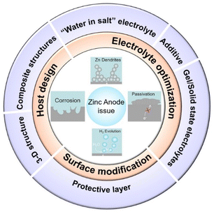
As for the corrosion, passivation, and HER, these unfavourable side effects are mainly caused by the thermodynamic properties of Zn itself and the inherent reactivity of water molecules. The modification approach is to diminish water activity, reduce the proportion of active water in the system or establish an artificial physical barrier to separate water and zinc. As shown in Fig. 18, the most commonly used negative electrode optimization methods are: (1) electrolyte optimization, (2) surface modification, and (3) anode host structure design. Since current anode optimization methods for aqueous zinc-ion batteries cannot meet the requirements of practical application and considering that the problems that can be solved by a single optimization strategy are very limited, multiple strategies can be used to enhance the overall zinc anode performance. Herein, we provide some perspectives and guidelines for future development of zinc ion batteries:
(1) Striking a balance between fully exploiting the advantages of ZIBs and suppressing dendrite growth and adverse effects: for example, the use of aqueous electrolytes with the advantages of safety, low price, and high efficiency, is one of the sources of competitiveness of zinc-ion batteries. Their inherent reactivity with zinc, however, is also the main reason for the problems of zinc anodes. Many optimization strategies currently employed are related to limiting the mobility of water or reducing the proportion of water while introducing other complex additives into the system, thus also introducing complexity into the system while increasing costs. Similarly, although some coating or structural modification strategies can effectively improve the battery performance, they also lead to an increase in cost and a decrease in energy density. Therefore, it is very important to seek simple, environmentally friendly, and efficient optimization methods.
(2) Research on the zinc stripping process and full cell performance: at present, great attention is still focused on the zinc deposition process on the anode side of zinc ion batteries, but it should be noted that the zinc stripping process is equally important for the reversibility of the battery, and therefore, it is necessary to devote sufficient research and attention to the zinc stripping process. In addition, the modification strategy for the battery anode should also take into account its effect on the cathode side, especially when implementing optimization strategies regarding electrolytes and separators. An excellent optimization strategy will be more valuable for the practical application of zinc ion battery systems if it can promote the electrochemical performance of both the cathode and the anode sides. Meanwhile, more advanced characterization techniques can be used to reveal the zinc deposition and stripping processes in more detail, such as in situ characterization, theoretical simulation calculations, etc.
(3) Further research on the anode electrode mechanism of ZIBs: at present, the research methods for the zinc anode reaction and failure mechanism have mainly drawn on the experience with some other types of rechargeable ion batteries. The unique aqueous electrolyte systems commonly used in zinc-ion batteries are quite different, however, from the organic electrolyte systems commonly used in lithium-ion or sodium-ion batteries. Also, there are some differences in the corrosion mechanism and dendrite growth process between aqueous electrolytes and organic electrolyte systems, so more research should be used to further analyse the interface between aqueous electrolytes and zinc metal. The study of the solvated sheath structure of zinc, as well as the formation, diffusion, and desolvation of the solvated structure requires more mature mechanism research and characterization methods.
(4) Optimization of the manufacturing technology: almost all current manufacturing of ZIBs is in the form of coin cells, so there is still some distance between actual application and laboratory research. Since the assembly of zinc-ion batteries can be directly completed in air and has good adaptability to the environment, researchers can make full use of this advantage to develop battery assembly forms that cannot be achieved with organic electrolyte battery systems.
(5) Development of other forms of water-based zinc batteries: due to the relatively narrow voltage window, the energy density of aqueous zinc ion batteries is still lower than that of organic battery systems. Therefore, the construction of new zinc-based battery systems (such as aqueous zinc–sulfur batteries, zinc–iodine batteries, etc.) using cathode materials that can show higher capacity may be a solution.
(6) Establishment of standardized experimental testing protocols: so far, although the aqueous-based zinc ion battery system is still a long distance from practical application, we believe that it is necessary to introduce certain specific test protocol standards when publishing related research work to get meaningful data which is representative of actual ZIB operating conditions. For example, excessive current density (over 10C) will cause capacitive behaviours to mask true zinc storage capacity and ultra-small capacity is meaningless because it cannot meet the needs of practical applications. A range of 0.5–2C is more recommended because it can meet the working current standards of most current energy storage devices.161 We recommend that the standard should include at least the following aspects: (1) the current rates in electrochemical testing, (2) loading mass of the active materials, (3) electrolyte parameters including the concentration, pH value and dosage, (4) environmental parameters during battery testing and so on. In addition, information on other components of the battery including the case, gaskets, separators, and the assembly process of the battery should also be listed in the article, and the repeatability of the test data should also be ensured.
(7) Expanding zinc-ion batteries to a wide range of applications: the safety of zinc-ion batteries has led to frequent reports on flexible ZIBs, which motivates the evolution of portable flexible batteries more suitable for flexible wearing. Simultaneously, the good biocompatibility of zinc-ion batteries also means that they could be used as biological power sources in medicine or other fields.
Author contributions
Y. Zhang and X. Zheng contributed equally to this work. The manuscript was written through the contributions of all the authors. All the authors have given approval to the final version of the manuscript.Conflicts of interest
There are no conflicts to declare.Acknowledgements
This work was supported by the Key R&D Program of Zhejiang Province (2021C04019), the National Natural Science Foundation of China (U20A20338), and the Australian Research Council (ARC) (DE170100928, DE220101113 and DP160102627), and the first author also would like to acknowledge the scholarship supported by the China Scholarship Council. We thank Dr Tania Silver for her critical reading of this manuscript.Notes and references
- D. Larcher and J.-M. Tarascon, Nat. Chem., 2015, 7, 19–29 CrossRef CAS.
- D. A. Notter, M. Gauch, R. Widmer, P. Wäger, A. Stamp, R. Zah and H.-J. Althaus, Environ. Sci. Technol., 2010, 44, 6550–6556 CrossRef CAS.
- M. A. Hannan, M. M. Hoque, A. Mohamed and A. Ayob, Renewable Sustainable Energy Rev., 2017, 69, 771–789 CrossRef.
- E. Telaretti and L. Dusonchet, Renewable Sustainable Energy Rev., 2017, 75, 380–392 CrossRef.
- Y. Tong, J. Liang, H. K. Liu and S. X. Dou, Energy Storage Mater., 2019, 20, 176–187 CrossRef.
- J. Winsberg, T. Janoschka, S. Morgenstern, T. Hagemann, S. Muench, G. Hauffman, J.-F. Gohy, M. D. Hager and U. S. Schubert, Adv. Mater., 2016, 28, 2238–2243 CrossRef CAS PubMed.
- C. Xu, B. Li, H. Du and F. Kang, Angew. Chem., Int. Ed., 2012, 124, 957–959 CrossRef.
- P. Ruan, S. Liang, B. Lu, H. J. Fan and J. Zhou, Angew. Chem., Int. Ed., 2022, 61, e202200598 CrossRef CAS PubMed.
- J. Ming, J. Guo, C. Xia, W. Wang and H. N. Alshareef, Mater. Sci. Eng., R, 2019, 135, 58–84 CrossRef.
- J. Fu, Z. P. Cano, M. G. Park, A. Yu, M. Fowler and Z. Chen, Adv. Mater., 2017, 29, 1604685 CrossRef PubMed.
- N. Zhang, X. Chen, M. Yu, Z. Niu, F. Cheng and J. Chen, Chem. Soc. Rev., 2020, 49, 4203–4219 RSC.
- H. He, H. Qin, J. Wu, X. Chen, R. Huang, F. Shen, Z. Wu, G. Chen, S. Yin and J. Liu, Energy Storage Mater., 2021, 43, 317–336 CrossRef.
- X. Zeng, J. Hao, Z. Wang, J. Mao and Z. Guo, Energy Storage Mater., 2019, 20, 410–437 CrossRef.
- D. Chen, M. Lu, D. Cai, H. Yang and W. Han, J. Energy Chem., 2021, 54, 712–726 CrossRef CAS.
- G. Fang, J. Zhou, A. Pan and S. Liang, ACS Energy Lett., 2018, 3, 2480–2501 CrossRef CAS.
- J. Yan, E. H. Ang, Y. Yang, Y. Zhang, M. Ye, W. Du and C. C. Li, Adv. Funct. Mater., 2021, 31, 2010213 CrossRef CAS.
- X. Li, Z. Chen, Y. Yang, S. Liang, B. Lu and J. Zhou, Inorg. Chem. Front., 2022, 9, 3986–3998 RSC.
- S.-D. Han, S. Kim, D. Li, V. Petkov, H. D. Yoo, P. J. Phillips, H. Wang, J. J. Kim, K. L. More, B. Key, R. F. Klie, J. Cabana, V. R. Stamenkovic, T. T. Fister, N. M. Markovic, A. K. Burrell, S. Tepavcevic and J. T. Vaughey, Chem. Mater., 2017, 29, 4874–4884 CrossRef CAS.
- M. H. Alfaruqi, V. Mathew, J. Gim, S. Kim, J. Song, J. P. Baboo, S. H. Choi and J. Kim, Chem. Mater., 2015, 27, 3609–3620 CrossRef CAS.
- P. Ruan, X. Xu, D. Zheng, X. Chen, X. Yin, S. Liang, X. Wu, W. Shi, X. Cao and J. Zhou, ChemSusChem, 2022, 15, e202201118 CrossRef CAS PubMed.
- H. Luo, B. Wang, C. Wang, F. Wu, F. Jin, B. Cong, Y. Ning, Y. Zhou, D. Wang, H. Liu and S. Dou, Energy Storage Mater., 2020, 33, 390–398 CrossRef.
- H. Chen, L. Chen, J. Meng, Z. Yang, J. Wu, Y. Rong, L. Deng and Y. Shi, J. Power Sources, 2020, 474, 228569 CrossRef CAS.
- X. Liang, J. Hao, B. Tan, X. Lu and W. Li, J. Power Sources, 2020, 472, 228507 CrossRef CAS.
- G. Ni, X. Xu, Z. Hao, W. Wang, C. Li, Y. Yang, C. Zhou, L. Qin, W. Chen, X. Yao and J. Cai, ACS Appl. Energy Mater., 2021, 4, 602–610 CrossRef CAS.
- T. Gupta, A. Kim, S. Phadke, S. Biswas, T. Luong, B. J. Hertzberg, M. Chamoun, K. Evans-Lutterodt and D. A. Steingart, J. Power Sources, 2016, 305, 22–29 CrossRef CAS.
- Z. Jia, B. Wang and Y. Wang, Mater. Chem. Phys., 2015, 149–150, 601–606 CrossRef CAS.
- Q. Li, Q. Zhang, Z. Zhou, W. Gong, C. Liu, Y. Feng, G. Hong and Y. Yao, Nano Res., 2021, 14, 91–99 CrossRef CAS.
- Y. Lu, J. Wang, S. Zeng, L. Zhou, W. Xu, D. Zheng, J. Liu, Y. Zeng and X. Lu, J. Mater. Chem. A, 2019, 7, 21678–21683 RSC.
- G. Li, Z. Yang, Y. Jiang, C. Jin, W. Huang, X. Ding and Y. Huang, Nano Energy, 2016, 25, 211–217 CrossRef CAS.
- W. Li, K. Wang, S. Cheng and K. Jiang, Energy Storage Mater., 2018, 15, 14–21 CrossRef.
- Q. Zhao, W. Huang, Z. Luo, L. Liu, Y. Lu, Y. Li, L. Li, J. Hu, H. Ma and J. Chen, Sci. Adv., 2018, 4, eaao1761 CrossRef PubMed.
- D. Kundu, P. Oberholzer, C. Glaros, A. Bouzid, E. Tervoort, A. Pasquarello and M. Niederberger, Chem. Mater., 2018, 30, 3874–3881 CrossRef CAS.
- R. Qin, Y. Wang, M. Zhang, Y. Wang, S. Ding, A. Song, H. Yi, L. Yang, Y. Song, Y. Cui, J. Liu, Z. Wang, S. Li, Q. Zhao and F. Pan, Nano Energy, 2021, 80, 105478 CrossRef CAS.
- K. E. K. Sun, T. K. A. Hoang, T. N. L. Doan, Y. Yu, X. Zhu, Y. Tian and P. Chen, ACS Appl. Mater. Interfaces, 2017, 9, 9681–9687 CrossRef CAS PubMed.
- F. Y. Cheng, J. Chen, X. L. Gou and P. W. Shen, Adv. Mater., 2005, 17, 2753–2756 CrossRef CAS.
- C. Xie, Y. Li, Q. Wang, D. Sun, Y. Tang and H. Wang, Carbon Energy, 2020, 2, 540–560 CrossRef CAS.
- D. Liu, Y. Tong, X. Yan, J. Liang and S. X. Dou, Batteries Supercaps, 2019, 2, 743–765 CrossRef.
- T. K. A. Hoang, T. N. L. Doan, K. E. K. Sun and P. Chen, RSC Adv., 2015, 5, 41677–41691 RSC.
- J. W. Diggle, A. R. Despic and J. O. Bockris, J. Electrochem. Soc., 1969, 116, 1503 CrossRef CAS.
- D. Wang, Q. Li, Y. Zhao, H. Hong, H. Li, Z. Huang, G. Liang, Q. Yang and C. Zhi, Adv. Energy Mater., 2022, 12, 2102707 CrossRef CAS.
- X. Han, S. Zhou, Y. Tan, X. Wu, F. Gao, Z. Liao, R. Huang, Y. Feng, X. Lu, S. Xie and L. Zheng, Angew. Chem., Int. Ed., 2008, 47, 5340–5343 CrossRef CAS PubMed.
- C. Li, X. Xie, S. Liang and J. Zhou, Energy Environ. Mater., 2020, 3, 146–159 CrossRef CAS.
- H. Yang, Z. Chang, Y. Qiao, H. Deng, X. Mu, P. He and H. Zhou, Angew. Chem., Int. Ed., 2020, 59, 9377–9381 CrossRef CAS PubMed.
- X. Jia, C. Liu, Z. G. Neale, J. Yang and G. Cao, Chem. Rev., 2020, 120, 7795–7866 CrossRef CAS PubMed.
- P. He, Q. Chen, M. Yan, X. Xu, L. Zhou, L. Mai and C.-W. Nan, EnergyChem, 2019, 1, 100022 CrossRef.
- H. Liu, X.-B. Cheng, Z. Jin, R. Zhang, G. Wang, L.-Q. Chen, Q.-B. Liu, J.-Q. Huang and Q. Zhang, EnergyChem, 2019, 1, 100003 CrossRef.
- M. Chamoun, B. J. Hertzberg, T. Gupta, D. Davies, S. Bhadra, B. Van Tassell, C. Erdonmez and D. A. Steingart, NPG Asia Mater., 2015, 7, e178 CrossRef.
- A. R. Mainar, E. Iruin, L. C. Colmenares, A. Kvasha, I. de Meatza, M. Bengoechea, O. Leonet, I. Boyano, Z. Zhang and J. A. Blazquez, J. Energy Stor., 2018, 15, 304–328 CrossRef.
- X. Xu, Y. Chen, D. Zheng, P. Ruan, Y. Cai, X. Dai, X. Niu, C. Pei, W. Shi, W. Liu, F. Wu, Z. Pan, H. Li and X. Cao, Small, 2021, 17, 2101901 CrossRef CAS PubMed.
- H. Liu, Y. Zhang, C. Wang, J. N. Glazer, Z. Shan and N. Liu, ACS Appl. Mater. Interfaces, 2021, 13, 32930–32936 CrossRef CAS PubMed.
- P. Liang, J. Yi, X. Liu, K. Wu, Z. Wang, J. Cui, Y. Liu, Y. Wang, Y. Xia and J. Zhang, Adv. Funct. Mater., 2020, 30, 1908528 CrossRef CAS.
- F. Wang, O. Borodin, T. Gao, X. Fan, W. Sun, F. Han, A. Faraone, J. A. Dura, K. Xu and C. Wang, Nat. Mater., 2018, 17, 543–549 CrossRef CAS PubMed.
- J. Xiao, Science, 2019, 366, 426–427 CrossRef CAS PubMed.
- X. Li, Q. Li, Y. Hou, Q. Yang, Z. Chen, Z. Huang, G. Liang, Y. Zhao, L. Ma, M. Li, Q. Huang and C. Zhi, ACS Nano, 2021, 15, 14631–14642 CrossRef CAS PubMed.
- Q. Yang, Q. Li, Z. Liu, D. Wang, Y. Guo, X. Li, Y. Tang, H. Li, B. Dong and C. Zhi, Adv. Mater., 2020, 32, 2001854 CrossRef CAS PubMed.
- B. J. L. Barton and J. O. Bockeris, Proc. R. Soc. London, Ser. A, 1962, 268, 485–505 Search PubMed.
- Q. Yang, G. Liang, Y. Guo, Z. Liu, B. Yan, D. Wang, Z. Huang, X. Li, J. Fan and C. Zhi, Adv. Mater., 2019, 31, 1903778 CrossRef CAS PubMed.
- W. Zhang, H. L. Zhuang, L. Fan, L. Gao and Y. Lu, Sci. Adv., 2018, 4, eaar4410 CrossRef PubMed.
- L. Chen, H. W. Zhang, L. Y. Liang, Z. Liu, Y. Qi, P. Lu, J. Chen and L.-Q. Chen, J. Power Sources, 2015, 300, 376–385 CrossRef CAS.
- C. Liu, Q. Lu, A. Omar and D. Mikhailova, Nanomaterials, 2021, 11, 764 CrossRef CAS PubMed.
- Y. Yin, S. Wang, Q. Zhang, Y. Song, N. Chang, Y. Pan, H. Zhang and X. Li, Adv. Mater., 2020, 32, 1906803 CrossRef CAS PubMed.
- Q. Zhang, J. Luan, L. Fu, S. Wu, Y. Tang, X. Ji and H. Wang, Angew. Chem., 2019, 131, 15988–15994 CrossRef.
- M. Du, Z. Miao, H. Li, Y. Sang, H. Liu and S. Wang, J. Mater. Chem. A, 2021, 9, 19245–19281 RSC.
- N. Guo, W. Huo, X. Dong, Z. Sun, Y. Lu, X. Wu, L. Dai, L. Wang, H. Lin, H. Liu, H. Liang, Z. He and Q. Zhang, Small Methods, 2022, 6, 2200597 CrossRef CAS PubMed.
- Q. Zhang, J. Luan, X. Huang, Q. Wang, D. Sun, Y. Tang, X. Ji and H. Wang, Nat. Commun., 2020, 11, 3961 CrossRef CAS PubMed.
- D. R. Ely, A. Jana and R. E. García, J. Power Sources, 2014, 272, 581–594 CrossRef CAS.
- L. Shan, Y. Wang, S. Liang, B. Tang, Y. Yang, Z. Wang, B. Lu and J. Zhou, InfoMat, 2021, 3, 1028–1036 CrossRef CAS.
- J. Zheng, Q. Zhao, T. Tang, J. Yin, C. D. Quilty, G. D. Renderos, X. Liu, Y. Deng, L. Wang, D. C. Bock, C. Jaye, D. Zhang, E. S. Takeuchi, K. J. Takeuchi, A. C. Marschilok and L. A. Archer, Science, 2019, 366, 645–648 CrossRef CAS PubMed.
- R. Zhao, Y. Yang, G. Liu, R. Zhu, J. Huang, Z. Chen, Z. Gao, X. Chen and L. Qie, Adv. Funct. Mater., 2021, 31, 2001867 CrossRef CAS.
- W. He, S. Wang, Y. Shao, Z. Kong, H. Tu, Y. Wu and X. Hao, Adv. Energy Mater., 2021, 11, 2003268 CrossRef CAS.
- A. Wang, S. Kadam, H. Li, S. Shi and Y. Qi, npj Comput. Mater., 2018, 4, 15 CrossRef.
- T. Zhang, Y. Tang, S. Guo, X. Cao, A. Pan, G. Fang, J. Zhou and S. Liang, Energy Environ. Sci., 2020, 13, 4625–4665 RSC.
- X. Zeng, J. Mao, J. Hao, J. Liu, S. Liu, Z. Wang, Y. Wang, S. Zhang, T. Zheng, J. Liu, P. Rao and Z. Guo, Adv. Mater., 2021, 33, 2007416 CrossRef CAS PubMed.
- X. Li, J. Zeng, H. Yao, D. Yuan and L. Zhang, ChemNanoMat, 2021, 7, 1162–1176 CrossRef CAS.
- B. Hwang, E.-S. Oh and K. Kim, Electrochim. Acta, 2016, 216, 484–489 CrossRef CAS.
- V. Ravindran and V. S. Muralidharan, Anti-Corros. Methods Mater., 1995, 42, 10–12 CrossRef CAS.
- A. Krężel and W. Maret, Arch. Biochem. Biophys., 2016, 611, 3–19 CrossRef PubMed.
- X. Lv, W. Wei, H. Wang, B. Huang and Y. Dai, Appl. Catal., B, 2020, 264, 118521 CrossRef CAS.
- J. Zhao, J. Zhang, W. Yang, B. Chen, Z. Zhao, H. Qiu, S. Dong, X. Zhou, G. Cui and L. Chen, Nano Energy, 2019, 57, 625–634 CrossRef CAS.
- K. Wippermann, J. W. Schultze, R. Kessel and J. Penninger, Corros. Sci., 1991, 32, 205–230 CrossRef CAS.
- L. Ma, Q. Li, Y. Ying, F. Ma, S. Chen, Y. Li, H. Huang and C. Zhi, Adv. Mater., 2021, 33, 2007406 CrossRef CAS PubMed.
- N. Wang, H. Wan, J. Duan, X. Wang, L. Tao, J. Zhang and H. Wang, Mater. Today Adv., 2021, 11, 100149 CrossRef CAS.
- L. M. Baugh, Electrochim. Acta, 1979, 24, 657–667 CrossRef CAS.
- Z. Cai, Y. Ou, J. Wang, R. Xiao, L. Fu, Z. Yuan, R. Zhan and Y. Sun, Energy Storage Mater., 2020, 27, 205–211 CrossRef.
- Q. Zhang, J. Luan, Y. Tang, X. Ji and H. Wang, Angew. Chem., Int. Ed., 2020, 59, 13180–13191 CrossRef CAS PubMed.
- J. Mao, J. Iocozzia, J. Huang, K. Meng, Y. Lai and Z. Lin, Energy Environ. Sci., 2018, 11, 772–799 RSC.
- S. Guo, L. Qin, T. Zhang, M. Zhou, J. Zhou, G. Fang and S. Liang, Energy Storage Mater., 2021, 34, 545–562 CrossRef.
- C. Li, L. Wang, J. Zhang, D. Zhang, J. Du, Y. Yao and G. Hong, Energy Storage Mater., 2022, 44, 104–135 CrossRef.
- L. Suo, O. Borodin, T. Gao, M. Olguin, J. Ho, X. Fan, C. Luo, C. Wang and K. Xu, Science, 2015, 350, 938–943 CrossRef CAS PubMed.
- Y. Wang, Z. Wang, F. Yang, S. Liu, S. Zhang, J. Mao and Z. Guo, Small, 2022, 2107033 CrossRef CAS PubMed.
- C. Zhang, J. Holoubek, X. Wu, A. Daniyar, L. Zhu, C. Chen, D. P. Leonard, I. A. Rodríguez-Pérez, J.-X. Jiang, C. Fang and X. Ji, Chem. Commun., 2018, 54, 14097–14099 RSC.
- L. Wang, S. Yan, C. D. Quilty, J. Kuang, M. R. Dunkin, S. N. Ehrlich, L. Ma, K. J. Takeuchi, E. S. Takeuchi and A. C. Marschilok, Adv. Mater. Interfaces, 2021, 8, 2002080 CrossRef CAS.
- G. Chang, S. Liu, Y. Fu, X. Hao, W. Jin, X. Ji and J. Hu, Adv. Mater. Interfaces, 2019, 6, 1901358 CrossRef CAS.
- J. Hao, X. Li, X. Zeng, D. Li, J. Mao and Z. Guo, Energy Environ. Sci., 2020, 13, 3917–3949 RSC.
- Z. Yuan, Y. Yin, C. Xie, H. Zhang, Y. Yao and X. Li, Adv. Mater., 2019, 31, 1902025 CrossRef CAS PubMed.
- N. Sorour, W. Zhang, E. Ghali and G. Houlachi, Hydrometallurgy, 2017, 171, 320–332 CrossRef CAS.
- S. Clark, A. R. Mainar, E. Iruin, L. C. Colmenares, J. A. Blázquez, J. R. Tolchard, Z. Jusys and B. Horstmann, Adv. Energy Mate., 2020, 10, 1903470 CrossRef CAS.
- J. Cao, D. Zhang, Y. Yue, R. Chanajaree, S. Wang, J. Han, X. Zhang, J. Qin and Y. Huang, Nano Energy, 2022, 93, 106839 CrossRef CAS.
- Y. Wang, T. Guo, J. Yin, Z. Tian, Y. Ma, Z. Liu, Y. Zhu and H. N. Alshareef, Adv. Mater., 2022, 34, 2106937 CrossRef CAS PubMed.
- X. Guo, Z. Zhang, J. Li, N. Luo, G.-L. Chai, T. S. Miller, F. Lai, P. Shearing, D. J. L. Brett, D. Han, Z. Weng, G. He and I. P. Parkin, ACS Energy Lett., 2021, 6, 395–403 CrossRef CAS.
- F. Wan, L. Zhang, X. Dai, X. Wang, Z. Niu and J. Chen, Nat. Commun., 2018, 9, 1656 CrossRef PubMed.
- F. Ding, W. Xu, G. L. Graff, J. Zhang, M. L. Sushko, X. Chen, Y. Shao, M. H. Engelhard, Z. Nie, J. Xiao, X. Liu, P. V. Sushko, J. Liu and J.-G. Zhang, J. Am. Chem. Soc., 2013, 135, 4450–4456 CrossRef CAS PubMed.
- A. Bayaguud, X. Luo, Y. Fu and C. Zhu, ACS Energy Lett., 2020, 5, 3012–3020 CrossRef CAS.
- J. Hao, J. Long, B. Li, X. Li, S. Zhang, F. Yang, X. Zeng, Z. Yang, W. K. Pang and Z. Guo, Adv. Funct. Mater., 2019, 29, 1903605 CrossRef.
- J. Zhu, Y. Zhou and C. Gao, J. Power Sources, 1998, 72, 231–235 CrossRef CAS.
- R. K. Ghavami and Z. Rafiei, J. Power Sources, 2006, 162, 893–899 CrossRef CAS.
- Z. Hou, X. Zhang, X. Li, Y. Zhu, J. Liang and Y. Qian, J. Mater. Chem. A, 2017, 5, 730–738 RSC.
- J. Kan, H. Xue and S. Mu, J. Power Sources, 1998, 74, 113–116 CrossRef CAS.
- A. R. Mainar, L. C. Colmenares, J. A. Blázquez and I. Urdampilleta, Int. J. Energy Res., 2018, 42, 903–918 CrossRef.
- Y. Jin, K. S. Han, Y. Shao, M. L. Sushko, J. Xiao, H. Pan and J. Liu, Adv. Funct. Mater., 2020, 30, 2003932 CrossRef CAS.
- M. Yan, N. Dong, X. Zhao, Y. Sun and H. Pan, ACS Energy Lett, 2021, 6, 3236–3243 CrossRef CAS.
- M. Li, S. Luo, Y. Qian, W. Zhang, L. Jiang and J. Shen, J. Electrochem. Soc., 2007, 154, D567 CrossRef CAS.
- P. Sun, L. Ma, W. Zhou, M. Qiu, Z. Wang, D. Chao and W. Mai, Angew. Chem., Int. Ed., 2021, 133, 18395–18403 CrossRef.
- M. Luo, C. Wang, H. Lu, Y. Lu, B. B. Xu, W. Sun, H. Pan, M. Yan and Y. Jiang, Energy Storage Mater., 2021, 41, 515–521 CrossRef.
- N. Wang, S. Zhai, Y. Ma, X. Tan, K. Jiang, W. Zhong, W. Zhang, N. Chen, W. Chen, S. Li, G. Han and Z. Li, Energy Storage Mater., 2021, 43, 585–594 CrossRef.
- S. Zhang, J. Hao, D. Luo, P. Zhang, B. Zhang, K. Davey, Z. Lin and S. Qiao, Adv. Energy Mater., 2021, 11, 2102010 CrossRef CAS.
- J. Cao, D. Zhang, R. Chanajaree, Y. Yue, Z. Zeng, X. Zhang and J. Qin, Adv. Powder Mater., 2022, 1, 100007 CrossRef.
- O. S. Hammond, D. T. Bowron and K. J. Edler, Angew. Chem., Int. Ed., 2017, 56, 9782–9785 CrossRef CAS PubMed.
- Q. Zhang, K. De Oliveira Vigier, S. Royer and F. Jérôme, Chem. Soc. Rev., 2012, 41, 7108 RSC.
- H. Zhang, M. L. Ferrer, M. J. Roldán-Ruiz, R. J. Jiménez-Riobóo, M. C. Gutiérrez and F. del Monte, J. Phys. Chem. B, 2020, 124, 4002–4009 CrossRef CAS PubMed.
- C. Han, W. Li, H. K. Liu, S. Dou and J. Wang, Nano Energy, 2020, 74, 104880 CrossRef CAS.
- C. Liu, X. Xie, B. Lu, J. Zhou and S. Liang, ACS Energy Lett., 2021, 6, 1015–1033 CrossRef CAS.
- N. López-Salas, J. M. Vicent-Luna, S. Imberti, E. Posada, M. J. Roldán, J. A. Anta, S. R. G. Balestra, R. M. Madero Castro, S. Calero, R. J. Jiménez-Riobóo, M. C. Gutiérrez, M. L. Ferrer and F. del Monte, ACS Sustainable Chem. Eng., 2019, 7, 17565–17573 CrossRef.
- M. Shehata, A. Unlu, U. Sezerman and E. Timucin, J. Phys. Chem. B, 2020, 124, 8801–8810 CrossRef CAS PubMed.
- R. Li, Q. Dong, J. Xia, C. Luo, L. Sheng, F. Cheng and J. Liang, Surf. Coat. Technol., 2019, 366, 138–145 CrossRef CAS.
- G. Carrasco-Huertas, R. J. Jiménez-Riobóo, M. C. Gutiérrez, M. L. Ferrer and F. del Monte, Chem. Commun., 2020, 56, 3592–3604 RSC.
- F. Ilyas, M. Ishaq, M. Jabeen, M. Saeed, A. Ihsan and M. Ahmed, J. Mol. Liq., 2021, 343, 117606 CrossRef CAS.
- W. Xu, K. Zhao, W. Huo, Y. Wang, G. Yao, X. Gu, H. Cheng, L. Mai, C. Hu and X. Wang, Nano Energy, 2019, 62, 275–281 CrossRef CAS.
- J. Hao, L. Yuan, C. Ye, D. Chao, K. Davey, Z. Guo and S. Qiao, Angew. Chem., Int. Ed., 2021, 60, 7366–7375 CrossRef CAS PubMed.
- Y. Zhang, M. Zhu, K. Wu, F. Yu, G. Wang, G. Xu, M. Wu, H.-K. Liu, S.-X. Dou and C. Wu, J. Mater. Chem. A, 2021, 9, 4253–4261 RSC.
- Y. Shang, P. Kumar, T. Musso, U. Mittal, Q. Du, X. Liang and D. Kundu, Adv. Funct. Mater., 2022, 2200606 CrossRef CAS.
- L. Cao, D. Li, E. Hu, J. Xu, T. Deng, L. Ma, Y. Wang, X.-Q. Yang and C. Wang, J. Am. Chem. Soc., 2020, 142, 21404–21409 CrossRef CAS PubMed.
- A. Naveed, H. Yang, J. Yang, Y. Nuli and J. Wang, Angew. Chem., Int. Ed., 2019, 58, 2760–2764 CrossRef CAS PubMed.
- S. Liu, J. Mao, W. K. Pang, J. Vongsvivut, X. Zeng, L. Thomsen, Y. Wang, J. Liu, D. Li and Z. Guo, Adv. Funct. Mater., 2021, 31, 2104281 CrossRef CAS.
- H. Li, C. Han, Y. Huang, Y. Huang, M. Zhu, Z. Pei, Q. Xue, Z. Wang, Z. Liu, Z. Tang, Y. Wang, F. Kang, B. Li and C. Zhi, Energy Environ. Sci., 2018, 11, 941–951 RSC.
- G. M. Wu, S. J. Lin and C. C. Yang, J. Membr. Sci., 2006, 280, 802–808 CrossRef CAS.
- J. Sun, Y. Zhang, Y. Liu, H. Jiang, X. Dong, T. Hu and C. Meng, J. Colloid Interface Sci., 2021, 587, 845–854 CrossRef CAS PubMed.
- C.-C. Yang and S.-J. Lin, J. Power Sources, 2002, 112, 497–503 CrossRef CAS.
- J. Zhang, Y. Huang, Z. Li, C. Gao, S. Jin, S. Zhang, X. Wang and H. Zhou, Nanotechnology, 2020, 31, 375401 CrossRef CAS PubMed.
- W. Deng, Z. Zhou, Y. Li, M. Zhang, X. Yuan, J. Hu, Z. Li, C. Li and R. Li, ACS Nano, 2020, 14, 15776–15785 CrossRef PubMed.
- S. Zhang, N. Yu, S. Zeng, S. Zhou, M. Chen, J. Di and Q. Li, J. Mater. Chem. A, 2018, 6, 12237–12243 RSC.
- B. Tang, L. Shan, S. Liang and J. Zhou, Energy Environ. Sci., 2019, 12, 3288–3304 RSC.
- Z. Wang, J. Hu, L. Han, Z. Wang, H. Wang, Q. Zhao, J. Liu and F. Pan, Nano Energy, 2019, 56, 92–99 CrossRef CAS.
- L. Ma and C. Zhi, Electrochem. Commun., 2021, 122, 106898 CrossRef CAS.
- Q. Zhang, Y. Su, Z. Shi, X. Yang and J. Sun, Small, 2022, 18, 2203583 CrossRef CAS PubMed.
- J. Zheng, Z. Huang, Y. Zeng, W. Liu, B. Wei, Z. Qi, Z. Wang, C. Xia and H. Liang, Nano Lett., 2022, 22, 1017–1023 CrossRef CAS PubMed.
- J. Hao, X. Li, S. Zhang, F. Yang, X. Zeng, S. Zhang, G. Bo, C. Wang and Z. Guo, Adv. Funct. Mater., 2020, 30, 2001263 CrossRef CAS.
- K. Zhao, C. Wang, Y. Yu, M. Yan, Q. Wei, P. He, Y. Dong, Z. Zhang, X. Wang and L. Mai, Adv. Mater. Interfaces, 2018, 5, 1800848 CrossRef.
- L. Kang, M. Cui, F. Jiang, Y. Gao, H. Luo, J. Liu, W. Liang and C. Zhi, Adv. Energy Mater., 2018, 8, 1801090 CrossRef.
- A. Xia, X. Pu, Y. Tao, H. Liu and Y. Wang, Appl. Surf. Sci., 2019, 481, 852–859 CrossRef CAS.
- J. Z. Zhao, V. Smirnov, J.-P. Becker, A. Lambertz, F. Yang, J. Ziegler, B. Kaiser, W. Jaegermann, U. Rau and F. Finger, Energy Environ. Sci., 2016, 9, 145–154 RSC.
- P. He and J. Huang, Adv. Mater., 2022, 34, 2109872 CrossRef CAS PubMed.
- X. Yan, Y. Tong, X. Wang, F. Hou and J. Liang, Energy Environ. Mater., 2022, 5, 800–822 CrossRef.
- W. Guo, Z. Cong, Z. Guo, C. Chang, X. Liang, Y. Liu, W. Hu and X. Pu, Energy Storage Mater., 2020, 30, 104–112 CrossRef.
- Y. Zeng, X. Zhang, R. Qin, X. Liu, P. Fang, D. Zheng, Y. Tong and X. Lu, Adv. Mater., 2019, 31, 1903675 CrossRef PubMed.
- S. Xie, Y. Li, X. Li, Y. Zhou, Z. Dang, J. Rong and L. Dong, Nano-Micro Lett., 2022, 14, 39 CrossRef CAS PubMed.
- M. Cui, Y. Xiao, L. Kang, W. Du, Y. Gao, X. Sun, Y. Zhou, X. Li, H. Li, F. Jiang and C. Zhi, ACS Appl. Energy Mater., 2019, 2, 6490–6496 CrossRef CAS.
- Y. Tian, Y. An, C. Wei, B. Xi, S. Xiong, J. Feng and Y. Qian, ACS Nano, 2019, 13, 11676–11685 CrossRef CAS PubMed.
- J. Zhao, H. Ren, Q. Liang, D. Yuan, S. Xi, C. Wu, W. Manalastas, J. Ma, W. Fang, Y. Zheng, C.-F. Du, M. Srinivasan and Q. Yan, Nano Energy, 2019, 62, 94–102 CrossRef CAS.
- J. Yin, Y. Wang, Y. Zhu, J. Jin, C. Chen, Y. Yuan, Z. Bayhan, N. Salah, N. A. Alhebshi, W. Zhang, U. Schwingenschlögl and H. N. Alshareef, Nano Energy, 2022, 99, 107331 CrossRef CAS.
- G. Zampardi and F. La Mantia, Nat. Commun., 2022, 13, 687 CrossRef CAS PubMed.
Footnote |
| † Yiyang Zhang and Xiaobo Zheng contribute this work equally. |
| This journal is © The Royal Society of Chemistry 2022 |

